1
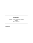
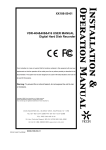
User's Manual
Digital Hard Disk Recorder
Table of Contents
1. Warning / Safety Instruction .............................................................................................................................. 1
1.1. Warning ...................................................................................................................................... ................. 1
1.2. Safety Instructions ....................................................................................................................................... 2
2. Specification ....................................................................................................................................................... 2
3. Accessories ......................................................................................................................................................... 4
4. Front Key Functions ...................................................................................................... ..................................... 4
5. Rear Panel Functions ...................................................................................................................... .................... 6
6. Basic Operation .................................................................................................................................................. 7
6.1. Power ON/OFF ........................................................................................................................................... 7
6.2. Recording..................................................................................................................................................... 8
6.3. Playback....................................................................................................................................................... 8
6.4. Search........................................................................................................................................................... 8
6.5. Back up......................................................................................................................................................... 9
6.6. Software Upgrade ........................................................................................................................................ 9
6.7. Client Program............................................................................................................................................. 9
7. Basic ID / Password ......................................................................................................................................... 10
1. Warning / Safety Instruction
1.1. Warning
Warning
Please follow instruction to prevent any kind of damage or loss. If you do not follow this instruction,
it might bring severe damage or loss.
The symbol is intended to alert the user to the presence of important operating and maintenance (servicing)
instructions in the literature accompanying the unit.
The symbol is intended to alert the user to the presence of uninsulated "dangerous voltage" within the product's
enclosure that may be of sufficient magnitude to constitute a risk of electric shock to persons.
Warning
This equipment has been tested and found to comply with the limits for a Class A digital device,
pursuant to part 15 of the FCC Rules. These limits are designed to provide reasonable protection
against harmful interference when the equipment is operated in a commercial environment. This
equipment generates, uses, and can radiate radio frequency energy and, if not installed and used in accordance
with the instruction manual, may cause harmful interference to radio communications. Operation of this
equipment in a residential area is likely to cause harmful interference in which case the user will be required to
correct the interference at its own expense.
1
Caution
Any changes or modifications in construction of this device which are not expressly approved by the party
responsible for compliance could void the user's authority to operate the equipment.
Caution
Danger of explosion, if battery is incorrectly replaced. Replace only with the same or equivalent type.
Warranty will be made void if the product is disassembled or manipulated by the user.
1.2. Safety Instructions
1. Read these instructions.
2. Keep these instructions.
3. Heed all warnings.
4. Follow all instructions.
5. Do not use this apparatus near water.
6. Clean only with dry cloth.
7. Do not block any ventilation openings. Install in accordance with the manufacturer‟s instructions.
8. Do not install near any heat sources such as radiators, heat registers, stoves, or other apparatus (including
amplifiers) that produce heat.
9. Do not defeat the safety purpose of the polarized or grounding type plug. A polarized plug has two blades
with one wider than the other. A grounding type plug has two blades and a third grounding prong. The wide
blade or the third prong is provided for your safety. If the provided plug does not fit into your outlet, consult an
electrician for replacement of the obsolete outlet.
10.Protect the power cord from being walked on or pinched particularly at plugs, convenience receptacles, and
the point where they exit from the apparatus.
11.Only use attachments/accessories specified by the manufacturer.
12.Use only with the cart, stand, tripod, bracket, or table specified by the manufacturer, or sold with the
apparatus.
When a cart is used, use caution when moving the cart/apparatus combination to avoid injury from tip-over.
13.Unplug this apparatus during lightning storms or when unused for long periods of time.
14.Refer all servicing to qualified service personnel. Servicing is required when the apparatus has been damaged
in any way, such as power-supply cord or plug is damaged, liquid has been spilled or objects have fallen into the
apparatus, the apparatus has been exposed to rain or moisture, does not operate normally, or has been dropped.
15.The apparatus shall not be exposed to dripping or splashing and that no objects filled with liquids, such as
vases, shall be placed on the apparatus.
16.The mains plug is used as the disconnect device. The disconnect device shall remain readily operable.
2. Specification
Model
Image System
Multi-tasking
Video Channel
8ch DVR
16ch DVR
NTSC, PAL, AUTO selectable
Quadplex
16CH Composite, 16CH Loop through,
8CH Composite, 8CH Loop through, BNC
BNC
2
Video Output
Video
Compression
Display Resolution
Recording
Resolution
Recording Quality
Max Display
Speed
Max Recording
Speed
Max Playback
Speed
Time Laps
Recording Interval
(fps)
Recording Mode
Playback Search
Playback Speed
Slow Motion
Sensor Input
Alarm Output
(Relay)
Audio In/Out
Network
3G
Private Function
Motion Detection
Hard Disk
ESATA PORT
Hard Status
Backup
PTZ Control
Serial Port
System Log
Language
S/W Upgrade
Password Function
Power Source
Dimension
Operating
Temperature
Weight
HD, VGA, CVBS 1EA, SPOT 3EA
H.264
1280x1024(50hz,60hz),1440x900(60hz),1920x1080p(50hz,60hz),1920x1080i(NTSC) /
1280x1024(50hz,60hz),1440x900(60hz),1920x1080p(50hz,60hz),1920x1080i(PAL)
720x480, 720x240, 360x240 (NTSC) / 720x576, 720x288, 360x288 (PAL)
4 Levels (Low, Normal, High, Highest)
240 fps (NTSC)
480 fps (NTSC)
200 fps (PAL )
400 fps (PAL )
240 fps (NTSC)
480 fps (NTSC)
200 fps (PAL )
400 fps (PAL )
240 fps (NTSC)
480 fps (NTSC)
200 fps (PAL )
400 fps (PAL )
1,2,3,4,5,6,7.5,10,15,30 (NTSC, 10 Steps)
1,2,3,4,5,7.5,12.5,25 (PAL, 9 Steps)
Schedule, Event (Alarm, Motion, Video loss Detection), Manual
Calendar, Event (Alarm, Motion, Video loss Detection)
x1, x2, x4, x8, x16 (Forward, Backward)
x1/2, x1/4, x1/8,
8 (NO/NC Selectable)
16 (NO/NC Selectable)
4 (NO/NC) Relay
4 (NO/NC) Relay
In: 8ch , Out: 1ch
In:16ch , Out: 1ch
10/100/1000 Base-T (Static, DHCP, E-mail), DDNS
iPhone, iPad, android
22x18 (NTSC) / 22X18(PAL)
22x18 (NTSC) / 22x18 (PAL), 5 Level Sensitivity
3EA
1EA
SMART Function ( Hard status )
USB(Ver2.0), CD-RW/DVD-RW, Network
RS-485
RS-232(Console, Reserved)
TBD
TBD
Network, USB Memory Stick
Power OFF, MENU, Record OFF, Key Lock
Free Voltage (100 – 240VAC, 50Hz/60Hz, 60W)
350(W) X 400(D) X 88(H)
5℃ ~ 40℃
6Kg (without HDD)
• Above specification features of the product are subject to change without prior notice.
3
3. Accessories
• DVR
• Power Cable
• AUDIO IN/OUT CONNECTOR 1EA.
• DVR assembly and other screws
• User's Manual
• Remote Controller (Option)
• Software CD ( RAMS PRO, Uniplayer PRO, FULL_Manual )
4. Front Key Functions
4.1 DVD-RW
- This enables you to back up with ease.
4.2 Button for Recording Playback
- RECORD : This key button initiates the forced recording except the continuous recording mode. Pressing this
key button makes all live video channels start recording and pressing it one more time stops the recording.
- R.PLAY (Reversed Play) : This is to initiate the reversed playback during forward playback. On PTZ control
mode, this key button is to be used to lower the controlling speed.
- PAUSE : This key button freezes the playback mode until it's pressed again
- PLAY : This is a playback start button and it initiates the playback of pre-selected channel, starting file, and/
or audio when it's pressed during live mode. On live mode PAUSE status, this button resumes the playback.
In case of PTZ controlling mode, it can be used to increase the controlling speed. On still image viewing
menu, it is also being used for image back up.
- EXIT : This key button allows you to stop the playback while playing.
- MENU : MENU comes up for any functions on any channels on play back/ live mode.
4.3 LED Display
- POWER : Green light is on the system is on stand-by mode
- REC : Red light flickers on recording mode.
4
- NET : Green light flickers when the Network is connected.
4.4 Function button
- LOCK : This is to prevent any unwanted system manipulation by unauthorized personnel. Pressing this key
one time, DVR turns into locking status. Afterward any key touch will call up the password input dialog box.
Key lock will be released only when you input the correct password.
- FRZ(Freeze) : This is to pause the display screen on live mode. Pressing this key button one more time lets
you go back to previous mode.
- PTZ(Pan/Tilt/Zoom) : This key button allows you to enter Pan/Tilt/Zoom/Focus mode. Pressing this key
button one more time lets you go back to previous live display mode.
- ZOOM : This is to be used to zoom in, or zoom out the specific display area on live mode.
- SEARCH : This is to search the video data files that are recorded on HDD.
- MULTI : The user can utilize this key to set split channels from 1 to 8 / 1 to 16. When the key is pressed, It
shows 1, 4, 9, 13 and 16 split channel display in sequential order. And it happens on both live and playback
modes.
- SEQ(SEQUENCE): This is to see all channels in sequential order where the video input data is detected on
live mode. CAMERA_SEQUENCE setting value decides channels to be split and shown.
Split screen(1/ 4/ 9/ 13) mode let the screen split in sequential order. By pressing SEQ button one time, it is
converted to PAGE SEQUENCE. Pressing it again, CAM SEQUENCE.
4.5 Numeric button : This button is to be used for inputting network IP address, password (on dialog box
display) and channel selection on live mode or playback mode.
4.6 Direction selection button
- UP : On menu status, this key button can be used to select the detailed item by moving the cursor upward.
On PTZ controlling status, this key button can be used to move the camera upward. On playback mode, this key
allows you to switch the channel.
- DOWN : On menu status, this key button can be used to select the detailed item by moving the cursor
downward. On PTZ controlling status, this key button can be used to move the camera downward. On playback
mode, this key allows you to switch the channel.
- LEFT : On menu status, this key button can be used to change the setting value. On PTZ controlling status,
this key button can be used to move the camera left direction. On playback mode, this key allows you to lower
the playback speed.
.-RIGHT : On menu status, this key button can be used to change the setting value. On PTZ controlling status,
this key button can be used to move the camera right direction. On playback mode, this key allows you to
increase the playback speed.
.-OK : On menu status, this key is used to confirm and execute the selected function.
4.7 IR Reception : This is to accept the IR data from the remote controller.
4.8 Jog/ Shuttle
- Jog : This is to see the image recorded carefully in the forward/ reverse direction.
- Shuttle : The user can run speedy playback by using jog shuttle in the forward/ reverse direction.
4.9 Front USB port : This USB port is to be used to back up the video data, or captured still image from HDD.
Also this USB port supports USB mouse controlling for easy DVR operation with front input location advantage.
5. Rear Panel Functions
5
5.1 POWER INPUT
- This port is for powering on. (Free Voltage, 100 ~ 240VAC, 50hz/ 60hz)
5.2 POWER SWITCH
- This is the switch for POWER ON/OFF.
5.3 Video Output
- MAIN: This port is for VIDEO OUT and supports CVBS VIDEO OUT and 1EA is provided.
- SPOT: This port is for SPOT VIDEO OUT and supports CVBS VIDEO OUT and 3EA is provided
5.4 Video Input
- IN: This port is for VIDEO INPUT and supports CVBS VIDEO input
- OUT: This port is for LOOP OUT of VIDEO INPUT. It can be used for VIDEO INPUT on other DVRs and
channels.
5.5. Alarm Output
- 4EA is provided. When an event takes place, contact output runs at certain time set and continues for some
time set from setting values. There are 2 ways of contact output which are NO and NC.
* NO(normal OPEN) : When alarm is activated, NO port is connected to COM port while disconnected in
normal condition.
* NC(normal CLOSED) : When alarm is activated, NC port is disconnected to COM port while connected in
normal condition.
5.6 Audio In/out
- 1 of each INPUT(16CH : 1~16, 8CH : 1~8) and OUTPUT is supported through EXTENSION PORT.
5.7 Alarm Input
- ALARM IN can be connected to 16 sensors(8 sensors for CH8) of 2 ways such as NO/NC. And it also can set
the connecting system with mode choice and input channel on menu.
6
5.8 HD
- It enables high resolution output of main image to be done through HD port.( Maximum 1920 * 1080P)
5.9 VGA
- This port exports the same video output signal under VGA signal standard. (DSUB-15 Connector)
5.10 RS-232
- RS-232 SERIAL TYPE : This enables you to control the external controller through RS-232 SERIAL
5.11 RS-485
- RS-485 SERIAL TYPE : This enables you to control the external controller through RS-485 SERIAL. And it
also enables you to control PTZ.
5.12 E-SATA
- E-SATA connector is supported for EXTERNAL HDD extension.
5.13 ETHERNET
- (10/100/1000 Mbps) RJ-45 connector
6. Basic Operation
6.1. Power ON/OFF
6.1.1 Power ON
- When power cable is connected and power switch on the back panel of the DVR is on, the power LED light
turns to red showing the DVR is on stand-by mode and ready for power on. The capacity of the HDD might
change the boot time. The boot time depends on the capacity of the HDD.
While booting, a bar moves showing its progress. When DVR booting process is completed, OSD (On Screen
Display) menu is displayed on screen. At the same time, you can hear the buzzer sound, alerting that DVR
booting process is completed. Now the user can manipulate the DVR at his convenience.
6.1.2 Power OFF
- When powering off the DVR system, please press „SHUT DOWN‟ on system set up menu..
Then you will see the password input dialog box pop up for your password input (Default : 111111) to turn off
the DVR system. After entering your password, the message about the completed shutting down the system will
be shown and switch off the power switch on the back panel of the DVR.
6.1.3. Date Time Setup
This is to input the date time of DVR system. After changing the date time of DVR, you must press OK key
button on date time menu to activate the date time application.
6.1.4 Password
This is to change the user‟s ID and password for the DVR system.
6.1.5 Network Setup
Select the appropriate network type from the network setup menu. Select the network type among STATIC,
DHCP, DDNS
6.2. Recording
7
6.2.1 Recording Menu Setup
Details are to be selected from Recording Setup menu. Firstly select the resolution. Selectable resolutions are 3
different choices. i.e. (NTSC) : 720x480(D1), 720x240(Half D1), 360x240(CIF) and (PAL) : 720x576(D1),
720x288(Half D1), 360x288(CIF) . Then audio recording selection and recording quality per channel is to be set.
Recording qualities are 4 optional choices i.e. NORMAL, LOW, HIGH, HIGHEST. In this category, the user
can make the choice per individual channel or per all channel at his own convenience. And finally recording
condition is selectable. See “Full manual 3.2 Recording set up menu” for the details.
6.2.2Recording Condition Setup
You can set values for REC1, REC2, REC3. See “Full manual 3.2 Recording set up menu” for the details.
6.3 Playback
6.3.1 Direct Playback by using PLAY button
When pressing PLAY button, DVR starts the playback according to the playback setting condition of selected
channel, playback starting point and audio playback option.
6.3.2 Audio Playback
In case of running the recorded video data file with audio link included, select the channel with the mouse and
click „RIGHT” button and then the menu for audio appears. And select „AUDIO ON” and click „PLAY BACK”.
Then audio plays back automatically. When using the key on the front panel, press „OK” button and select the
channel and press „OK” button again then then the menu for audio appears. After this, the steps for play back is
same as above
6.4 Search
DVR provides 4 types of Search Modes.
6.4.1 Search Mod
Quick Search : Enter YYYY/MM/DD.
Calendar Search : For easy search of recorded data, DVR provides the calendar search format.
Event Search : This shows the recorded data list generated by ALARM, MOTION, VIDEO LOSS
Overlapped List : This shows the overlapped data caused by changing the time.
6.4.2 Search Method
Quick Search : Press “SEARCH” button and then the 4 search modes come up.. Select “TIME” out of the 4
modes and enter YYYY/MM/DD and time. Press “OK” button and the recorded data on all channels for the
selected time play back at once.
Calendar Search : By pressing Search button, 4 different Search modes come up. Out of these 4 modes,
please select Calendar search menu. Calendar search selection calls up the Year, Month, Day window. Once
you select the Year, Month Day, then the hour minute window comes up. Once you select the hour minute, all
channels on this time frame will start playing back.
Event Search : By pressing Search button, 4 different Search modes come up. Select event menu and set event
search condition to ON/OFF and select LOG list and then the list of the events occurred appears. Then select
and play them.
Overlapped List : By pressing Search button, 4 different Search modes come up. Select “Overlapped List” out
of the 4 modes and the list of the overlapped data caused by changing the time appears. Then select and play
them.
6.5 Back up
6.5.1 DVD-RW
8
- By installing DVD-RW DRIVER, you can back up the video recorded for a certain period of time from HDD
into CD-ROM/DVD-ROM.
- Select DVD/RW as a TARGET and select backup time, file, channel and click WRITE and then DVR starts to
back up.(Selecting „ESTIMATE‟ leads to calculating the capacity of the backup file.)
6.5.2 USB Memory Stick
By connecting USB memory stick into USB port, you can back up the data manually. The user can back up
the video data from HDD to USB device by using System setup > Backup menu.
• After connecting USB memory stick into USB port, select „USB‟ as a target and go through this step ; select
backup time, file, channel and click WRITE and then DVR starts to back up.(Selecting „ESTIMATE‟ leads to
calculating the capacity of the backup file)
• By keeping SimplePlayer program in USB memory stick where the backup video data is located, the user
can execute the playback at any time.
Uniplayer Pro is included in the CD/DVD and you can play them with other PCs with ease.
6.5.3 Network
• By using network from remote site, the user can transfer the video and audio data from DVR HDD to user's
PC for back up.
6.6 Software Upgrade
1) Copy the F/W file into USB memory stick and insert it into the USB port on the front of the DVR.
2) Reboot the DVR and then the menu screen comes up as image A-1
3) Click OK button to upgrade, Click CANCEL button to cancel.
4) When upgrading, the process rate is shown as image A-2
image A-1
image A-2
5) When message for upgrade completed is shown, remove the USB memory stick and Click OK button.
6) After rebooting, upgrading completes.
6.7 Client Program
6.7.1 RAMS PRO
- This program enables you to monitor the live image and search and play the data on the DVR by connecting
the DVR through network remotely. Clients can back up the data with this program.
- S/W can be upgraded with this program.
- Active RAMS PRO and click the button and then the management page for the DVR lists. Create a group in
connect and enter NAME, ADDRESS, PORT , ID, PASSWORD of the DVR. And click ADD button to save.
- Default value is as follow : PORT - 7000, ID - ADMIN, PASSWORD - 111111
9
6.7.2 Uniplayer PRO
- This program enables you to play back the data recorded on RAMS PRO and captured. Backup data can be
played back as well.
6.7.3 Mobile viewer
- This program enables you to monitor live video and the status of DVR by using mobile devices
like PDA or Smart Phone that support wireless internet connection.
- i-RAMS PRO : This program enables you to monitor live video and the status of DVR by using i-Phone.
- a-RAMS PRO : This program enables you to monitor live video and the status of DVR by using Android
phone.
7. Basic ID / Password
- You can register the users up as the following provided accounts for the DVR : ADMIN1, ADMIN2, USER1 ~
USER6.
- You can register the users up as the following provided accounts for the CLIENT : ADMIN1, ADMIN2,
USER1 ~ USER6.
- For the first time setup, only ADMIN account has the following default password. The other users' accounts
are
to be activated only when you set up each user's password in advance.
• ID : ADMIN
• Password : 111111
10