1
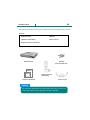
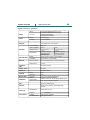
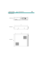
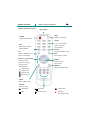
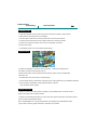
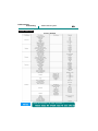
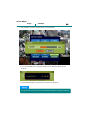
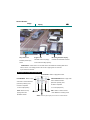
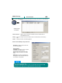
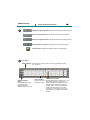
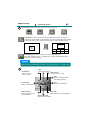
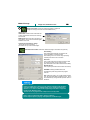
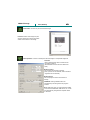
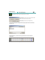
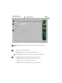
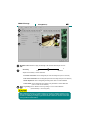
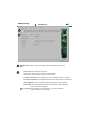
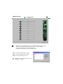
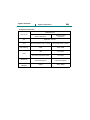
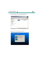
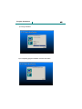
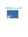
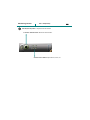
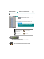
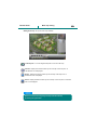
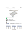
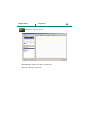
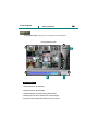
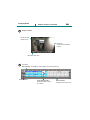
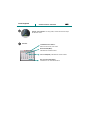
DIGITAL VIDEO RECORDER OPERATION MANUAL (Rev. 2-1) Safety precautions 2 Failure to follow these instructions could result in serious personal injury or death. Failure to follow these instructions could result in personal injury or property damage. Notifies user of references to use conveniently. Install this equipment avoiding a direct ray of light, heats and moistures. -Doing not, can result in lowering efficiency, electric shock or fire. Do not pull electric wire or do not touch power plug with wet hands. -Can result in electric shock or fire. Do not bend the power cable forcedly or do not press it with heavy materials. -Can result in electric shock or fire. Do not use damaged power cord or loose outlet plug. -Can result in electric shock or fire. Do not use the outlet fully. -Can result in electronic shock or fire. Do not disassemble, repair or convert this product without permission. -Can result in electric shock or fire. When repair is required, contact the service center. Do not open the cover of the product at your convenience or do not insert inductive stick into the ventilation hole. -Especially, SMPS is open, so only professional technicians are allowed to work on. Do not place equipment on the inclined or uneven plane. -Can cause lowering of efficiency or malfunction. Do not vibrate or shock in operation. -Can cause out of order with equipment and hard disk (HDD). 3 Content check Open the box at the clean and even place. And read user manual thoroughly before you install. Contents •DVR main frame •HDD Key •Software CD and Manual •Power code set •Remote Controller (with battery) DVR mainframe HDD Key (Only with HDD rack) Manual S/W CD Software CD / Manual Remote Controller (with Battery) Power cord set Check the items supplied with your DVR system. Refer to the pic above and contact your dealer if you find anything is missing or damaged. Contents Preparation 4 Safety precautions-------------------------------------------------------------------------------------------2 Contents check-----------------------------------------------------------------------------------------------3 I. System overview System characteristics------------------------------------------------------------------------------------7 System specification----------------------------------------------------------------------------------8,9,10 System appearance----------------------------------------------------------------------------------------11 System connection---------------------------------------------------------------------------------12,13,14 Front description--------------------------------------------------------------------------------------------15 Remote controller description--------------------------------------------------------------------------16 II. DVR Installation and start DVR installation---------------------------------------------------------------------------------------------18 Default value of system-----------------------------------------------------------------------------------19 III. How to use Monitoring screen Monitoring screen------------------------------------------------------------------------------------------21 Status bar------------------------------------------------------------------------------------------------------22 Layout----------------------------------------------------------------------------------------------------------23 Operation of the others-----------------------------------------------------------------------------------24 IV. How to use SETUP SETUP menu-------------------------------------------------------------------------------------------------26 Camera---------------------------------------------------------------------------------------------------------27 Virtual keyboard---------------------------------------------------------------------------------------------28 Motion----------------------------------------------------------------------------------------------------------29 Motion area select------------------------------------------------------------------------------------------30 Sensor----------------------------------------------------------------------------------------------------------31 Record----------------------------------------------------------------------------------------------------------32 Schedule-------------------------------------------------------------------------------------------------------33 System ----------------------------------------------------------------------- 34,35,36,37,38,39,40,41,42 Backup-------------------------------------------------------------------------------------------------43,44,45 Backup playback--------------------------------------------------------------------------------------------46 V. How to use Search SEARCH screen-----------------------------------------------------------------------------------------48,49 Play--------------------------------------------------------------------------------------------------------------50 VI. How to use REMOTE Environment condition / Function restriction------------------------------------------------------52 Connection/Connection menu--------------------------------------------------------------------------53 Remote button------------------------------------------------------------------------------------------------54 Remote search-----------------------------------------------------------------------------------------------55 Image adjust / Timetable----------------------------------------------------------------------------------56 Layout / Play button----------------------------------------------------------------------------------------57 Image / AVI saving------------------------------------------------------------------------------------------58 Print / Back up------------------------------------------------------------------------------------------------59 Open & Backup playback---------------------------------------------------------------------------------60 Remote Setup(Camera)------------------------------------------------------------------------------------61 Remote Setup(Motion)---------------------------------------------------------------------------------62,63 Remote Setup(Sensor)-------------------------------------------------------------------------------------64 Remote Setup(Record)------------------------------------------------------------------------------------65 Remote Setup(System)-------------------------------------------------------66,67,68,69,70,71,72,73 Contents 5 VII. How to use VIEWER Introduction & Environment condition---------------------------------------------------------------75 Open & Backup playback---------------------------------------------------------------------------------76 VIII. How to use CENTER System characteristic-------------------------------------------------------------------------------------78 System composition/supplements--------------------------------------------------------------------79 Program installation---------------------------------------------------------------------------80,81,82,83 Use certification---------------------------------------------------------------------------------------------84 Graphic interface-------------------------------------------------------------------------------------------85 Split screen---------------------------------------------------------------------------------------------------86 Center menu/Volume button----------------------------------------------------------------------------87 Pantilt(preset)------------------------------------------------------------------------------------------------88 Mini map-------------------------------------------------------------------------------------------------------89 DVR list/Local playback/Finish-------------------------------------------------------------------------90 DVR management-------------------------------------------------------------------------------------------91 E-MAP management---------------------------------------------------------------------------------------92 Main map setting--------------------------------------------------------------------------------------------93 Sub map setting-----------------------------------------------------------------------------------------94,95 Others setting------------------------------------------------------------------------------------------------96 Log search----------------------------------------------------------------------------------------------------97 Step to playback--------------------------------------------------------------------------------------------98 Graphic interface/Time table----------------------------------------------------------------------------99 Layout button/Playback button-----------------------------------------------------------------------100 Image backup/ Print--------------------------------------------------------------------------------------101 Volume control/Calendar-------------------------------------------------------------------------------102 IX. How to use Dynamic IP IX. Appendix Overview------------------------------------------------------------------------------------------------------104 Sequence to use DDNS ---------------------------------------------------------------------------------105 Registration DDNS account and HOSTNAME------------------106,107,108,109,110,111,112 DVR Network setup----------------------------------------------------------------------------------113,114 Router port forwarding-----------------------------------------------------------------------------115,116 Hardware SPEC & Reference--------------------------------------------------------------------------118 Tip for IE & Hard disk-------------------------------------------------------------------------------------119 FAQ [frequently asked question]---------------------------------------------------------------------120 Product Warranty------------------------------------------------------------------------------------------121 6 l. System overview System overview System characteristics 7 System characteristics ■ The best level of system stability -Stable operating environment based on embedded LINUX -H/W safety devices such as power reset function in power failure, Watch-Dog function, etc. -S/W safety device such as buzzer alarming in image loss, image system recovery function, etc. ■ High definition monitoring, recording and high speed recording -Maximization of security effectiveness with high definition monitoring screen of 720*480 -Records up to 120 frames ( referenced at 320*240 ) -High definition recording is available with maximum 720*480 ( PAL:720*576 ) size ■ Convenient and various recording schedule -Increased user convenience with supporting of pallet type of recording schedule -Supports a variety of schedules such as regular, motion, sensor, manual, etc. -Can be understood weekly schedule with color coded distinction ■ Various motion detection functions ( Motion Detection ) -Convenient area selection with 330 detailed cells ( referenced at NTSC ) and user friendly tools -Function to control alarm in motion detection -Function to specify recording before / after detecting motion ■ Network support function ( Remote monitoring / Search / Backup ) -Remote monitoring with up to 10Mbps speed -Can search in remote site the backed up image in DVR -Backup is available for the transmitted real time images to remote site and remote searching image -Saving by AVI from searched moving images in remote site (Play in Windows Media Player.) ■ Pan / Tilt ( PTZ ) control function -4 direction diversion function and zoom, focus adjustment function -Supports various protocols including PELCO, VICON, etc. ■ 4 Channel Audio recording function -Maximize efficiency of surveillance by saving images and sound at once with 4ch Audio. -ADPCM audio recording ■ Convenient search function -Support timetable type search which can distinguish recording schedule, recording per timeline and else, at a look. -Beginners also can use conveniently in the step of date->time->minute ■ Built-in RS485 Converter -As default, built in RS485 converter, you do not have to buy converter for PTZ control. System overview 8 System specification System specification - 4CH Model INPUT VIDEO AUDIO INPUT 4 Composite BNC(NTSC/PAL)-1Vp-p 1 Composite BNC(NTSC/PAL)-1Vp-p 1 S-VHS, VGA Option 4 Composite Loop-Back 4 Line-In(RCA) OUTPUT 1 Line-Out(RCA) OUTPUT DISPLAY RECORD 720x480(NTSC), 720x576(PAL) COMPRESSION VIDEO FORMAT MPEG-4 NTSC PAL RESOLUTION 720x480, 720x240 360x240 720x576, 720x288 360x288 120FPS/4CH(360x240) 100FPS/4CH(360x288) MUX MODE REC. METHOD MOTION 60FPS/4CH(720x240) 50FPS/4CH(720x288) 30FPS/4CH(720x480) 25FPS/4CH(720x576) MODE Always, Manual, Motion, Sensor, S+M CONTROL By Resolution, FPS & Quality MOTION AREA 4CH 22x15(NTSC,PAL:22x18) Areas Setup SENSITIVITY 8 Level CONTROL UNIT IR Remote Control SERIAL PORT RS-232C PAN/TILT RS-485 Supports MULTI TASK INPUT OUTPUT TRIPLEX 4CH 4CH Playback, Record and Network TCP/IP FUNCTIONS 10Base-T Ethernet, DHCP,DDNS,WEB Support NETWORK SENSOR Live, Search, Backup, Upgrade HDD 40,80,120,160GB Upper BACKUP USB1.1(1EA), Network, Removable HDD CD-RW PHYSICAL ELECTRICAL DEMENSION 38(W)x42(L)x7.3(H) WEIGHT POWER CONSUMPTION 12Kg(With HDD) 100~240 VAC, 50/60Hz 50W(approximately) System overview 9 System specification System specification - 8CH Model INPUT VIDEO AUDIO INPUT 8 Composite BNC(NTSC/PAL)-1Vp-p 1 Composite BNC(NTSC/PAL)-1Vp-p 1 S-VHS, VGA Option 8 Composite Loop-Back 4 Line-In(RCA) OUTPUT 1 Line-Out(RCA) OUTPUT DISPLAY RECORD 720x480(NTSC), 720x576(PAL) COMPRESSION VIDEO FORMAT MPEG-4 NTSC PAL RESOLUTION 720x480, 720x240 360x240 720x576, 720x288 360x288 120FPS/8CH(360x240) 100FPS/8CH(360x288) MUX MODE REC. METHOD MOTION 60FPS/8CH(720x240) 50FPS/8CH(720x288) 30FPS/8CH(720x480) 25FPS/8CH(720x576) MODE Always, Manual, Motion, Sensor, S+M CONTROL By Resolution, FPS & Quality MOTION AREA 8CH 22x15(NTSC,PAL:22x18) Areas Setup SENSITIVITY 8 Level CONTROL UNIT IR Remote Control SERIAL PORT RS-232C PAN/TILT RS-485 Supports MULTI TASK INPUT OUTPUT TRIPLEX 8CH 4CH Playback, Record and Network TCP/IP FUNCTIONS 10Base-T Ethernet, DHCP,DDNS,WEB Support NETWORK SENSOR Live, Search, Backup, Upgrade HDD 40,80,120,160GB Upper BACKUP USB1.1(1EA), Network, Removable HDD CD-RW PHYSICAL ELECTRICAL DEMENSION 38(W)x42(L)x7.3(H) WEIGHT POWER CONSUMPTION 12Kg(With HDD) 100~240 VAC, 50/60Hz 50W(approximately) System overview 10 System specification System specification - 16CH Model INPUT VIDEO AUDIO INPUT 16 Composite BNC(NTSC/PAL)-1Vp-p 1 Composite BNC(NTSC/PAL)-1Vp-p 1 S-VHS, VGA Option 16 Composite Loop-Back 4 Line-In(RCA) OUTPUT 1 Line-Out(RCA) OUTPUT DISPLAY RECORD 720x480(NTSC), 720x576(PAL) COMPRESSION VIDEO FORMAT MPEG-4 NTSC PAL RESOLUTION 720x480, 720x240 360x240 720x576, 720x288 360x288 120FPS/16CH(360x240) 100FPS/16CH(360x288) MUX MODE REC. METHOD MOTION 60FPS/16CH(720x240) 50FPS/16CH(720x288) 30FPS/16CH(720x480) 25FPS/16CH(720x576) MODE Always, Manual, Motion, Sensor, S+M CONTROL By Resolution, FPS & Quality MOTION AREA 16CH 22x15(NTSC,PAL:22x18) Areas Setup SENSITIVITY 8 Level CONTROL UNIT IR Remote Control SERIAL PORT RS-232C PAN/TILT RS-485 Supports MULTI TASK INPUT OUTPUT TRIPLEX 16CH 4CH Playback, Record and Network TCP/IP FUNCTIONS 10Base-T Ethernet, DHCP,DDNS,WEB Support NETWORK SENSOR Live, Search, Backup, Upgrade HDD 40,80,120,160GB Upper BACKUP USB1.1(1EA), Network, Removable HDD CD-RW PHYSICAL ELECTRICAL DEMENSION 38(W)x42(L)x7.3(H) WEIGHT POWER CONSUMPTION 12Kg(With HDD) 100~240 VAC, 50/60Hz 50W(approximately) System overview System appearance <Front view> <Side view> <Top view> System appearance 11 System overview 12 System connection System connection – 4CH Model Camera input 1~4 Ch Monitor output Power input LOOP OUT 1~4 Ch (100V~240V switch) NTSC/PAL switch Audio input 1~4Ch Sensor / Alarm / 485(PTZ)connection Speaker output VGA output (option) Network connection (10Mbps) S-VIDEO output ¾You should be careful about polarity of (+),(-) when connect Pan/Tilt device. ¾If wiring is wrong, the DVR may not be operated or malfunction. ¾Although maximum communication distance of RS-485 is about 1.2Km, it may be changed according to cable type or status. ¾For a lamp and the devices powered by AC, should be used separate external relay. System overview 13 System connection System connection – 8CH Model Camera input 1~8Ch Monitor input Power input LOOP OUT 1~8Ch (100V~240V switch) NTSC/PAL switch Audio input 1~4Ch Sensor / Alarm / 485(PTZ)connection Speaker output VGA output Network connection (10Mbps) S-VIDEO output ¾You should be careful about polarity of (+),(-) when connect Pan/Tilt device. ¾If wiring is wrong, the DVR may not be operated or malfunction. ¾Although maximum communication distance of RS-485 is about 1.2Km, it may be changed according to cable type or status. ¾For a lamp and the devices powered by AC, should be used separate external relay. System overview 14 System connection System connection – 16CH Model Camera input 1~16Ch Monitor output Power input LOOP OUT 1~16Ch (100V~240V switch) NTSC/PAL switch Audio input 1~4Ch Sensor / Alarm / 485(PTZ)connection Speaker output VGA output Network connection (10Mbps) S-VIDEO output ¾You should be careful about polarity of (+),(-) when connect Pan/Tilt device. ¾If wiring is wrong, the DVR may not be operated or malfunction. ¾Although maximum communication distance of RS-485 is about 1.2Km, it may be changed according to cable type or status. ¾For a lamp and the devices powered by AC, should be used separate external relay. System overview 15 Front description Front description REMOVABLE HDD RACK Remote controller IR sensor or CD-RW POWER button NUMBER button ( 1~0 ) MENU button 4 direction / Display change ENTER / PTZ LCD Description REPALY button USB port LCD JOG / SHUTTLE JOG / SHUTTLE Description 1.Power OFF Fast rewind REW( Stand by! 2.During system operating (No record) REW X 1 Fast forward ) FF( PLAY ) FF X 1 2005/11/08 RUN REW X 2 5SEC TOGGLE FF X 2 - STEP + 11 : 34 : 55 RUN REW X 3 FF X 3 3. Record 2005/11/08 REC / 5SEC TOGGLE 11 : 34 : 55 REC \ SHUTTLE : As you turn, the speed of display increases JOG : As you turn left and right, displays image move step by step on display. System overview Remote controller description 16 Remote controller description light-emitting MUTE POWER Audio output ON/OFF System power ON/OFF Number *1~0 :1 screen display OSD *Date / Time setup Monitoring / Playback *write password Graphic ON/OFF Rotation PTZ Change the screen in order PAN/TILT adjustment menu EXIT (Only on 1Ch display) Exit from setup & menu Direction / Layout change ENTER *Move in the menu Select or confirm (up, down, left, right) setup & menu *Layout change / SEARCH PTZ adjustment Move to the search menu 1 layout screen 4 layout screen 9 layout screen 16 layout screen SETUP Move to SETUP menu DISPLAY Button for replay Fast Rewind Play/Pause Fast Forward Stop Forward by step Recording (On manual record) 17 II. DVR Installation and Starting DVR installing and starting DVR installation 18 Installation order 1.Open the packages and then make sure that all contents are included, to take out DVR. 2.Mount DVR on the location where it is installed. 3.Connect camera cable to the camera input terminal on the rear panel of DVR. 4.Connect monitor cable to the monitor output terminal on the rear panel of DVR. 5.Connect such cables as network, PTZ, audio, etc. depending on purpose. 6.Plug in power cable. 7.Automatically power is on and the system starts booting. System starting Initializing… 8.Images are displayed on the screen and a paragraph, “initializing” is displayed over the images, to make booting process going on. 9.When system starts, such procedures are processed as system check and initialization, HDD check, etc. 10.It takes about 40 to 50 seconds for system booting. 11.Once system booting is terminated, monitoring screen mode (quad screen) is immediately displayed. 12.For recording and operating, change required settings in SETUP. (refer to SETUP window usage) System termination 13.When you want to terminate system if necessary, press POWER button on remote control or system front panel under monitoring window. 14.System is immediately terminated if you select YES when system termination confirmation window pops up and then press ENTER button. But, if PASSWORD is set, only after authentication is completed when PASSWORD window pops up after confirming system termination, termination is completed. DVR installing and starting Default value of system 19 System default value Default Account Value: ID: admin Password: 1 Please change the default value for more safe usage.!! 20 III. How to use Monitoring screen Monitoring screen usage 21 Monitoring window 1 2 <16CH> <4CH> 1 <8CH> Monitoring screen window: Window that is displayed first when system boots, where you can monitor LIVE video. Mode displayed on monitoring window 1.Channel indication (camera name) Changeable in SETUP>CAMERA 2.Status/Time indication window ON/OFF with OSD button of remote control 3.SOUND ON/OFF indication ON/OFF with MUTE button of remote control 4.Pan/tilt (PTZ) adjustment GUI 5.1 screen Ù 16(4, 9) split screen Adjustment window opens from PTZ button on remote control Click 0-9 number button Ù Click Direction button 6.Screen Rotation Click Right Rotation button( ) of remote control Monitoring screen usage 2 STATUS BAR 1 1 2 3 22 Status bar 2 3 4 In Back-up status , Activated with blue icon blinking display When network is connected, Activated with green icon blinking display HDD usage in percentage. In RECYCLE mode, If hard disk is full, recording is proceeded continuously by deleting the first recorded data, so the capacity of hard disk always maintains 99% level. 4 Current time When you change the time display form, you can change it in SETUP>SYSTEM>DISPLAY Display form : YYYY/MM/DD -> MM/DD/YYYY -> DD/MM/YYYY Monitoring screen usage 23 Screen layout How to split the screen Click the direction button on the remote control or on the front of the system. <1 layout screen> <16 layout screen> <4 layout screen> *4/8ch model : Not use <8 layout screen> *4ch model : Not use Direct channel If you want to watch the specific channel, press the channel No. on the remote control Or front panel. Ex) Watch the channel No.1 : Press No. 1 Using the NO.1 button cause you a little time delay due to the same number use of No.10~16. Monitoring screen usage 24 Others 4 3 1 2 1 Sound ON/OFF Sound output is changed ON/OFF with MUTE BUTTON. 2 Layout convert (ROTATION) With ROTATION button ( 3 ) can convert into the other layout. Status Screen Graphic (OSD) ON/OFF With OSD button ( ) can change ON/OFF, status bar, title of camera, REC, etc that displayed on the screen. 4 How to use PAN / TILT (PTZ) 1.Connect PTZ device to 485/422 terminal on the rear panel of system. 2. Select the protocol of the corresponding PTZ device in SETUP>SYSTEM>PTZ. 3.Match PTZ ADRESS in SETUP>CAMERA. 4. Under monitoring mode choice screen to adjust PTZ by one layout. 5.Open the PTZ control menu, pressing PTZ button on remote controller/front panel. 6.After selecting the Item among the PAN/TILT, ZOOM, FOCUS, press ENTER. 7.Control with direction key. 8.When exiting, press EXIT key. [PTZ CONTROL window pop-up] 25 IV. How to use SETUP SETUP MENU 26 usage SETUP MENU 1 2 3 5 6 4 SETUP MENU: SETUP MENU window is displayed if SETUP button of front panel or remote control is pressed, where you can change the settings for the detailed functions of the respective items. Characteristics per menu CAMERA : Menu to change the setting values for each camera image such as color adjustment, name change, etc. MOTION : Menu to change setting values such as motion area setting, alarm link control in motion detection, etc. SENSOR : Menu to change setting values such as sensor type, alarm link control in sensor detection, etc. RECORD : Menu to change setting values such as recording definition, recording type, recording frame, etc. SYSTEM : Menu to change PASSWORD, OSD, HDD management, other setting values BACKUP : Menu to do backup of the recorded data When PASSWORD is set, PASSWORD window is displayed prior to SETUP MENU, and only after PASSWORD input is correct, you can proceed with SETUP MENU. SETUP MENU usage 1 CAMERA 27 CAMERA: Mainly used to change the setting value in respect to camera window. Description of function per item 1. CAMERA NUMBER : selects CAMERA. 2. BRIGHTNESS : adjusts the brightness of camera images( 1 ~ 100.) 3. CONTRAST : adjusts the contrast of camera images( 1 ~ 100.) 4. HUE : adjusts the hue value of camera images( 1 ~ 100.) 5. SATURATION : adjusts the color saturation of camera images( 1 ~ 100.) 6. TITLE : used to give names of the respective channels( refer to virtual keyboard usage.) 7. VIDEO LOSS ALARM : used to make buzzer sound if there is no image signals. 8. P/T/Z ADDRESS : used to allocate PAN/TILT CAMERA address. SETUP MENU usage Virtual keyboard 28 VIRTUAL KEYBOARD: Used substituting for keyboard when you change camera name. Usage 1.Press ENTER after moving to BACK SPACE button ( ) using UP/Down/Left/Right buttons. 2.Delete the existing camera name written in INSERT window by pressing Arrow button continuously. 3. Press ENTER button after positioning to the letter you want by using UP/Down/Left/Right buttons. 4.Repeat until the paragraph you want is completed. 5.Press EXIT button for confirmation window to popup. 6.Select YES to save and exit. SETUP MENU usage 2 MOTION 29 MOTION: Mainly used when you change the setting values related with camera screen. Description of function per item 1. CAMERA NUMBER : select CAMERA. 2. MOTION AREA : used to select MOTION area( refer to motion area setting method.) 3. SENSITIVITY : select MOTION sensitivity ( 1 ~ 8. ) 4. PRE-EVENT RECORD TIME : item to specify recording how many seconds before detecting motion( DISABLE, 1 to 5 seconds.) 5. POST-EVENT RECORD TIME : item to specify recording how many seconds after detecting motion( DISABLE, 1 to 60 seconds.) 6. LINKED ARARM : item to select alarm that is to be linked when the corresponding camera detects motion. 7. ALARM OUTPUT TIME : item to select how many seconds the alarm goes off. 8. LOG WRITING : Whether to log-write or not SETUP MENU usage MOTION area assignment 30 MOTION area assignment: Mode to specify the area depending on each cell detecting the motion Usage [In selecting area] 1. Select MOVE to move the detection where you want. (default) 2. Press ENTER key to popup area specification tool window. 3. After select SELECT, press ENTER and then select the area by moving direction button. [In deleting area] 1. Press ENTER key to pop up area specification tool window. 2. Press ENTER after selecting ERASE, then you can delete the area by moving direction button. SELECT ALL: Select entire area of screen as detection area. ERASE ALL: Delete all area that has been specified as detection area. SETUP MENU usage 3 SENSOR 31 SENSOR: Used when you set which operation is taken under sensor detection. Description of function per item 1. SENSOR NUMBER : select SENSOR. 2. SENSOR TYPE : use to select sensor type( NORMAL OPEN / NORMAL CLOSE.) 3. LINKED CAMERA : item to set up which camera will be linked to record when SENSOR detects( only when the linked camera is set to SENSOR in RECORD MODE, sensor recording is available.) 4. PRE-EVENT RECORD TIME : item to specify how many seconds to record before sensor detection (DISABLE, 1 to 5 seconds.) 5. POST-EVENT RECORD TIME : item to specify how many seconds to record after sensor detection (DISABLE, 1 to 60 seconds.) 6. LINKED ALARM : item to select the alarm to be linked when corresponding camera detects sense. 7. ALARM OUTPUT TIME : item to select how many seconds alarm goes off. 8. LOG WRITING : Whether to log-write or not SETUP MENU usage 4 RECORD RECORD: Mainly used to set up how the recording is made. Description of function per item 1. CAMERA NUMBER : select CAMERA. 2. FRAME RATE : select how many frames is recorded per second. The number of frames is set up depending on selection of SYSTEM RESOLUTION. ( )=PAL -. 720 * 480(576) : 30(25)FRAMES -. 720 * 240(288) : 60(50)FRAMES -. 640 * 240(288) : 120(100)FRAMES 3. QUALITY : select recording definition. -. LOWEST, LOW, NORMAL, HIGH, HIGEST 4. RECORD MODE : used to select RECORD MODE. -. OFF, ALWAYS, MOTION, SENSOR, MANUAL, MOTION + SENSOR 5. SCHEDULE : operated when RECORD MODE is on SCHEDULE. 6. AUDIO : select when you save AUDIO per channel. 32 SETUP MENU usage SCHEDULE 33 SCHEDULE Used in setting schedule. It can be set by hour based on 24-hour system. Setting mode: ALWAYS, MOTION, SENSOR, M + S, MANUAL, OFF Usage 1. While SCHEDULE window is displayed, press ENTER button for TOOL selection window to popup. 2. After selecting the recording mode you want, press ENTER to go to SCHEDULE window. 3. Fill the colors using Up/Down/Left/Right buttons. 4. When you want to change recording mode, press ENTER button again. 5. After selecting again the recording mode you want, press ENTER to go to SCHEDULE window. 6. Fill other colors moving with using Up/Down/Left/Right buttons. 7. When SCHEDULE is completed, press EXIT button and then select YES in confirming window. SETUP MENU usage 5 34 SYSTEM SYSTEM: Set up the system related items. Usage 1 ACCOUNT: Controls account administration and shows account types below. ADMIN: Account to edit all set-up and use of functions of the system. USER: Uses all functions of the system except system set-up. NETWOTK: Connected through Remote program, no system set-up. Set password for system security after purchasing it, and be careful not to forget the PASSWORD SETUP MENU usage 35 SYSTEM Input user name. Input password. Input password again. Select account type. 2 TIME SET: Change the time of the system. If you change the date and time to the past ones, the recording data of system is deleted that much, so you should be careful. 3 LOAD CONFIGURATION Invoke the system set-up value. When FROM is USB DEVICE, this shows the saved value In Load Configuration DEFAULT, USB has the data value, DEFAULT executes FACTORY DEFAULT. =>SYSTEM REBOOT!! 4 SAVE CONFIGURATION Save the system set-up value in USB memory. Set up the title of the set-up value SETUP MENU usage 36 SYSTEM RESOLUTION: Change the Recording Resolution. 5 Set up the resolution. When not in AUTO, set up the maximum CAPTURE value per each channel. Means GROUP1. Means GROUP2. <Maximum recording Image size is increasing as the resolution is frames per resolution> higher, and the available dates of recording z 720 * 480(576) : 30FRAMES are reduced compared to HDD capacity, so z 720 * 240(576) : 60FRAMES select appropriate resolution matching the z 360 * 240(288) : 120FRAMES security level. AUTO set-up means that the system sets the frames per each channel Automatically, but if not AUTO set-up, the total frames of CAPTURE should be 30(25) for 720x480(576), 60(50) for 720x240(288). In case of 360x240(288), the subtotal frames of Group1 or Group2 are 60 per each, So the total frames are 120. SETUP MENU usage 6 37 SYSTEM DISPLAY: Item to set display menu Displays the camera title or not. Selects the status bar type. Adjusts screen changeover time. Changes the time display form. 7 OSD (On Screen Display): Adjust the graphic window that is displayed on the screen. Adjusts the graphic transparency. Adjusts the X location value. Adjusts the Y location value. 8 DISK CONFIGURATION: Set up the HDD for recording. Using only built-in HDD : BUILT-IN Using removable HDD : REMOVABLE Using built-in HDD + removable HDD: BUILT-IN+REMOVABLE SETUP MENU usage 9 38 SYSTEM DISK FORMAT: Item to format HDD specified for recording. Use in case of formatting HDD For the items such as DISK CONFIGURATION, DISK FORMAT, all the data recorded are deleted when the settings are changed, so you must be very careful! 10 RECORDING POLICY: Selecting the recording mode : one time / recycle ONE TIME : one time recording RECYCLE : recycle recording 11 DISK CAPACITY: Show the HDD capacity and usage (This is just show the information) For the partition composition and each data organizing to operate system It is supposed to different from the HDD label. SETUP MENU usage 39 SYSTEM 12 NETWORK: Item to set network environment for remote access. Specify IP setting mode. STATIC: select to use static IP. DHCP: select to use dynamic IP allocation mode. Select maximum connection. (Available 1~4) Specify service port address Specify NAME SERVER Specify GATEWAY Specify NETMASK This DVR system has its own Web Module inside, so Live monitoring and PTZ control through windows’ Internet Explorer is available. Specify IP address 13 DDNS: Item to select DDNS server that support Dynamic DNS, available to choice between EZDDNS.COM (own DVR server) and Public server DYNDNS.ORG. Specify DDNS SERVER name. Specify the registered HOSTNAME. Specify the registered USERNAME. Specify the registered PASSWORD. Check whether NETWORK of DVR is Connected with IP sharing Router. (If use the ADSL modem, don’t check it.) Refer to an Dynamic IP usage SETUP MENU usage 40 SYSTEM 14 P/T/Z: Item to set in operating of PAN/TILT camera or receiver. Select the corresponding model with Left/Right key on Remote control/Front panel. 15 HOLIDAY: Item to specify holiday. On the registered holiday, it is operated according to the recording mode of Sunday of the schedule of each camera. How to operating HOLIDAY mode z Select date in the same month : Click Enter after moving with using Up/Down/Left/Wight key z Switch to other month : Click Up/Down key of first line and last line of calendar z Move to list window : Click Right key on the most right line of calendar z Move to OK, CANCEL button : Click Left key on the most left of calendar Click Right key on List window z Delete of selected date : Select the date to delete and click ENTER button SETUP MENU usage SYSTEM 41 16 EVENT LOG: Item to log a variety of status information of system. 17 FIRMWARE UPGRADE: Item to upgrade SOFTWARE for system operation. How to upgrade with USB device (USB MEMORY STICK / USB HDD) 1.Make the ‘down’ folder on the Root directory of PC and then copy the new S/W on that folder. Firmware file : firm_fs……dvr 2.Open SETUP>SYSTEM>FIRMWARE UPGRADE in system main frame. 3.Run the UPGRADE automatically. How to upgrade connecting NETWORK 1.Set Network, specifying IP address on the system main frame. 2.Open SETUP>SYSTEM>FIRMWARE UPGRADE on the screen. 3.Excute Firmup program in PC. 4.Send new program file in Firmup program. 5.New program is sent to corresponding system. SETUP MENU usage SYSTEM 42 18 DVR INFORMATION: Shows the current system version. When it comes to the popup window with OK or Cancel button in the setup category, You should click OK, then the setup value is applied to the system. Ex) System, Backup… But regarding the other rest setup values in the setup category, You just exit from the setup category to monitoring screen, then the setup value is applied to the system. SETUP MENU usage 6 BACKUP 43 BACKUP Use it when you want to do backup the recorded data. REMOVABLE HDD, USB storage media, CD-RW, etc. can be used as backup device. How to do backup into the removable HDD 1. Select SETUP>BACKUP. 2. Select time line to do backup. (FROM: starting date/time, TO: ending date/time) 3. Select backup device.( the devices not installed are invisible.) 4. Execute FORMAT. (When using less than 32G HDD, you may format it with FAT32) 5. When FORMAT is completed, select BACKUP to start backup. USB memory device that is only formatted on DVR is not recognized in WINDOWS based PC, but is recognized only on DVR. If you like to read in WINDOWS, do format in PC. BACKUP speed gets a little slower when you select random, not all cameras. SETUP MENU usage BACKUP 44 5. After FORMAT completed, select BACKUP and start BACKUP. 6. If you press ENTER button, preparation progress bar for BACKUP appears like the pic above. 7. If actual BACKUP begins, progress status is shown as the pic above. Can get back to monitoring screen during BACKUP progress (background backup) SETUP MENU usage BACKUP 45 HOW TO DO BACKUP WITH CD-RW 1. Select SETUP>BACKUP item. 2. Select time range to do backup (FROM: beginning date/hour, TO: ending date/hour.) 3. Select backup device CD-RW (uninstalled device is not shown.) 4. Insert CD-R media into CD-RW. 5. Press BACKUP button to start backup. (CD-R does not need to be formatted. However, CD-RW media needs to be formatted in advance in PC to be used.) 6. When you press ENTER button, BACKUP preparation progress bar appears and backup begins like the pic above. 7. If actual BACKUP begins, progress can be shown as follows. In CD-RW backup, be careful that connected network is terminated by force for system stability. In case of CD backup, you don't need additional software to view in your PC Mini Viewer is implemented. SETUP MENU usage BACKUP PLAYBACK PROCEDURE ON BACKUP PLAYBACK USAGE 1. To playback backup data, go into search screen by pressing SEARCH button. 2. Select device BACKUP, and then press OK button. 3. Backup search window is activated (without backup data is NO BACKUP DATA.) 4. Select backup data to be played back at BACKUP LIST window. 5. When you press ENTER, backup data’s info appears. 6. Select wanted hour and minute range, and then press ENTER to play back. 7. In order to play back recorded data again, get out of search screen mode and get into search screen mode again. 46 47 V. How to Search Search Screen usage SEARCH SCREEN 48 ENTER ENTER HOW TO OPERATE SEARCH 1. Press SEARCH button to activate search screen. 2. Select wanted data among recorded dates on calendar, and press ENTER button to move to timetable. Search Screen usage SEARCH Screen 49 3.Move to the hour you want using the direction key in hour table. (If you input directly the hour using number button or using jog shuttle on front panel of DVR, you can move more faster.) 4. Move to the minute you want using the direction key in minute table.. (If you input directly the hour using number button or using jog shuttle on front panel of DVR, you can move more faster.) 5.Pressing ENTER in minute table will play the images of the corresponding channel right now. Left/Right button in hour/minute table is used to move over timeline, and Up/Down button is used to select the channel. Search Screen usage 50 Replay Play status icon: Progress bar: Recording date/time display: Indicates present play Indicates where it is playing Indicates recorded date and time. status. of the entire recording capacity. SEARCHING…:When there is no recorded area in the middle of recording data due to motion, sensor, or recording pause in the course of playing this icon is shown if you search the area fast. Description of remote control operating PLAY/PAUSE : Button to play/pause video. FASTREWIND : Button to play FASTFORWARD:Button to play video video fast in reverse direction. Fast in forward direction. (whenever pressing once, (whenever pressing once, increase is repeated increase is repeated in one to triple speed.) in one to triple speed.) STOP : Button to stop REC : Button to start to record playing and exit to under MANUAL recording mode. SEARCH window. STEP : Button to play images per one scene in forward direction. 51 VI. How to use REMOTE REMOTE Usage Environment conditions/restriction function 52 2 3 1 4 <REMOTE PROGRAM IS?> With remote connection to DVR, it is a remote program to perform remote monitoring, remote search, remote backup etc. Environment conditions for REMOTE program 1. INTEL P-3 or higher PC(P-4 recommended) 2. 64M or higher main memory(128M or higher) 3. WIN98 or higher O/S(WIN XP,2000 recommended) 4. VGA card that supports YUV(ATI kind) 5. 1Mbps or higher network speed at least (supports 10Mbps at largest) For common use later in function upgrade & channel expansion, some of buttons and graphics may not be activated at this moment. Please understand. REMOTE usage 1 Connection/Exit 53 Access button: Clicking this button will popup Connection List window to make REMOTE access. <DVR Connection List window> New Connection… :Button to enter such items as address and user authentication to make REMOTE access. Modify… :Button to modify such items as address and user authentication of the existing lists. Delete… :Clicking this button will delete logged list. <New Connection/Modify dialogue window> DVR Name : Specify random name that you can easily identify. Display Method YUV mode: According to your PC graphic card ability, the support can be decided,This mode shows faster, clear ability of image transmission than RGB mode. RGB mode: It is widely compatible with most graphic cards, and select this when YUV mode is not supported. Recommended graphic card ATI series : XPERT2000 / Radeon series or higher (More than minimum 16M) RIVATNT series : M64 series or higher (More than minimum 16M) REMOTE usage Remote button 54 IP Address: Specify IP address that is allocated to the DVR to connect. What is IP address? A set of address system that is used to find out destination in network access via Internet or LAN. IP address is divided into REAL IP and VIRTUAL IP, and REAL IP must be set on DVR for the access from remote site via Internet. You can be assigned with REAL IP or DDNS service ID (Hostname of Dynamic Domain Name Server). Service Port: Set this the same to the service port assigned to DVR. What is service port? Function to make the virtual IP available to the devices such PC or DVR with automatic connection to the specified service port when remote access is made to router via the router or IP Share of one REAL IP. (But, this function is available only when router or IP Share supports it.) Communication speed: Select transmit speed. User Name: Type the user name certified in DVR. Password: Type the password certified in DVR. 2 3 4 Remote Live backup button: Saving the images shown by transmission right now to PC Remote Search button: search or saving to remote the information recorded in DVR or open and search the information in the back up (refer to 54p~59p) Remote Set button: Button to set various things for DVR use. (Clicking this button will switch from monitoring screen to setting screen.) (refer to 60p~72p) After Remote setup, when you press OK, the DVR system shuts down and reboots to make the setup value be applied to the system. You can reconnect to the system after the reboot processing time of 40~50 seconds. REMOTE usage 55 Remote Search 5 4 1 6 2 3 1 Search screen Camera number Camera name Green border line :displays the selected camera. Time/Date of recording REMOTE usage 2 Image adjustment/Timetable 56 Brightness adjustment button:adjusts the brightness of playing images. Contrast adjustment button: adjusts the contrast of playing images. Sharpness adjustment button: adjusts the sharpness of playing images. Blurring adjustment button: adjusts the blurring of playing images. Initialize button:initializes the adjusted image to original image. 3 Time Table Timeline Display: It is displayed in 24 hour system, and one line selected is made of 1 minute unit. Camera Selection button: Plays images after going to the layout of the location where the selected camera is shown. Time Selection Pointer: Time Scroll Bar: Hand shaped pointer to select the time you Scroll bar to move to want, which functions to select time timeline you want. right and left while up and down to select a camera of the cameras shown in the left side. That is, switching is available to another camera location in the course of searching in one display, by clicking this pointer on the corresponding camera location. REMOTE usage 4 57 Layout/Play button Layout button: Button to select the split mode of the image to play. 1*1 display 2*2 display 4*4 display 3*3 display Frame Search: Function to show the image to play frame by frame, so when you momentarily miss the image you are searching, you can stop searching and then select the previous frame promptly, to load it on main window. (used in precision search) MAIN WINDOW MAIN WINDOW 1st 2nd 3rd 4th 5th 6th 7th 8th Partial Magnify: Function to magnify a part of the image searched. (Click Partial Magnify button in 1*1 display mode, and then click left mouse button on the part you want to magnify) Frame Search and Partial Magnify functions are selectable only in 1*1 display mode. 5 Fast Rewind :Fast reverse play every 1 minute Stop :Aborts image playing Fast Forward :Fast play every 1 minute Exit :Exits to monitoring screen after ending searching Play :Play in forward direction Reverse Play :Play in reverse direction Previous Frame :Play of previous frame in reverse direction Next Frame :Play of next fame in forward direction Speed control bar :Speed control in playing REMOTE usage 6 Image save, Animation save 58 Image Save button: saves the searched images in image file. (image format supports JPG format and BMP format.) Image Format JPG format: Definition has a little loss due to loss compression method, but archiving size is small. BMP format: Archiving size is big due to no compression, but it can be saved as higher definition than JPG. Inserting of information in image :Check this to insert recording information on top of the saved image. Animation Save button: Saves the searched image in animation file (AVI file). Save Setting Auto Setting:Automatically converted to the frame specified in recording setting. User Setting: User can convert it by specifying randomly the frame to be converted Save Info Item to select the start time and end time as well As camera number for the image to save. (End time/date must be later than Start time/date.) Backup Device Item to specify the device and location for backup. CDR/DVD: Clicking Initialize button will format/backup with using Direct CD program of Roxio. ETC: Select this when you use all storage medias such as Removable HDD, USB device, etc., which Are automatically recognized as separate drives in Windows. What is AVI file? Refers to format type in which you can view the animation with automatic execution of Browser such as Media Player if you double click the file in Window, i.e., it refers to Audio/Video supporting format that is supported by Microsoft Windows series. The file size is very big because compression is hardly made. How to view recording time/date in playing of AVI fileCheck Caption option in playing backup AVI file via Media Player. REMOTE usage Print, Backup 59 Print button: Function to print the searched image. Preview:Preview of the images to print, which is printed with various information written on the bottom of the image. Backup button: Function to backup the searched image to compressed image file. Save Info Item to select the start time and end time for the image to backup. (End time/date must be later than Start time/ date.) Backup camera Item to select the camera for backup. (One or plurals can be selected, and all cameras supported can be selected.) Backup device Item to specify the device and location for backup. CDR/DVD: Clicking Initialize button will format/backup with using Direct CD program of Roxio. ETC: Select this when you use all storage medias such as Removable HDD, USB device, etc., which are automatically recognized as separate drives in Windows. REMOTE usage Open (backup play) 60 Open button: Function to play the image backup by recalling it. Regular Replay: used to play the image recorded in DVR. (Default mode selected in Search Screen) Backup Replay: used to play the image backup. Checking Backup Play and clicking OK button will popup Open window to find backup index file (*.idx). Selecting backup file, *.idx file and clicking Open button will list the backup data in Time Table. REMOTE usage Setup(Camera) 1 2 3 1 Select All:Checkbox to apply the settings of all cameras identically at one time. 2 Title: Item to revise the camera name. P/T/Z Address: Item to assign PAN TILT address per camera. Video Loss Alarm: Function to inform Video Loss by beep sound per camera. 3 Brightness:adjusts the brightness of the image to record and live. Contrast: adjusts the contrast of the image to record and live. Hue: adjusts the Hue of the image to record and live. Saturation: adjusts the sharpness of the image to record and live. 61 REMOTE usage 62 Setup(Motion) 1 2 3 1 2 4 Select All:Checkbox to apply the settings of all cameras identically at one time. Sensitivity 5 Dull Sensitive Adjusts the sensitivity in motion detection. Pre-event record time: Item to designate pre-event recording time (max. 5 seconds.) Post-event record time: Item to designate post-event recording time (max. 60 seconds.) Alarm output time: Item to designate generating-alarm time on motion detected. Linked alarm: Item to designate which alarm to be generated on motion detected. (One or more can be selected.) 3 Log writing: Item to decide to save Log writing or not on motion detected. (Saved at Setup -> Event log item) Motion detection function is a mode to detect in accordance with the amount of color changes of image, be careful that it is checked as continuous motion when the image of camera is blinking according to light due to failure of Auto Iris function or that sort of things without actual motion. REMOTE usage 4 63 Setup(Motion) Area: Item to designate motion detection area. When you put the mouse on the screen displaying images and drag, area is marked. <Tool for area designation> Square area designation Area designation button Area deletion button Line area designation Dot area designation Select All: To be used to select or delete the whole area on the screen. REMOTE usage Setup(Sensor) 64 1 2 1 2 Select All:Checkbox to apply the settings of all sensors identically at one time. Sensor type: Part to designate sensor type. Normal Close: Sensor type that is closed in normal situation. Normal Open: Sensor type that is open in normal situation. Pre-event record time: Item to designate pre-event recording time (max. 5 seconds.) Post-event record time: Item to designate post-event recording time (max. 60 seconds.) Alarm output time: Item to designate generating-alarm time on sensor detected. Linked alarm: Item to designate which alarm to be generated on sensor detected. (One or more can be selected.) Log writing: Item to decide to save Log writing or not on sensor detected. (Saved at Setup -> Event log item) REMOTE usage Setup(Record) 65 1 2 1 Select All:Checkbox to apply the settings of all cameras identically at one time. 2 Quality: Item to control recorded image quality. (Lowest / Low / Normal / High / Highest, Total 5 levels are available to control.) Lowest Low Normal High Highest Frame rate: Item to control recording frames. Record mode: Item to select recording mode. Off / Always / Motion / Sensor / Motion+Sensor / Schedule / Manual mode are available. Audio: Item to select which audio channel to be used among 4 audio input totally. REMOTE usage Setup(System) 1 2 3 4 5 6 7 8 9 1 Account: Item to assign/edit/delete user’s certified accounts. There are 3 levels. Admin level: Administrator’s level to do all of monitoring/searching/setup. User level: User’s level to do monitoring/searching. Network level: Network level to do only network access. Add: To be used to generate new accounts. Edit: To be used to edit accounts’ contents. Delete: To be used to delete accounts. Enable: Item to designate whether to certify For SETUP on Enable. 66 REMOTE usage 2 Setup(System) 67 Resolution: Item to designate recording resolution. 360*240 / 640*240 / 640*480 (NTSC base) – three kinds. Maximum assigned frames are decided at each resolution. 360*240(360*288): 120fps(100fps) 720*240(720*288): 60fps(50fps) 720*480(720*576): 30fps(25fps) Auto: In case of Auto checked, it calculates average frames per channel to distribute. (In case of concentrating or decreasing frames on specific channels, do not check Auto and distribute frames at your convenience.) It is possible to operate the system only when the total frames per resolution of Group 1 and Group 2 are accurate, and if the frames are not accurate, they will not be reflected to the system. REMOTE usage 3 Setup(System) Display: Item to change the items related to system display. Camera title: Item to check to show camera title or not. Status bar: Item to select to show the status bar by graphic (GUI) or text style. Rotation time: Item to designate rotating time when you try to rotate each split screen by pressing Rotation button. Date format: Item to adjust time format according to each country’s style. 1) YYYY/MM/DD 2) MM/DD/YYYY 3) DD/MM/YYYY Totally 3 types 68 REMOTE usage 4 Setup(System) 69 OSD: Item to revise OSD (On Screen Display) things. Transparency: Control the transparency for all graphic screens. It's the most dark when it's 0% and it's most tranparent when it's 70%. Origin X: Control to right and left of the Graphic screens.( Controllable within -15~0~15) Orgin Y: Control to up and down of the Graphic screens.( Controllable within -15~0~15) 5 Recording Policy: Item to designate recording type. One time and Recycle. One Time: To cease recording on 100% of HDD capacity. Recycle: When HDD capacity is almost consumed, it erases old data and record new data. So this style maintains certain capacity all the time. REMOTE usage 6 Setup(System) 70 Network: Item to set network circumstances for remote access. IP Setting: Item to select one among Disable / Static / DHCP. 1) Disable: Does not use Network. 2) Static: Uses Network with static IP. 3) DHCP: Automatic IP assigning type that uses IP assigned from DHCP server with using Dynamic Host Configuration Protocol. (It is convenient when you use this inside LAN circumstances.) Max connection: Designates maximum number of access to the DVR system through network. Service port: Item to designate required Service port on Port Forwarding to make it possible to get access to terminal’s virtual IP under the circumstances that are using Router or Cable/DSL Router. (DVR’s default port is assigned to 9013.) IP: Item to input IP address. Netmask: Item to leave Host computer’s address after filtering network part of IP address. Gateway: Point to do role for entrance or link to other servers. Name server: Address equivalent server to do role of guide to domain. The contents above need to be consulted by network supervisor and you need to get the accurate information. REMOTE usage 7 Setup(System) 71 DDNS: Service to make it possible to get access with registered ID and host name at DDNS instead of IP address when you try to connect DVR with using dynamic IP. It stands for Dynamic Domain Name Server. Server: Item to select EZDDNS of DVR supplier and DYNDNS which is public server. Hostname: Item to log host names registered at DDNS server. Username: Item to log users’ ID registered at DDNS server. Password: Item to log password assigned on DDNS server registration. Please refer to DDNS Usage at Supplement. REMOTE usage 8 Setup(System) 72 P/T/Z: Item to match the protocols of Speed Domes or Receivers for PAN/TILT/ZOOM. Protocol: Item to select the protocol of Receivers or Speed Domes to be used. Please contact DVR supplier when you do not have the protocols of the equipment to be used. REMOTE usage 9 Setup(System) 73 Holiday: Item to designate holidays. It follows Sunday mode on the designated dates. Choose the date -> Click Add button -> Register Holiday Sunday mode works as scheduled on Schedule, so you need to schedule Sunday without failure on Holiday usage. 74 VII. How to use VIEWER VIEWER usage Introduction 75 1 <VIEWER program?> Available to see it on the PC, the backup data from Removable HDD, CD-RW, USB-Memory Stick etc. of the DVR. As the DVR is based on the Linux, using Ext3 format, it needs the Viewer program to see the backup data on the normal Windows, after back it up on the HDD formatted as the Fat32. PC condition for using the VIEWER program 1. Higher than INTEL P-3 PC(P-4 recommend) 2. Higher than 64M memory(128M recommend) 3. O/S higher than WIN98(WIN XP,2000 recommend) 4. VGA card supporting YUV(ATI recommend) For upgrading or extending the channel later, some common button & graphic might not be supported. Please understand it. VIEWER usage 1 76 Operating & Backup playback Operating & Backup playback As the window to find the backup data, “ *.idx” on the backup data location as the below; Backup playback screen Layout button -Select one screen or quad splitting screen Exit button Playback button Playback Speed Control bar Image storage button (JPG or BMP) Print button Open button AVI storage button (Moving picture) Normal Backup button (Image and Index) Time table Calendar -Easy to know the recorded time -Recorded date of backup data -Record mode by the color Refer to the REMOTE usage, regarding each button and menu. 77 VIII. How to use CENTER System Overview Character SYSTEM CHARACTER ■ Remote monitoring without limit of connections -max 36ch simultaneous monitoring -No limit of local connection - Audio support in the 1ch - Main & sub screen support (switch from image to e-map) ■ Remote control - Remote control is available of PTZ camera in the remote ■ Remote search - Remote search is available in the remote ■ Speedy transmission & easy management - Speedy transmission (max. 100Fps:self test) - Management of each camera by section - Status check of DVR or camera - Auto connection by the local DVR status ■ Log info of center status or each DVR status - Log recording center operating status. - Log recording operating status and selected info of each DVR ■ E-map to overview each DVR - 2 step manage by One main map and nine sub map - Icon by DVR, camera, sensor, alarm status - Sub screen change into image directly by clicking - Icon location & direction setting is available per map ■ Local pop up to inform the DVR of the emergency - Pop up support per DVR - Pop up support to inform emergency of the DVR not monitored ■ Speed up available according to the system specification - Speed up is available according to the system specification 78 System Overview 79 System composition ■ System composition COMPOSITION CATEGORY Recommended composition Basic composition OS WIN2000 , WIN XP CPU More PENTIUM-4 CEL 1.0GHz More PENTIUM-4 1.6GHz Main Memory 128M More 256M 16M More 32M ATI series / RIVATNT series ATI series MONITOR 15” (1024*768 support) More 17” (1024*768 support) NETWORK (SPEED) 1Mbps More 3Mbps VGA Program Installation 1) Execute the Setup. exe file in the Center program folder 2) Progress to set up by clicking the “Next” button 80 Program Installation 3) “I Agree” -> “Next” button 4) Select the location to set up (recommend default value) 81 Program Installation 5) is being installated 6) For completing program installation click the “OK” button 82 Program Installation 7) Execute the Center program 83 Monitoring Screen User Certification 84 User Certification You should register user certification to execute the program Speed up function : - Use all speed up function - Use basic speed up function - Non use speed up function Speed up function is? To display image more softly and fast H/W of the Graphic card is operated. Overlay board or YUV format etc is used in the DVR center program. It supports the better and faster image quality but, after check this function, if the image is not displayed normally please reset it. Default value is User name : admin Password : 1 Please change the default value for more safe usage.!! Monitoring Screen 85 Graphic Interface 1 6 7 8 4 2 5 9 3 1 Graphic Interface Camera No. Camera Name DVR Name Green Layout :Show selected camera. DVR-0 P Using Device P: Using Pan/Tilt A: Using Audio In the More than16 split screen(36 split) the Camera name and DVR name is showed in shortly due to the screen size. Monitoring Screen 2 86 Split Screen Split Screen Button :Show the screen according to the selected split 1ch 4ch 9ch 16ch 36ch Image scroll You can page up and down using the scroll bar in the right of screen. Monitoring Screen 3 Center Menu / Volume button Center Menu : Main Button for DVR managing, E-MAP managing, User register and Log setting, Log search etc. DVR MANAGING : Manage the DVR list and detail data to connect E-MAP : Manage the E-MAP. User register and Log setting : Mange the User or Center program. Set up the option of log info Search Log : Show the recorded log info 4 Volume button : When the audio is used adjust the volume. 87 Monitoring Screen 5 Pan / Tilt (Preset) Pan/Tilt (Preset) button : Adjust the Pan/Tilt camera. 4 direction Pan/Tilt button :Move the each direction. zoom/focus/iris button: Adjust Zoom, Focus, Iris. 88 Monitoring Screen 6 89 Mini Map Mini map : It shows camera, sensor, alarm of main map. Camera status : : normal (blue) : motion detection (red) : Video Loss (gray) Alarm status : : normal (blue) : alarm operating (red) Sensor status : : normal (blue) : sensor detection (red) Image / map change It can be changed the mini map and image by double click. double click! double click! Open sub map Close sub map You can show the sub map by clicking the sub map icon in the main map and show the main map by clicking the closing icon in the sub map. Monitoring Screen 7 DVR list / local playback / finish 90 DVR list : It shows each DVR, camera list and current status. DVR list : It shows DVR status and name. Camera list increase / shorten : Increase/shorten the camera list in the DVR. Camera list : It shows the camera status and name. *Select the ON/OFF by clicking the camera icon. *Change into one channel image by clicking the camera name. DVR status icon :No connection (gray) :Connect (yellow) Camera status icon :Non use (gray) :Use (yellow) 8 Local playback : Recording data in the selected DVR is played ( Refer to the Remote playback section) 9 Finish : Finish the center program and exit to the window. Center menu DVR management 91 DVR management : Manage the DVR list. Connection : Connect the listed all DVRs. Disconnection : reset the all connections. DVR add / correct DVR name : DVR name to connect IP address : IP address to connect Service port : Service port of the DVR to connect User authorization : account of DVR to connect DVR connection list registration :Register in the DVR connection list. Center menu E-MAP management 92 E-map management : Manage the sub map on the screen. Open : Open the image file to use for main map. (Support JPG, BMP file, It is optimized in 780 x 590 (fixel)) Delete : Delete the icon on the map. Close : Close the setting dialog on the main map. Reset the alarm : Release all activating alarm on the map. Sub map : Manage the sub map. (be able to manage 9 sub map. If the sub map is not on the map you can add new sub map.) Center menu Main map setting Setting main map : Set up the main map condition. Sub map icon : You can drag and drop this icon on the main map. Camera : Display the camera location (In the sub map “main map icon” is checked this icon is displayed. Sensor : Display the sensor location (In the sub map “main map icon” is checked this icon is displayed. Alarm : Display the alarm location (In the sub map “main map icon” is checked this icon is displayed. Each icon can be moved by drag and drop and edit sub map by clicking the right button 93 Center menu 94 Sub map setting Setting sub map : Set up the sub map condition. Arrange the sensor, camera and alarm etc on the map. Open : Open the map to use for sub map. (Support JPG, BMP file, It is optimized in 780 x 590 (fixel) ) Delete : Delete the icon on the map. Close : Close the setting dialog on the sub map. TEXT : DVR number, channel is displayed under the map. Camera/Sensor/Alarm : Set up the camera/sensor/alarm on the map. <camera setting> <sensor setting> <alarm setting> Center menu Sub map setting Map title : Set up the current sub map. ICON : Set up the icon on for the main map. Each icon can be moved by drag and drop and change the character by clicking the right button. Icon character Del : Delete icon Main map icon : Select if you want to display it. Up, down, left, right : Select the camera direction. 95 Center menu Others setting Others setting : Setting the user account or log recording. Add / correct of the user : Set up the center S/W user. Log setting : Select events to record as the log info among the various events. Start / Finish : Record user & time on the center program starting and finishing. 96 Center menu Log search Log search : Search the log data Renew the data : Update the log data to the latest data. Delete all : Delete all recorded data. 97 Local Playback 98 Step to playback Local playback button : Display the recorded data in the selected DVR <Local playback screen> 4 3 1 3 5 6 7 2 2 Step to playback 1. Select the date (in the calendar) 2. Select the time (in the time table) 3. Playback (Display recorded image by PLAY button) 4. Showing the one screen (Double click selected image) 5. Frame search (Click the frame search in the one screen) 1 Local Playback 1 Graphic interface / Time table 99 Graphic interface Camera number Camera name Green line :It indicates the selected camera. Recording date / time 2 Time table Time indicator: it is divided by minute (fine line) and time (thick line). Camera select Time setting pointer: Setting the camera & time you want to Time scroll bar: Setting the time by this bar. Local Playback 3 100 Layout button / display button Layout button : Select the split mode. 1*1 2*2 3*3 4*4 Frame search : It shows the image frame by frame. (Use to search closely) Main Main first second fifth sixth third fourth seventh eighth Partial Zoom : Enlarge the image partially (Push this button and click the left button of the mouse in the 1*1 screen) 4 Playback button Stop :Stop the playback. Fast Rewind : It rewind by minute. Fast Forward : It forward by minute. Exit :Finish the search Reverse Play : Play Next Frame :Play the next frame Previous Frame :Play the previous frame Speed control bar Audio play only in ×1 speed. Local Playback 5 Image back up / Print Image backup : back up the image (JPG or BMP) Image format JPG :Size is small but image value might be lost. BMP : Better image that JPG format but size is large. Put in image data :Check if you want to put in the recording image data. Print button : prints out the searched image. Preview: shows the printing image. It indicates the detail info of the camera. 101 Local Playback 6 7 Volume Control / Calendar 102 Volume control button: On using audio, controls the volume output Or takes the mute . Calendar Year/Month select button : Moves to last month, next month. Recorded date(Blue): Indicates the recorded as blue. Current date(Red): indicates the current as Red. Non-recorded date (Black): Indicates the non-recorded as black. 103 IX. How to use Dynamic IP Dynamic IP usage 104 Overview Overview This manual explains how to use DVR system under dynamic IP condition. Since IP changes very often due to ADSL characteristics, you get ID from the server, and when the system’s IP that is corresponded to the allowed ID changes, server records this and when you try to get access with the corresponded ID, this function allows you to get access with changed IP. This contents may be hard to understand for some users. In this case, please refer to Network professional, IP router supplier, or DVR supplier. >> Arrangements • You shall have account at DDNS Server(ezddns.com or dyndns.org) registered. • DVR System shall be on line with network(LAN,WAN etc…). >> Terminology • Gateway: Network point that functions as entrance to other network • Domain name: Computer’s address linked to internet. It’s expressed in alphabets instead of numbers. Ex) Yahoo.com • Port Forwarding: Changes the direction to another internal computer that is assigned already when packet comes in certain ports of Gateway or router. (Mapping is used for some routers.) • DDNS: Dynamic Domain Name Server that supports dynamic IP. >> Setting Sequence Chapter 1. Registration of DDNS Account and HOSTNAME A. How to use EZDDNS.COM B. How to use DYNDNS.ORG Chapter 2. DVR Network setup Chapter 3. ROUTER) Port Forwarding Setup <NETWORK Circumstances Classification> Circumstances that use ROUTER =>Ch . 1, Ch. 2, Ch. 3 all applied <Cir. 1.> Circumstances directly connected to ADSL MODEM =>Ch. 1, Ch. 2 <Cir. 2.> Dynamic IP usage Sequence to use DDNS <Sequence to use DDNS> 1.Register account and hostname at DDNS server. Refer to Chapter 1. 2. Make the DVR IP setting according to network circumstances. When you use ROUTER: Static IP + Internal IP When you use ADSL line directly: DHCP Refer to Chapter 2. 3. Register account and hostname at DVR. (System -> DDNS) Refer to Chapter 2. 4. Please do portforwarding at router setting. (circumstances that use router) Refer to Chapter 3. 105 Dynamic IP usage Registration DDNS account and HOSTNAME 106 Chapter 1. Registration DDNS account and HOSTNAME A. EZDDNS.COM (recommended) 1) Get in www.ezddns.com through Internet Explorer (pic-1) pic-1 2) Register account at New Account (pic-2.) pic-2 The registered account is used as classifier when HOSTNAME is crated later. HOSTNAME Type: XXX-ID.ezddns.com Dynamic IP usage Registration DDNS account and HOSTNAME 107 A. EZDDNS.COM (recommended) 3) Log in with the registered account (pic-3) pic-3 4) Create New Hostname (pic-4.) pic-4 You can create 9999 Hostnames with one registered account. Ex.) dvr1-jhondoe.ezddns.com dvr2-jhondoe.ezddns.com . . Dynamic IP usage Registration DDNS account and HOSTNAME 108 A. EZDDNS.COM (recommended) 5) You can see the created Hostnames on List Hostname (pic-5.) pic-5 The address under Hostname is at first A : 0.0.0.0, but after normal networking, the DVR system records the current real IP that is being used at this moment. Dynamic IP usage Registration DDNS account and HOSTNAME 109 B. DYNDNS.ORG 1) Get in www.dyndns.org through Internet Explorer (pic-6.) pic-6 2) Register a new account by pressing Sign up Now at top right(pic-7.) pic-7 Dynamic IP usage Registration DDNS account and HOSTNAME 110 B. DYNDNS.ORG 3) In Sign up, when you get some e-mail to your registered e-mail account, you need to click the link under “To confirm your account, please go to the address below:” (pic-8.) pic-8 4) Log in with the account after all procedure done (pic-9) pic-9 5) Select Add Host Services on the item of My Account/My Services (pic-10) pic-10 Dynamic IP usage Registration DDNS account and HOSTNAME 111 B. DYNDNS.ORG 6) Click Add Dynamic DNS Host on the item of Add Host Services (pic-11.) pic-11 7) Put down Hostname at New Dynamic DNS Host, and add Hostname by pressing Add Host (pic-12) pic-12 Dynamic IP usage Registration DDNS account and HOSTNAME 112 B. DYNDNS.ORG 8) The new created Hostname is shown on Hostname Created (pic-13.) pic-13 9) You can add or revise Hostname at Account Summary for……./My services (pic-14.) pic-14 Dynamic IP usage 113 DVR Network setup Chapter 2. DVR Network setup 1) DVR’s Setup->System->Network (pic-15) pic-15 2) Set the relevant items at network windows to be proper for user’s network circumstances (pic-16.) pic-16 • In case of router-using LAN circumstances, please put down private IP(virtual IP) after setting as static IP at IP setting. • In case of direct ADSL connected to DVR system, you need to set as DHCP, and it’s applied after rebooting. Dynamic IP usage 114 DVR Network setup 3) DVR’s Setup->System->DDNS (pic-17.) pic-17 Server: Select EZDDNS.COM or DYNDNS.ORG. • EZDDNS: Is the DDNS server managed by DVR manufacturer and is convenient for registration and management of accounts. In addition, it’s robust since it has management system only for DVR (recommended in using DVR.) • DYNDNS: Is general DDNS server. Provides various other functions such as Mail server than DDNS. Hostname: Put down registered Hostname as explained in Chapter 1. User name: Put down ID that was put down when you requested for account. Password: Put down password that was put down when you requested for account. How to use router: Under LAN circumstances that use router, you need to inform the precise IP information to the server by checking this item since router has Real IP to be connected to external Internet. •DYNDNS.ORG’s account is deleted automatically if you do not use for a certain period. • In case of direct ADSL line connected to DVR, it doesn’t matter to check “router using.” Dynamic IP usage ROUTER Port Forwarding 115 Chapter 3. ROUTER Port Forwarding Router Setup screens vary from manufacturers to manufacturers, and terminology as well. You’d better refer to the manual or web site by the manufacturers. 1) Log in through access to the address of router (pic-18.) (In small sized network, GATEWAY address becomes Router address.) pic-18 2) Start-up screen logged in normally. (pic-19) pic-19 Dynamic IP usage ROUTER Port Forwarding 116 3) Do portforwarding of the internal IP of DVR at Portforwarding item (pic-20) pic-20 DVR uses 9013 port as default values, so you need to open these ports. Setup ex) • Remote Program connection Service port: 9013~9013 9014~9014 ●● ● Internal IP address: 192.168.5.225 Internal port: 9013~9013 • Web Browser connection Service port: 80~80 81~81 ● ● ● Internal IP address:192.168.5.225 Internal port: 80~80 Web Browser (Internet Explorer) connection needs 80 port to be port forwarded, Because the default port for IE is 80. 117 X. Appendix Appendix Hardware Spec & Reference 118 1. System Hardware specification Description Spec. Video input range 500mV ~ 2V Video output 1Vp-p S-VIDEO output 1Vp-p Audio compression ADPCM 16bit compression Audio output Same output as the input level SENSOR input Operation lesser than 1KΩ input impedance Alarm output 1A 30V DC / 0.5A 125V AC USB port v1.1support ETHERNET support 10Base-T POWER SUPPLY 110VAC(90~132) ~ 220VAC(180~264) 2. Backup Notice / Caution z If want to see the backup data on HDD in the WINDOW HDD, Please format and make backup as FAT32 type by the WINDOWS character, After dividing the partition below 30G of HDD. Ex.) If back up the data on 80G HDD by WINDOWS compatibility No.1, partition : 30G No.2, partition : 30G No.3, partition : 20G . z If forgetting the password, please ask to supplier. z The available backup devices are IDE-HDD, USB-HDD, USB-MEMORY, CD-RW.(Not U Appendix Tip for IE & Hard disk 119 3. Tip for IE setting for Web viewer On pc that has Windows XP service pack2 installed, in case that resolution is 1024x768, you may not see the full screen of Web viewer. In order to resolve it, please follow the steps below. 1. Enter Tools under IE’s menu. 2. Activate Security Settings by pressing Internet Properties ->Security ->[Custom Level]. 3. Set it to “Enable” by scrolling a little down on Security. “Allow script-initiated windows without size or position constraints .” Enable Disable 4. Tip for HARD DISK HITACHI HDDs are not compatible with our Standalone DVR with “1.1.A” version and its previous version. However, “1.1.B and next version” are compatible with HITACHI HDD. You need to be careful of this matter when you try to use our Stand Alone DVR. Please install other maker’s HDD into our products. Proved HDD vendors : Seagate, Maxtor, Samsung, Western Digital All kinds of HDD are compatible with “1.1.B”version and next versions with out DVR Systems. If it’s “previous version 1.1.B”, you should upgrade the firmware. Appendix FAQ [frequently asked question] 120 5. FAQ [Frequently Asked Question] Q. HDD is not recognized when it’s installed or replace. A. Please make sure that “jumper setting” on HDD has been done correct. Built in HDD Æ Master, Removable HDD Æ Slave A. Please check it out if the HDD cable is connected correct. The longer side - with the connector in the middle of the cable inserted into Main board – goes to Built-in HDD, the shorter side goes to Removable HDD. This is not always like this, but some HDD’s are supposed to be done like this. Q. DVR is not recording. A. On System of the DVR setup, please see if Recording Policy is checked at One time. A. On Recording of the DVR setup, please see if Record mode is off.. (When you default the DVR system, it becomes off.) Q. Every network line is supported? A. PPPoE type among ADSL is not supported. PPPoE requires account and password when you try to access. Q. What are the compatible CD writers? A. Basically, the models that support SCSI-3/mmc compliant drives and ATAPI/mmc compliant drives are compatible, but some models may have the burning problem in fact. Ex.) LG-CDRW(GCE-8527B)… Detailed Reference : http://cdrecord.berlios.de/old/private/cdwriters-2.0.html Q. Remote access looks like having problems. A. Remote access under WAN, not LAN, settings varies according to each network characteristics. Major examples are classified as follows. 1) Static IP? Or Dynamic IP? 2) Using router? Or direct line? After having a clear understanding on the network above, and then please refer to the “How to use Dynamic IP” on the manual. Appendix 121 Product Warranty Product Warranty Product name Model Serial NO. Date of purchase Dealer TEL Address Customer name TEL Address Warranty period – 1 year As warranty period is counted from the date of purchase, it is recommended that you get the date of purchase to be written. (If you are not sure about the date of purchase, the warranty period is counted from the date when six months are passed from the date of manufacture.) Free service We will recompense in accordance with free service or Consumer Damage Compensation, Ministry of Finance and Economy’s Notification, in case there is any failure of performance or function, which occurred naturally under normal use of product within one year (warranty period) after purchasing the product. Pay service 1. In case of failure due to consumer’s mistake -in failure due to the careless handling, repair or conversion of the consumer -in failure due to the repair by unqualified person instead of dealer or service center engineer -in failure or damage due to falling or such things during relocating after installing -in failure due to abnormality of used power or inferiority of the networks and apparatus that is attached to this product 2. In case of other reasons such as disasters (fire, salt damage, flood, landslip, etc.…)