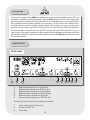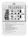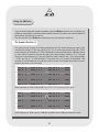
1
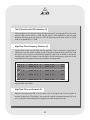
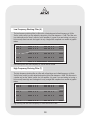
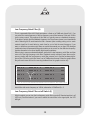
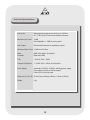
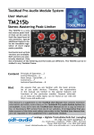
APEX NV
Schoebroekstraat 62
3583 Beringen (Paal)
BELGIUM
Tel: + 32 (0)11 28 61 91
Fax: + 32 (0)11 25 56 38
email: [email protected]
website: www.apex-audio.be
Environmental precaution
EU Directive 2002/96/EC
Remark: This notice applies only to countries within the European Union
(EU) and Norway
Electrical and electronic equipment may contain hazardous substances for
humans and their environment.
The “crossed out wheelie bin” symbol present on the device and represented above is there to remind one of the obligation of selective collection of
waste. This label is applied to various products to indicate that the product
is not to be thrown away as unsorted municipal waste. At the end of life,
dispose of this product by returning it to the point of sale or to your local
municipal collection point for recycling of electric and electronic devices.
Customer participation is important to minimize the potential affects on the
environment and human health that can result from hazardous substances
that may be contained in this product.
Please, dispose of this product and its packaging in accordance with local
and national disposal regulations including those governing the recovery
and recycling of waste electrical and electronic equipment. Contact your
local waste administration, waste collection company or dealer.
SAFETY ADVICE
CAUTION: To reduce the risk of electric shock, do not remove the cover, back or front. No user
serviceable parts inside. Refer servicing to qualified service personnel.
The lightning
flash with arrowhead symbol within an equilateral triangle, is intended to alert the user
SAFETY
ADVICE
to the presence of un-insulated “dangerous voltages” within the product’s enclosure that may be of
sufficientTo
magnitude
to constitute
a risk ofshock,
electricdoshock.
CAUTION:
reduce the
risk of electric
not remove the cover, back or front. No user ser-
viceable parts inside. Refer servicing to qualified service personnel.
The exclamation point within an equilateral triangle is intended to alert the user to the presence
of important operating and maintenance (servicing) instructions in the literature accompanying the
The lightning flash with arrowhead symbol within an equilateral triangle, is intended to alert the user
appliance.
to the presence of un-insulated “dangerous voltages” within the product’s enclosure that may be of
sufficient magnitude to constitute a risk of electric shock.
IMPORTANT
The exclamation point within an equilateral triangle is intended to alert the user to the presence of
Do not operating
modify the and
power
cord .
important
maintenance
(servicing) instructions in the literature accompanying the appliIf
the
power
cord
does
not
correspond
with the power cord you need or if it is too short to connect to
ance.
the power socket, please buy a certified power cord at a distributor.
If the power cord is damaged in any way, please replace the cord with a new certified power cord.
If the power cord is not equipped with a power plug, please follow these instructions carefully:
IMPORTANT: The wire colour codes correspond with the following:
GREEN / YELLOW:
BLUE:
BROWN:
GROUND
NEUTRAL
PHASE / LIVE
ATTENTION: This device must be grounded.
If these colours do not correspond with the symbols or colours you are using, please follow the following instructions:
The GREEN / YELLOW wire must be connected to the connector representing the letter E, the
grounding symbol ( ) or the colour GREEN.
The BLUE wire must be connected to the connector represented by the letter N or the colour
BLACK.
The BROWN wire must be connected to the connector represented by the letter L or the colour
RED.
If in any case you need to replace a fuse, please make sure that you use the same value and that
you correctly reposition the protective cover for the fuse.
IN CASE OF DOUBT, PLEASE CONTACT A COMPETENT TECHNICIAN
technician. Never try to modify the plug so that it will fit
the socket.
13) Protection of the power cable - Make sure that the
power cable is not damaged in any way, for instance
by other machines that are mounted above or below
the device.
14) Usage - for extra safety and environmental reasons we recommend disconnecting the mains if the
device is not being used for a longer period.
15) Power overload - do not overload your power lines.
Make sure that you do not exceed that maximum load
your power cabling can handle. Doing so may pose a
fire hazard.
16) External objects and liquids - make sure that no
external object and/or liquid can enter the device.
There is a risk of electrical shock and the machine may
be damaged and need servicing. Make sure that you
never poor liquids onto the device.
17) Maintenance - There is no need to open the
machine for servicing. There are no serviceable parts
in the machine.
18) Repairs - unplug the device and refer to a qualified
technician in the following cases:
a) The power cord is hot or damaged in any way.
b) An object or liquid has entered the device.
c) The device was exposed to rain or moisture.
d) The device does not seem to work properly according to the manual. Do not use more and other commands than you will find in the manual. Contact a
certified technician to help you restore the standard
commands.
e) The device has fallen or the chassis is deformed.
f) The device performs abnormally, showing signs of
malfunction.
19) Spare parts - if it is necessary to replace certain
parts, make sure that only certified parts are used or
that the used parts have the same characteristics as
the originals. Using incorrect parts can change the
device’s performance or even destroy it completely.
20) Verification - after repairs, make sure to test the
device thoroughly. Not only the functionality, but also
the safety of the device must be tested.
21) Mounting on the ceiling or wall - the device can not
be mounted on a wall or ceiling, because this will cover
the ventilation perforations causing the device to overheat.
22) Heat - the device must be kept away from all heat
sources, such as radiators, stoves or other devices
mounted in the same rack including amplifiers.
ATTENTION
1) Read instructions - all the safety instructions must be
read before the usage of the device.
2) Following the instructions - the instructions must be
a reference for all that follows.
3) Taking the signs into account - all the signs on the
device and in the manual must be taken into account.
4) Following the instructions - all the following instructions must be followed without exception.
5) Cleaning - Disconnect the power cord before all cleaning. Do not use alcohol or benzene to clean the device
nor any other liquid. Clean the device with a lightly
damp cloth.
6) Accessories - do not use accessories that are not
certified by the manufacturer or that can cause injuries.
7) Water and humidity - The device may not be used
near water, for instance near a bath, river, damp room,
swimming pool, or any similar environment.
8) Stands - do not use an unstable stand. It can fall and
injure someone and the equipment may be damaged.
Do not use anything other than stands and mounting
systems that are certified by the manufacturer or that
are sold with the device. Make sure that the mounting of
the device is done properly. Observe all safety instructions provided by the the manufacturer.
9) A device mounted in a mobile rack must be treated
with care. A sudden stop or pushing it too roughly, in
combination with a rugged surface can make the rack
tip and so injure someone or damage the equipment
that is in the rack.
10) Ventilation - The perforations in the casing of the
device are there to make sure that the device can operate at the correct temperature and cooling of the interior be guaranteed. You must make sure that these
openings are not blocked in any way such as by panels
or tissues or papers. The device should not be mounted
in a closed case where no passive or active ventilation
is possible.
11) Power - you must connect the device to a power line
described in the manual or at the back of the device. If
you are not sure that the unit as supplied is correct for
your supply voltage, please contact a technician or your
local reseller.
12) Grounding and polarisation - this device can be
equipped with a polarised power connector that only
connects one way round which can provide additional
safety features. If you are unable to put the power plug
into the socket, try it again the other way. If you do not
succeed to put the power plug into the socket, ask a
Introduction
Thank you for buying the Apex dBQzero equaliser. Apex is manufacturing equalisers since 1991 and
has build up a reputation of outstanding quality. With the dBQzero we have tried to offer a high-quality
dual channel graphic equaliser with some extra filters for a very affordable price. In our humble opinion
this is probably the best sounding equaliser in its price range. The unit consist of two identical channels. Each channel consists of a graphic equaliser section with 30 bands, a frequency selectable high
pass filter with in/out switch, high and low shelving filters, two notch filters with selectable frequencies
and in/out switches, an overall level control and LED VU meter with signal LED and clip LED. If you are
used to working with graphic equalisers you will probably be able to operate the unit straight out the box
without further reading of the manual. However to get the most out of the dBQzero, we invite you to read
the rest of this manual.
DESCRIPTION
REAR PANEL
8
7
1:
2:
3:
4:
5:
6: 6
9
Balanced input of channel A on XLR-female
Balanced input of channel A on TRS 6,35 Jack
Balanced input of channel A on Screw Terminal
Balanced output of channel A on Screw Terminal
Balanced output of channel A on XLR-male
Balanced output of channel A on TRS 6,25 Jack
The identical layout is used for the connections of channel B
7:
8:
9:
Power switch, turns the unit on or off
AC inlet 100-240 V AC
Fuse Holder
5
4
3
2
1
FRONT PANEL
1
4
1:
2:
3:
4:
5:
6:
7:
8:
9:
10:
11:
12:
13:
5
2
3
8
6
7
9
10
13
11
14
Graphic equaliser section, 30 bands on ISO frequencies
Input level control
6/15dB switch with LED indication changes the maximum boost/attenuation of the graphic Eq
High Pass Filter frequency selection
High Pass Filter on/off switch with LED indication
Low Frequency Shelving filter
High Frequency Shelving filter
Low Frequency Notch filter frequency selection
Low Frequency Notch filter on/off switch with LED indication
High Frequency Notch filter frequency selection
High Frequency Notch filter on/off switch with LED indication
Equaliser Bypass switch with LED indication
LED VU-meter and Clip LED
The identical layout is used for the connections of channel B
14:
12
Power on/present indication LED
Before use...
Mounting the dBQzero in a rack or flight case
The dBQzero can be mounted in a standard 19inch rack or flight case via the four holes in
the front panel. Use the correct screws (not delivered) and fix the unit with all four screws.
For normal use no extra support is needed, but in more extreme conditions “on the road” we
advise to support the unit underneath the back. The dBQzero will not run very hot in normal
operating conditions, but again, under extreme hot temperature conditions we advise you to
leave 1U of ventilation space above and under the unit.
Connecting the dBQzero
Connect power to the dBQzero via the Power inlet (8), use the power cord provided with
the EQ, or get a power cord suitable for use in your country. The dBzero has an automatic
switchable power supply, which accepts a wide range of AC power: from 100V to 220V. Do
not connect the EQ to a 380V power source!!!!!
Never replace the fuse in the Fuseholder (9) with a type different than indicated on the
back panel.
All audio inputs and outputs of the dBQzero are balanced and use common cabling rules:
XLR: pin 1 = GND, pin 2 = HOT, pin 3 = Cold
JACK: TIP = HOT, RING = COLD, SLEEVE = GND
When making connections in a fixed installation you can gain time and money by directly connecting your cables to the screw terminal connectors.
Turn the unit on via the mains power switch (7), there will be a very short delay before the
unit will start working and the equaliser circuit is switched into circuit to avoid loud cracks and
bangs. When no power is present or the mains power switch is off, the unit will be/go in hardbypass mode, hereby linking the inputs to the outputs so that the signal goes true the unit
unaltered.
Using the dBQzero
If you are used working with graphic equalisers, using the dBQzero will pose you no problem; you
will just be surprised by its accuracy and musicality. However if you like to know the fine details of
this equaliser, we invite you to read on.
The two channels of the dBQzero are identical so only one channel is described.
The Graphic Section (1)
The graphic section consists of 30 faders adjusting the 30 ISO centered frequency bands (1/3rd
Octave) with constant Q. But what exactly is this “Q”: Q can be determined as the ratio of filter
centre frequency to bandwidth ( Q = f/Bw). Bandwidth is measured between the 3-dB down points
on either side of resonance (and usually where the phase has been shifted ± 45°). If a tuned
circuit has a centre frequency of 1 kHz and 3-dB down points at 900Hz and 1.1kHz, the bandwidth
= 200Hz and the Q = 5 (1000Hz/200Hz). The greater the Q, the smaller the bandwidth. With
constant Q, the bandwidth (at the 3-dB down points of each of the graphic filters stays constant,
whatever the boost or cut of that filter.
20
15
10
5
dB 0
-5
-10
-15
-20
-25
-30
-35
-40
25 31 40 50 63 80 100 120 160 200 250 315 400 500 630 800 1k 1k25 1k6 2k 2k53k15 4k 5k 6k3 8k 10k12k5 16k 20k Hz
centre frequency of 1kHz, boost of 5dB (all images taken from the Apex IntelliQ digital system optimiser).
20
15
10
5
dB 0
-5
-10
-15
-20
-25
-30
-35
-40
25 31 40 50 63 80 100 120 160 200 250 315 400 500 630 800 1k 1k25 1k6 2k 2k53k15 4k 5k 6k3 8k 10k12k5 16k 20k Hz
centre frequency of 1kHz, boost of 12dB (the bandwidth at the -3dB points stays the same).
All analogue equalisers will introduce some phase shift when used and different equaliser bands
will also interact when used together. A graphic equaliser can be considered as a combination
of 30 distinct equalisers with fixed centre frequencies and in the case of the dBQzero with a
constant Q factor. You can only change the gain/attenuation of the filters. This should make it
clear why some equalisers (like the dBQzero) sound better and more accurate than others. The
centre frequencies should be very precisely set; the Q factor really constant and similar for all
bands or the interaction between all those filters will create an unpredictable result.
When using a graphic filter for adjusting your sound, start from the lower frequencies and work
your way up to the higher ones (work from left to right). Most individual sounds consist of a
fundamental frequency and more or less harmonics depending on the nature and/or origin of
that sound. When working from left to right you’ll make sure to first touch the fundamentals and
when altering those you will also act on their harmonics. A good example is mains hum (50Hz
or 60Hz), this is mostly a dirty sound with some harmonics: if you work from right to left you will
try to get rid of all the harmonics first to finally get to the fundamental. When working from left to
right you will get to the fundamental first and take out more or less some of the harmonics, so
you will actually use less correction. And with equalising: less is better.
Another good advise is: it is better to cut than to boost. When boosting frequencies or frequency
bands you will reduce the overall headroom of your system. If for example you think there is a
lack of high frequencies in your sound, you can either push those frequencies or you can cut
some of the low frequencies.
And as a last advice: avoid extreme settings between adjacent bands, they will create big phase
shifts. Try to make your equalising curve as smooth as possible.
The Level Control (2)
This is an overall gain control, which controls the input level.
The purpose of this control is to be able to adjust the level according to the used overall equalisation. If you have boosted a lot of frequencies, your overall signal will be much hotter and could
overdrive the equaliser or the following equipment, adjust your signal with the level control. The
same goes of course if you have cut a lot of frequencies, use this control to boost the overall
level back to normal.
10
The 6/15 switch with LED indication (3)
Via this switch you can change the scale (maximum boost/cut) of the graphic EQ. In its normal
position (LED out) the scale is +/- 6dB: use this scale for minor adjustments but with great
precision. When you push the button the LED will light and you will have access to the full
scale of the graphic EQ: +/- 15dB.
High Pass Filter Frequency Selection (4)
Via this rotary control you can adjust the high pass filter. This is a filter with a fixed slope of
12dB/octave; use the control to adjust the cut-off frequency between 20Hz and 250Hz. With
this section you can get rid of unwanted low frequency noise such as rumble or microphone
handling noise. Again: it is better to use this filter to cut-off low frequency noise than to use
several bands of the graphic section since less filters is always better.
20
15
10
5
dB 0
-5
-10
-15
-20
-25
-30
-35
-40
25 31 40 50 63 80 100 120 160 200 250 315 400 500 630 800 1k 1k25 1k6 2k 2k53k15 4k 5k 6k3 8k 10k12k5 16k 20k Hz
high pass filter set at 50Hz
High Pass Filter on/off switch (5)
When the accompanying LED is out, the filter is not in the signal path. Push the switch to
activate the filter (the LED will light). You can use this switch to compare between filter in en
out to verify if the used setting thus not degrade your musical signal too much.
11
Low Frequency Shelving Filter (6)
The low frequency shelving filter is a filter with a fixed slope and a fixed frequency at 100Hz.
Via the rotary control you can adjust the boost/cut of the filter between +/- 9dB. This filter acts
in a similar way as the “bass” control of a hi-fi amplifier; it is great if you are lacking (or having a
bit too much) some low end. And again it is only a single filter compared to a number of graphic
faders.
20
15
10
5
dB 0
-5
-10
-15
-20
-25
-30
-35
-40
25 31 40 50 63 80 100 120 160 200 250 315 400 500 630 800 1k 1k25 1k6 2k 2k53k15 4k 5k 6k3 8k 10k12k5 16k 20k Hz
low shelving filter with fixed frequency of 100Hz and cut of 9dB
High Frequency Shelving Filter (7)
The high frequency shelving filter is a filter with a fixed slope and a fixed frequency at 14kHz.
Via the rotary control you can adjust the boost/cut of the filter between +/- 9dB. This filter acts in
a similar way as the “treble” control of a hi-fi amplifier; it is great if you are lacking (or having a
bit too much) some high end. And again it is only a single filter compared to a number of graphic
faders.
20
15
10
5
dB 0
-5
-10
-15
-20
-25
-30
-35
-40
25 31 40 50 63 80 100 120 160 200 250 315 400 500 630 800 1k 1k25 1k6 2k 2k53k15 4k 5k 6k3 8k 10k12k5 16k 20k Hz
high shelving filter with fixed frequency of 14kHz and boost of 5dB
12
Low Frequency Notch Filter (8)
This is a parametric filter with 2 fixed parameters: a fixed cut of 30dB and a fixed Q of 2. You
can select the centre frequency of the low frequency notch filter between 20Hz and 1200Hz
via the rotary control. The purpose of this filter is to quickly remove a feedback frequency.
To be able to quickly find the feedback frequency the Q has been chosen to an intermediate
value. Reducing this Q would make the filter narrower (thus avoiding cutting out too much
musical signal) but it would take too much time for you to find the exact frequency. If you
want or need more accurate notch filters we would recommend you our Apex PE analogue
models who have full parametric filters who enable you to zoom in on the offensive frequency.
Another alternative is our Apex IntelliQ digital system optimiser.
When trying to remove unwanted feedback, start with the low frequency notch filter and then
move on to the high frequency notch filter. Feedback mostly consists of more than one frequency, starting with the low frequency notch filter assures you to find the fundamental frequency first. Since the notch filter have a cut of 30dB and a narrower Q than the graphic filters
they are much more efficient for removing feedback than the graphic section only.
20
15
10
5
dB 0
-5
-10
-15
-20
-25
-30
-35
-40
25 31 40 50 63 80 100 120 160 200 250 315 400 500 630 800 1k 1k25 1k6 2k 2k53k15 4k 5k 6k3 8k 10k12k5 16k 20k Hz
Notch filter with centre frequency at 140Hz, attenuation of 30dB and Q = 2
Low Frequency Notch Filter on/off Switch (9)
With this switch you can turn the low frequency notch filter on and off. Standard position is off
(LED out). Push the button if you want to switch the notch filter in the signal path, the LED
will light.
13
High Frequency Notch Filter (10)
This Filter is identical to the Low Frequency Notch Filter except that you can select a higher
centre frequency via the rotary control: between 800Hz and 20kHz.
High Frequency Notch Filter on/off Switch (11)
With this switch you can turn the high frequency notch filter on and off. Standard position is off
(LED out). Push the button if you want to switch the notch filter in the signal path, the LED will
light.
Equaliser Bypass Switch (12)
The bypass switch will connect the input straight to the output, thus bypassing all equalising.
In case of Power Failure the bypass is automatically activated
LED-VU meter and Clip LED (13)
There is an eight-section VU meter and one signal LED with a scale in 3dB steps which measures the signal on the output after all the filter sections. A separate Clip LED will light when you
have reached the maximum level of the dBQzero and no more headroom is left, this Clip
circuit monitors the signal at three different points in the signal path: input, post level control
and post filters.
If the clip LED lights verify your EQ setting but do not forget to bypass all the filters and make
sure your input signal is correct. Check this before the start of any show too make sure you are
feeding the unit with a correct level signal.
Power on/present indication LED (14)
When the power switch on the backside of the unit is on, and mains power is present, this LED
will light to assure you. In case of a power failure or if you have turned off the mains power
switch on the back of the unit, the unit will be/go in hard-bypass mode, hereby linking the inputs
to the outputs so that the signal goes true the unit unaltered.
14
Technical Specifications
Line Inputs:
Balanced high impedance line level input, 10kOhms
On ¼” TRS -jack, XLR and screw terminal connector.
Maximum Input Level: +20dB
Gain adjustable +/- 10dB via rotary control
Line Outputs:
Electronically balanced low impedance outputs
Maximum Output Level: +21dB into 600 Ohms
Noise:
Crosstalk:
92dB, 20Hz-20kHz, A-weighted
Better than 80dB
THD:
< 0,005%, 20Hz - 20kHz
Frequency Response: +/- 0,5 dB 20Hz - 20kHz, all controls flat
Power Supply:
Auto-detect 110/230V - 50/60Hz, switching power supply
Power switch and fuse on the back panel
Power LED on the front panel
Dimension (H x W x D): 3U rack Case x 483mm (19inch) x 133mm (5,25inch)
Weight:
4 kg
15
16
17