1
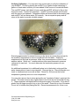
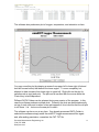
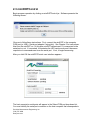
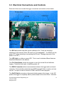
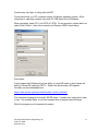
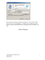
Precision Measurement Engineering, Inc. • www.pme.com
User’s Manual
2014
Precision Measurement Engineering, Inc.
(760) 727-0300
www.pme.com
1
Warranty
1-YEAR LIMITED WARRANTY ON miniDOT HARDWARE
Precision Measurement Engineering, Inc. (PME) warrant that the miniDOT Logger
shall be free of defects in workmanship and materials, under normal use, for a period
of one year from the date of shipment. This warranty is made only to the original
purchaser. In the event a miniDOT Logger covered by this warranty fails to operate
according to our published specifications, then return it freight pre-paid to PME or an
authorized Service Provider. PME will repair the unit at no charge to the customer
and bear the cost of return shipment. Carefully pack all components, as the customer
is responsible for any freight damage.
This warranty does not apply to services or consumable / expendable items (such as
batteries, fuses and ropes) required for general maintenance. Equipment
manufactured by other companies (such as meteorology sensors, solar panels, etc)
are warranted only to the limit of the warranties provided by their original
manufacturer.
PME makes no warranty, either expressed or implied, that the sensors will be
operable after they are exposed to adverse environmental conditions, such as biofouling, oil fouling, freezing temperatures or others.
This warranty is void if, in our opinion, the miniDOT Logger has been damaged by
accident, mishandled, altered, or repaired by the customer, where such treatment has
affected its performance or reliability. In the event of such treatment by the customer,
costs for repairs plus two-way freight costs (no COD shipments will be accepted) will
be borne by the customer. In such cases, an estimate will be submitted for approval
before repair work is started. Items found to be defective should be returned to PME
carefully packed, as the customer will be responsible for freight damage.
Incidental or consequential damages or costs incurred as a result of the product
malfunction are not the responsibility of PME.
For all warranty or non-warranty returns please obtain, complete, and submit a RMA
to PME. This RMA form may be obtained at
http://www.pme.com/HTML%20Docs/RMAform.html.
After submission of this form, then PME will respond with a RMA number. Please
place this number on all shipments and related communications.
Precision Measurement Engineering, Inc.
(760) 727-0300
www.pme.com
2
Safety Information
BURSTING HAZARD
Should water enter the miniDOT Logger and come into contact with the enclosed
batteries, the batteries may generate gas causing the internal pressure to increase.
This gas will likely exit via the same location where the water entered, but not
necessarily. The miniDOT Logger is designed to release internal pressure as the end
cap is unscrewed, prior to the disengagement of the end cap threads. If internal
pressure is suspected, then treat the miniDOT Logger with extreme caution.
Revision History
Date
20-JUL-2010
02-FEB-2011
14-MAY-2011
06-JUN-2011
08-JUN-2011
14-JUN-2011
16-JUN-2011
28-JUN-11
17-OCT-2011
14-DEC-2011
15-DEC-2011
19-DEC-2011
20-DEC-2011
10-JAN-2012
12-JAN-2012
19-JAN-2012
06-FEB-2012
10-FEB-2012
17-FEB-2012
14-MAY-2012
07-JUN-2012
17-JUL-2012
05-SEP-2012
10-SEP-2012
09-JAN-2013
21-MAR-2013
18-JUN-2013
17-JUL-2013
24-JUL-2013
05-NOV-2013
11-NOV-2013
03-MAR-2014
06-MAY-2014
16-JUL-2014
29-SEP-2014
Revision Description
Initial document
Revised to show better Dataturbine screen, added Vega, misc changes
Extensively modified due to simplification of logger software
Modified to describe startup with no 3 flashes if no CAL.TXT file found. This to
be consistent with logger software change
Added o-ring and SD card information, multiple plot info
Minor wording changes; coin cell discharge description changed
Added no backspace instructions to command description
Now supplying cal.txt file
Removed Export folder from miniDOT Plot software
Corrected reference to section 2.9 to refer to section 3.9, added Sec 3.11 SD
Card
Corrected 19200 baud to 9600 baud in Appendix
Corrected command instruction giving example for setting time
Corrected correction of time instruction
Added corrective action to flash description
Added miniDOTControl information
Added instructions concerning battery selection
Updated for new Rev 2.09 firmware
Revised to eliminate CAL.txt file and support new serial controls
Revised to eliminate Hyperterminal instructions.
Incorporated elevation/pressure entry in miniDOTPlot
Added enhanced description of time zones and world time zone map.
Added SD removal only with power off instructions
Revised for new AA batteries and for stereo plug for RS232
Added picture of battery voltage measurement
Added amount of SD card useage to battery life table
Reworded miniDOTControl set time to describe Rev 1.06 miniDOTControl
Reworded driver copy to say where to copy it
Added words concerning opening and closing
Added yeast instructions, removed sodium sulfite
Added formatter download, reworded serial port driver to jspWin
Reworded Chapter 2 Software installation
Timezone entry in miniDOTPlot removed
Included Copper Mesh Instructions
Added instructions for the SD card retainer
Added Storage When Not in Use to section 1.2
Removed the Copper Mesh Instructions
Precision Measurement Engineering, Inc.
(760) 727-0300
www.pme.com
3
CONTENTS
Chapter 1 Quick Start
1.1 The Quickest Start Possible
1.2 A Few Details
Chapter 2 Software
2.1 Overview and Software Installation
2.2 miniDOTPlot
2.3 miniDOTControl
Chapter 3 miniDOT Logger
3.1
3.2
3.3
3.4
3.5
3.6
3.7
Overview
Opening and Closing the Logger
Electrical Connections and Controls
File Close Button
Battery Replacement
File Management
SD Card
Precision Measurement Engineering, Inc.
(760) 727-0300
www.pme.com
4
Chapter 1: Quick Start
1.1 The Quickest Start Possible
Your miniDOT Logger has arrived completely ready to go. It is set to measure
temperature and oxygen concentration once every 10 minutes and record 4 files of
measurements daily. You need only turn on the power and deploy the logger. In this
condition the miniDOT Logger will operate for most of a year before the internal
battery is expended.
At the end of the deployment period you need only to open the logger, press the File
Close button, switch off the power, and remove the SD card. Your temperature and
oxygen concentration measurements, together with a time stamp indicating the time
the measurement was made, are recorded in text files in the DATA directory on the
SD card. These files can be copied from the SD card onto any host computer.
Follow these steps to start the deployment, logging DO & T once each 10
minutes:
1) Open the miniDOT Logger by unscrewing the white housing from the black end
cap. Remove the housing completely. Inside you will see the circuit pictured
below:
Precision Measurement Engineering, Inc.
(760) 727-0300
www.pme.com
5
2) Slide the power switch to the ON position. The LED will flash once. The miniDOT
will now delay to the start of the next minute. Observe the LED for up to 90
seconds. Sometime during this period it will flash 5 times indicating that logging
has begun. If it flashes continuously, then see Section 1.2 of this manual.
3) Inspect the o-ring seal for debris.
4) Close the miniDOT Logger by screwing the white housing back onto the black end
cap.
5) Deploy the miniDOT Logger.
Follow these steps to end the deployment
1) Recover the miniDOT Logger
2) Clean and dry all accessible surfaces except the ‘foil’.
3) Open the miniDOT Logger by unscrewing the white housing from the black end
cap. Remove the housing completely, taking care that water does not drip onto
interior surfaces of circuits or other items inside the logger.
4) Press the File Close button. The LED should begin continuous flashing.
5) Slide the power switch to the OFF position.
6) Unscrew the SD card retaining attachment. Remove the SD card by pushing
down on it so the card is ejected. Use a card reader and a host computer to copy
the files located in the DATA directory onto the host computer. These text files
contain the measurements. (Note: SD card is not “hot swappable”. You MUST
turn the power OFF before removing or reinserting the SD card. Damage may
result if the power is not OFF.)
7) (Optionally) Run PME’s miniDOTPLOT.jar program to see a plot of dissolved
oxygen, temperature and oxygen saturation, and to produce a concatenated file
containing all the measurements.
Remove the batteries if storing the miniDOT Logger for extended periods.
1.2 A Few Details
The previous section gives instructions for sampling at 10-minute intervals. However
there are a few additional details that will enhance use of the miniDOT Logger.
Sampling Interval – The miniDOT Logger measures and records dissolved oxygen
concentration and temperature at equal time intervals. The default time interval is 10
minutes. If a formatted SD card is placed in the miniDOT Logger and the power is
turned on, then the logger will record every 10 minutes. However, it is also possible
to instruct the miniDOT Logger to record at different intervals. This is accomplished
by running the miniDOTControl.jar program supplied with the miniDOT. Sample
intervals must be 1 or more minutes and must be less than or equal to 60 minutes.
Sample intervals outside this range will be rejected by miniDOTControl. (miniDOT
can sample as rapidly at 10 second interval if properly instructed. Contact PME.)
Precision Measurement Engineering, Inc.
(760) 727-0300
www.pme.com
6
Please refer to Chapter 2 for instructions on operating the miniDOTControl program.
Sample Time – The miniDOT Logger records the time that each measurement of
dissolved oxygen and temperature is made. It does this based on an internal clock.
When your miniDOT Logger arrives it is set by PME to UTC (formerly known as
Greenwich mean time (GMT)). Subsequent PME software implements conversion to
local time. The miniDOTControl.jar program allows you to set miniDOT time based
upon the host computer’s time. This is automatically translated to UTC based on
settings within the host computer.
The miniDOT Logger internal clock will drift in the <10 ppm range (< about 30
seconds/month) so you should plan to reset it occasionally.
Please refer to Chapter 2 for instructions on operating the miniDOTControl program.
File Information – The miniDOT Logger software creates 4 files daily. The number
of measurements in each file will depend upon the sample interval. Files are named
by the time (Unix epoch 1970) that the file is opened based on the logger’s internal
clock and expressed in hexadecimal format.
Cleaning the Sensing Foil –The sensor can be cleaned at regular intervals
depending on the fouling condition at the site. The cleaning procedure of the sensor
spots should be done with caution so that the protective coating is not removed. If the
fouling is calcareous it can normally be dissolved with household vinegar. Another
substance that can be used is commercially called muriatic acid, which is a 5% HCl
solution (dilute solution by 50% should be tested to see how well it dissolves growth
before using a stronger concentration).
If needed, the Optode can be submerged in vinegar/HCl over night, or longer. If the
marine growth remains, then use Q-tips to gently wipe it off after it has been softened
by soaking in vinegar/HCl. After cleaning the sensor it should be rinsed well in clean
tap water before storing or reuse. You can also use methanol and ethanol for the
cleaning procedure. Do not use other organic solvents such as acetone, chloroform,
toluene since these and others will damage the foil.
The sensor membrane can also be cleaned using a 3% H2O2 solution or rinsing it
with ethanol.
The delrin case of the miniDOT Logger can be gently scrubbed.
Precision Measurement Engineering, Inc.
(760) 727-0300
www.pme.com
7
AA Lithium Battery Life – The miniDOT Logger consumes battery power mostly
from the measurement of dissolved oxygen, but also slightly from simply keeping
track of time, writing files, sleeping, and other activities. The following table presents
the approximate endurance of the miniDOT Logger when powered by the Energizer
L91 AA lithium / ferrous disulfide batteries supplied by PME:
SAMPLE INTERVAL
(minutes)
Main AA Battery Life
(days of sampling)
Number of
Samples
1
10
60
180 days
270 days
300 days
259,000
38,000
7,200
Fraction of
SD Card
Used
(%)
0.6
0.1
0.06
Keep a general record of miniDOT Logger number of samples. It is not possible to
accurately tell the charge state of a lithium battery from measurements of its terminal
voltage. If you have a general idea of the number of samples already obtained on a
battery, then you can make a guess as to how many more samples remain.
The numbers in the table above are at the time of this writing only estimated based
on published battery capacity. However, these AA batteries are easily available and
relatively inexpensive compared to the cost of the miniDOT. PME suggests you
replace the batteries as often as possible. Monitor terminal voltage. You cannot tell
from terminal voltage how long the battery will last, but you can tell if it will die
sometime really soon. The Low Drain Performance plot below gives an estimate of
terminal voltage for both lithium and alkaline batteries. Your measured voltage will be
2X what is shown below since there are two batteries in series within the miniDOT.
You can operate batteries down to about 2.4 Volts (for two in series). Measure the
series voltage as shown in the picture below. Your batteries are dead if this
measurement is less than 2.4 Volts.
Precision Measurement Engineering, Inc.
(760) 727-0300
www.pme.com
8
You may also use alkaline AA batteries such as Duracell Coppertop. They will not
last nearly as long, especially at low temperatures, but will likely be adequate for
several weeks at 10-minute interval.
When replacing batteries use only fresh batteries. Don’t mix battery types. If one
battery differs in type or charge level from the other and the miniDOT runs them to full
discharge, one battery may leak.
Err on the side of caution when planning your deployment.
The recommended battery is Energizer L91. See this link for information including
performance at low temperatures:
http://data.energizer.com/PDFs/l91.pdf
The figure below gives a very general idea of terminal voltage vs lifetime. Service life
in hours is incorrect since miniDOT draws far less than 50 mA continuously but the
general shape of the voltage vs time gives an estimate of life remaining. This plot is
taken from the manufacturer’s specification. The plot is for a single battery. Double
the voltages shown to give the terminal voltage as measured in the picture above.
Coin Cell Battery Life – The miniDOT Logger uses a coin cell for backup of the
clock when the power is switched off. This coin cell will supply roughly 2 years of
clock operation, but this is only required if the main power is off. Should the coin cell
discharge it must be replaced. Contact PME.
Recalibration – The miniDOT Logger will maintain its calibration without the
necessity of adjustment by the user. Loggers should be returned to PME for
recalibration. We suggest that this be done every ½ million samples.
Precision Measurement Engineering, Inc.
(760) 727-0300
www.pme.com
9
O-Ring and Seal – When the cover is screwed on, it passes along the o-ring located
in the end cap several revolutions. Keep this o-ring lightly lubricated with silicone
grease or oil compatible with buna-N o-ring material.
When the miniDOT Logger is opened after deployment, a small number of water
drops are deposited on the inner surface of the o-ring. When the pressure housing is
screwed back on these drops become trapped inside the miniDOT Logger. Be sure
to carefully dry the o-ring and adjacent surfaces (especially underneath) prior to
closing the miniDOT. Re-lube the o-ring at this time.
SD Card – The SD card is secured with a retaining attachment. This is to keep the
card from potentially being ejected from its socket if the miniDOT Logger is dropped
on its pressure housing end. The logger will be unable to log should this occur. PME
recommends that the SD card be secured by the retaining attachment. This
attachment should be secured by the provided screw and lock washer. To remove
the SD card, simply unscrew the retaining attachment from the miniDOT chassis.
The SD card is not “hot swappable”. You MUST turn the power OFF before removing
or reinserting the SD card. Damage may result if the power is not OFF. Use only 2
GB SD cards.
LED Indications – The miniDOT Logger performs various tests as it begins logging
operations. If any test fails the software flashes the LED light and re-conducts the
test. In general if a test fails once it will continue to fail and the LED light will
continue to flash. The following table gives the number of flashes and the reason
these flashes appear.
LED
Flash #
1
2
3
4
5
Reason
Corrective Action
Normal. Presented immediately
after power is switched on.
Indicates that the CPU has
started its program.
Error. No SD Card or SD card
not completely plugged in.
None required. Normal operation.
Error. Requested sampling
interval less than 1 minute or
greater than 1 hour.
Error. Clock not initialized.
Normal, presented once after
roughly one minute, indicating
that the miniDOT Logger is
starting logging operation.
Precision Measurement Engineering, Inc.
(760) 727-0300
www.pme.com
Plug SD card correctly. Install new
SD card. Re-format SD card (Sec
3.7). Turn power off before
unplugging/plugging SD card
Contact PME
Reset clock using miniDOTControl
program (Sec 2.3)
None required. Normal operation
10
Verifying Calibration – You may from time to time want to verify the calibration of
your miniDOT. Do this by placing the miniDOT in a 5 gallon bucket containing 4
gallons of fresh water to which you have added 2 fluid ounces of household bleach.
The miniDOT sensor end (black) is heavy and the miniDOT will tend to flip so that
this end is down. Prevent this somehow. miniDOT must be placed in the bucket
with the sensor end upwards. Otherwise bubbles will accumulate in the sensing end
and miniDOT will not sense water DO correctly. Use an aquarium pump and air
stone in the water to provide a bubble stream.
Record measurements for several hours or a day but in any event long enough for
the miniDOT temperature to come to equilibrium with the water. During the
experiment find the local air pressure, either from measurements or from a local
weather station. Watch out... weather stations often report barometric pressure
referenced to sea level. You must determine the barometric pressure at your
elevation.
An additional experiment is to additionally place ice in the bucket, mixing until the
water temperature is close to zero degrees. Remove the ice. Place the bucket on a
towel or cardboard and cover with a towel. Record for 24 hours as the bucket
temperature gradually returns to room temperaure.
You may also remove the air stone and gently mix 2 packets of baker’s yeast into the
bucket. The water must be only slightly warm to the touch but not more than 30 deg
C. These organisms will deplete all the dissolved oxygen in the water. Cut a disc of
plastic film just large enough to lay on top of the water. Place this on top of the water.
Do not stir or bubble after placing the film. Record measurements for a hour or so.
Precision Measurement Engineering, Inc.
(760) 727-0300
www.pme.com
11
Use miniDOT plot to examine the measurements. Saturation values should be very
close to 100%, depending upon the accuracy that you have determined barometric
pressure. If you placed ice in the bucket then saturation values will still be 100% but
you will see the DO concentration and temperature change greatly.
The recorded data when using yeast should show 0% saturation and 0 mg/l dissolved
oxygen concentration. In practice miniDOT often reports slightly positive values, but
within the accuracy of the miniDOT.
Closing and Opening – Close and open miniDOT like you would a flashlight: open
by unscrewing the white cylinder from the black end cap. Close by screwing the
white cylinder on. When closing, do not tighten the white cylinder. Just screw it on
until it makes contact with the black end cap. See Chapter 3 for more instructions.
Please DO NOT remove the stainless steel screws in the black end cap. There are
no user serviceable parts here. If the screws are removed you will damage the
miniDOT and it will have to be returned for repair.
Storage When Not in Use – Remove the batteries. Keep the black end covered with
the cap supplied by PME. If the cap is lost, cover the end with aluminum foil. There
may be an calibration effect of ambient lighting so attempt to keep ambient light from
reaching the sensing foil as much as possible.
Precision Measurement Engineering, Inc.
(760) 727-0300
www.pme.com
12
Chapter 2: Software
2.1 Overview and Software Installation
The miniDOT Accessory Kit includes software to concatenate and display miniDOT
Logger data files, miniDOTPlot.jar, and to control the miniDOT, miniDOTControl.jar.
miniDOTPlot displays plots of miniDOT measurements. miniDOT Control enables
selection of sample interval and setting the miniDOT internal clock.
miniDOT software operates on a Windows PC computer. Both 32 and 64 bit
computers are supported.
Software is supplied on CD or in a zip file. Copy or unzip to any folder on your
computer’s hard drive. The software will contain these files and folders:
Name
miniDOTPlot.jar
miniDOTControl.jar
MoreMemory.bat
jspWIN.dll
32 Bit PC Serial
Driver
64 Bit PC Serial
Driver
Manual
xxxxxxxxx.pdf
Type
Java
executable
Java
executable
Windows
batch
Windows
dll
Folder
Function
Plot miniDOT measurements, concatenate these
into CAL.txt file
Set time, set sample interval.
Folder
Contains 64 bit version of jspWIN.dll
PDF
document
This manual
Invoke miniDOTPlot with more memory for really
large measurement sets
Interface java to Windows COM port. The
default is 32 bit.
Contains 32 bit version of jspWIN.dll
miniDOTPlot and miniDOTControl are Java language programs that require the host
computer to have the Java Runtime Engine V1.6 (JRE) or later installed. This engine
is commonly required for internet applications and will likely already be installed on
the host computer. You can test this by running miniDOTPlot. If this program
displays its graphical user interface then the JRE is installed. If not then the JRE can
be downloaded via internet from
http://www.java.com/en/download/windows_xpi.jsp
miniDOTControl communicates with the host computer’s serial port. It requires a
serial port driver, jspWin.dll. The jspWin.dll in the files supplied is the 32 bit version.
If your computer is a 64 bit computer, delete jspWin.dll. In its place copy the
jspWin.dll from the 64 Bit PC Serial Driver folder. The correct (32 or 64 bit) jspWin.dll
must be present in the same folder as miniDOTControl.
Precision Measurement Engineering, Inc.
(760) 727-0300
www.pme.com
13
If your computer does not have a serial port (these are called COM ports on Windows
computers) you must supply a serial-to-USB adapter. These can be purchased from
PME or from some other source. These adapters usually require that you install a
driver. For PME’s adapter follow instructions supplied with the adapter.
2.2 miniDOTPlot
Begin program operation by clicking on miniDOTPlot.jar.
When miniDOTPlot runs it presents the screen shown below.
miniDOTPlot reads and concatenates the files recorded by the miniDOT Logger. The
software will also compute oxygen saturation from dissolved oxygen measurements.
To do this software must know the air pressure and salinity. It calculates air pressure
based on elevation of the water surface above sea level or uses the barometric
pressure you enter if Barometric Pressure is selected. If elevation is entered, no
compensation for weather-induced barometric pressure variation is made. Enter
elevation or barometric pressure. Enter water salinity.
Select the folder that contains the files recorded by miniDOT. These files have file
names similar to 51BA1F98.txt. This could be the DATA folder on the SD card from
the miniDOT or it could be any folder on your computer’s hard drive where you
copied the miniDOT files. This folder must NOT contain any other files besides
miniDOT data files.
Press ‘Process’ to begin program operation.
The software reads all miniDOT Logger data files in the import folder. It
concatenates these, computes oxygen saturation and compensates for salinity, and
writes the result into a file named CAT.TXT in the same folder where it finds the
miniDOT data files. This is a text file and looks similar to the following:
Precision Measurement Engineering, Inc.
(760) 727-0300
www.pme.com
14
The software also produces a plot of oxygen, temperature, and saturation vs time.
You may zoom this plot by drawing a square from upper left to lower right (click and
hold left mouse button) that defines the zoom region. To zoom completely out,
attempt to draw a square from lower right to upper left. Right click on the plot for
options such as copy and print. The plot can be scrolled with the mouse while the
Control key is held depressed.
Different DATA Folders can be selected during one session of the program. In this
case the software produces multiple plots. Presently the plots are presented exactly
on top of each other and so when a new plot appears it is not obvious that the old plot
is still there. It is. Just move the new plot to see it.
The software can be re-run at any time. If an already processed DATA Folder is
selected the software simply reads the miniDOT Logger measurement files again
and, after asking permission, overwrites the CAT.TXT file.
Precision Measurement Engineering, Inc.
(760) 727-0300
www.pme.com
15
2.3 miniDOTControl
Begin program operation by clicking on miniDOTControl.jar. Software presents the
following screen:
Be sure to follow these instructions. First, connect the miniDOT to the computer
COM port (or USB – Serial port adapter if using this). See Chapter 3 for instructions.
Next turn the miniDOT on. At this time miniDOT determines if it is connected to the
serial port or not. If connected, it illuminates the LED continuously and it becomes
responsive to commands sent over the serial port. If not, it begins measuring.
After you click OK the miniDOTControl user interface appears.
The host computer’s serial ports will appear in the Select COM port drop-down list.
You must identify the serial port connector on the host computer that corresponds to
Precision Measurement Engineering, Inc.
(760) 727-0300
www.pme.com
16
the list entry. Most lap-top computers will not have a serial port. If this is the case a
serial port can be added by purchasing an inexpensive serial-to-usb converter. See
manufacturers instructions for installation of this device. PME sells a kit containing
this converter.
Click on the Connect button. The software will contact the logger. If the connection
is successful the button will turn green and display “Connected”. The Serial Number
and other parameters will be filled in from information taken from the miniDOT.
If the host computer is connected to the internet, the current difference between an
internet time server’s time and the miniDOT Logger internal clock will be displayed
next to the Set Time button. If this difference is acceptable the clock need not be set.
If the computer is not connected to the internet a message will appear and the Set
Time button will not be enabled.
To set the clock, press the Set Time button. Software will set UTC time based upon
an internet time server’s clock. Time set will replace the time error displayed.
The current miniDOT Logger sample interval will be displayed next to the Set Sample
Interval button. If this interval is acceptable the interval need not be set. The interval
can be set without the host computer being connected to the internet.
To set the interval, enter a interval not less than 1 minute and not greater than 60
minutes. Press the Set Sample Interval button.
Switch the miniDOT Logger off and disconnect the serial cable. Close the miniDOT
Logger, close the miniDOTControl program.
Your miniDOT Logger’s internal clock and sample interval are now set to UTC and
the interval you entered.
Precision Measurement Engineering, Inc.
(760) 727-0300
www.pme.com
17
Chapter 3: miniDOT Logger
3.1 Overview
All of the miniDOT Logger measurements pass from the sensors onto the SD card it
contains. Measurements may flow from the logger to host computer by removing the
SD card and copying the contents. Customers will be required to open the logger
each time measurements are obtained. This chapter describes the logger internal
features.
3.2 Opening and Closing the Logger
The logger circuitry is contained in a waterproof housing that must be opened. The
housing is opened by unscrewing the white pressure housing from the black end cap.
Turn the pressure housing counter clockwise relative to black end cap. Close by
reversing this procedure after being sure that the o-ring is free from debris. Lube oring occasionally with grease intended for buna-N o-ring material.
Please attempt to handle the miniDOT only by the aluminum chassis, without
touching the circuit card.
When closing the miniDOT just screw the white cylinder onto the black end cap until
the cylinder just touches the end cap. Do not tighten! miniDOT tends to get a little
tighter during depolyment.
If you can not open miniDOT by yourself, find another person with strong hands. This
person should grip the black end cap while the other person turns the white cylinder.
Do NOT remove the stainless screws in the black end cap. If this is done the
miniDOT will be permanently damaged and must be returned to be repaired.
Precision Measurement Engineering, Inc.
(760) 727-0300
www.pme.com
18
3.3 Electrical Connections and Controls
Removal of the cover reveals the logger connections and controls, shown below.
The SD Card contains data files and the calibration file. These are described
elsewhere in this manual. (Note: SD card is not “hot swappable”. You MUST turn the
power OFF before removing or reinserting the SD card. Damage may result if the
power is not OFF)
The LED Light is a yellow or green LED. This is used to indicate different features
described elsewhere in this manual.
The File Close Button causes the program to save the current file and halt data
logging. Press this button prior to switching power off.
The RS232 Connection allows communication between the logger and an external
computer. Communication parameters are 9600 baud with 8 bits, no parity, and one
stop bit. This port is used to connect to PME’s miniDOTControl program.
The On/Off Switch connects or disconnects battery power to the logger. In the ‘Off’
position the logger is completely without power except for the clock circuit. Note that
Precision Measurement Engineering, Inc.
(760) 727-0300
www.pme.com
19
‘On’ and ‘Off’ positions are marked in white letters on the circuit board nearby the
On/Off Switch.
The Main Batteries (2 X AA on side opposite to pictured side above) provide main
power to the miniDOT Logger. Note the positive (+) terminal.
3.4 File Close Button
The logger records individual measurements to the SD card file when the
measurement is made. After each measurement the file remains open. If the power
fails or is switched off while the file is open, then the file information is lost. Files are
recorded 4 times daily so only as much as 6 hours of measurements are at risk. The
user must inform the miniDOT software that the power is about to be switched off by
pressing the File Close button. The software will detect this action and close the
presently open file. Thereafter the logger will halt its mission and flash its LED
repeatedly.
3.5 Battery Replacement
Be sure that the replacement battery is compatible with miniDOT. PME recommends
Energizer L91 AA size batteries. You may also use AA size alkaline batteries such
as Duracell Coppertop.
http://data.energizer.com/PDFs/l91.pdf
Improper replacement of the battery will damage the miniDOT Logger.
Follow these steps:
1)
2)
3)
4)
5)
6)
7)
8)
If the logger is logging, press the File Close button.
Move the On/Off Switch to the Off position.
Remove the depleted batteries noting the position of the (+) terminal.
Use only new, fully charged batteries of the same type.
Install fresh batteries with the (+) position the same as the removed battery.
The (+) position is also marked on the inside of the battery holder.
Review the battery installation. Be sure the (+) end of the battery is
properly positioned!!
Move the power switch to the On position.
The miniDOT Logger LED Light should flash once to indicate that it is
beginning operation.
If you install the batteries backwards and turn the power on, then you should
plan to purchase a new miniDOT Logger.
Precision Measurement Engineering, Inc.
(760) 727-0300
www.pme.com
20
3.6 File Management
The miniDOT Logger writes 4 data files daily onto the SD card. These are text files
that contain the measured data. These files contain the serial number of the
miniDOT Logger that wrote the file and also a time stamp for each measurement.
The miniDOT Plot software reads all these files and produces a CAT.TXT file that
contains the original data plus extra information.
The recommended method of file management is the following:
1) Deploy the miniDOT Logger for a period, and recover it.
2) Unscrew the SD card retaining attachment. Remove the SD card and place in a
card reader on a host Windows computer.
3) Run miniDOT Plot, selecting the DATA directory on the SD card. This creates the
CAT.TXT file in the SD card DATA directory.
4) Create a folder on the host computer for this miniDOT Logger deployment. Copy
all files in the SD card DATA directory to this folder. Keep separate miniDOT
Logger deployments in separate folders. Keep folders grouped into a folder for
the specific miniDOT serial number.
5) Delete all files in the SD card DATA directory.
6) Replace the SD card in the miniDOT. Tape in place.
File management may be handled in other ways, but in any event be sure that the SD
card DATA folder is empty prior to beginning a deployment. If it is not empty nothing
bad happens but unpredictable miniDOT Logger operation may occur if the number
of files becomes large, roughly over 1000 files.
3.7 SD Card
miniDOT is supplied with a 2 GB SD card. Use only SanDisk 2 GB SD cards. Cards
manufactured by other manufacturers may work also but PME has tried SanDisk. In
any event use only 2 GB capacity cards. Larger capacity cards do not work since
they are formatted in a different way.
The SD card is secured with a retaining attachment. To remove the attachment,
simply unscrew it from the miniDOT chassis.
Precision Measurement Engineering, Inc.
(760) 727-0300
www.pme.com
21
Format every card prior to using with miniDOT.
Format cards only on a PC computer running a Windows operating system. Other
computers or operating systems may work but PME has tried only Windows.
When formatting, select FAT, not NTFS or FAT32. Do not provide a volume label nor
select Quick Format. Here is the correctly set Windows 2000 Format dialog:
Press Start!
It may happen that Windows drops the ability to format SD cards or that it drops the
ability to format SD cards with FAT16. Should this be the case a SD-specific
formatter can be downloaded from
https://www.sdcard.org/downloads/formatter_4/eula_windows/
This formatter is designed to format 2 GB SD cards. It installs very easily and is easy
to use. It is probably better to use this formatter than to depend upon Windows.
When the program runs it presents this screen:
Precision Measurement Engineering, Inc.
(760) 727-0300
www.pme.com
22
Be sure the Drive is properly selected for your SD card. Click on Format. Done!
Note: SD card is not “hot swappable”. You MUST turn the miniDOT power OFF
before removing or reinserting the SD card. Damage may result if the power is not
OFF.
End of Manual.
Precision Measurement Engineering, Inc.
(760) 727-0300
www.pme.com
23