1
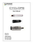
Precision Measurement Engineering, Inc. • www.Turner Designs.com
USB Cyclops-7 Logger User’s Manual
(Interchangeable and Fixed Sensors)
2015
Precision Measurement Engineering, Inc.
(760) 727-0300
www.Turner Designs.com
1
(INTENTIONALLY BLANK)
Precision Measurement Engineering, Inc.
(760) 727-0300
www.Turner Designs.com
2
Warranty
1-YEAR LIMITED WARRANTY
Precision Measurement Engineering, Inc. warrant that the Logger shall be free of
defects in workmanship and materials, under normal use, for a period of one year
from the date of shipment. This warranty is made only to the original purchaser. In the
event a Logger covered by this warranty fails to operate according to our published
specifications, then return it freight pre-paid to Precision Measurement Engineering or
an authorized Service Provider. Precision Measurement Engineering (PME) will
repair the unit at no charge to the customer and bear the cost of return shipment to
customer. Carefully pack all components, as the customer is responsible for any
freight damage.
This warranty does not apply to services or consumable / expendable items (such as
batteries, fuses and ropes) required for general maintenance. The Cyclops-7
sensor, manufactured by Turner Designs, is warranted only to the limit of the
warranties provided by their original manufacturer.
PME makes no warranty, either expressed or implied, that the sensors will be
operable after they are exposed to adverse environmental conditions, such as biofouling, oil fouling, freezing temperatures or others.
This warranty is void if, in our opinion, the Logger has been damaged by accident,
mishandled, altered, or repaired by the customer, where such treatment has affected
its performance or reliability. In the event of such treatment by the customer, costs for
repairs plus two-way freight costs (no COD shipments will be accepted) will be borne
by the customer. In such cases, an estimate will be submitted for approval before
repair work is started. Items found to be defective should be returned to PME
carefully packed, as the customer will be responsible for freight damage.
Incidental or consequential damages or costs incurred as a result of the product
malfunction are not the responsibility of PME.
For all warranty or non-warranty returns please obtain, complete, and submit a RMA
to PME. This RMA form may be obtained at
http://www.pme.com/HTML%20Docs/RMAform.html
After submission of this form, then PME will respond with a RMA number. Please
place this number on all shipments and related communications.
Precision Measurement Engineering, Inc.
(760) 727-0300
www.Turner Designs.com
3
Safety Information
BURSTING HAZARD
Should water enter the Cyclops-7 Logger and come into contact with the enclosed
batteries, then the batteries may generate gas causing the internal pressure to
increase. This gas will likely exit via the same location where the water entered, but
not necessarily. The Cyclops-7 Logger is designed to release internal pressure as
the end cap is unscrewed, prior to the disengagement of the end cap threads. If
internal pressure is suspected, then treat the Cyclops-7 Logger with extreme caution.
Revision History
Date
2015FEB24
2015APR16
2015APR28
2015MAY08
2015MAY25
2015JUN25
Revision Description
Copied from RS232 C7 manual
Added Android device instructions
Updated wording
Inserted pictures in Chapter 3
Released for distribution to customer
Added evaluation of calibration result
Precision Measurement Engineering, Inc.
(760) 727-0300
www.Turner Designs.com
4
CONTENTS
Chapter 1 Quick Start
1.1 Calibrate and Go
1.2 A Few Details
Chapter 2 Software
2.1
2.2
2.3
2.4
Overview and Software Installation
Cyc7Control
Cyc7Plot
Cyc7Concatenate
Chapter 3 Cyclops-7 Logger
3.1
3.2
3.3
3.4
3.5
Overview
Opening and Closing the Logger
Electrical Connections and Controls
Battery Replacement
Interchangeable Sensor Installation
Precision Measurement Engineering, Inc.
(760) 727-0300
www.Turner Designs.com
5
Chapter 1: Quick Start
1.1 Calibrate and Go
PME produces two types of loggers, a logger with the sensor permanently installed
and a logger with a connector that you will use to plug in your own sensor. Even if
the sensor is already installed, the logger/sensor are provided to you in an uncalibrated state. The logger itself is set to measure temperature and concentration
once every 10 minutes and record 1 file of measurements daily. However, you must
calibrate the sensor before the system can be used. At one measurement every 10
minutes the Cyclops-7 Logger will operate for roughly a half year before the internal
battery is expended.
At the end of the deployment period you need only to open the logger and connect it
to a host device via USB. The Cyclops-7 Logger will appear as a ‘thumb drive’. Your
temperature and sensor measurements, together with a time stamp indicating the
time the measurement was made, are recorded in text files in the folder having the
serial number of your Cyclops-7 Logger. These files can be copied onto any
Windows or Mac host computer.
This Manual and other software is supplied in files on the Cyclops-7 Logger:
•
•
•
Cyc7Control allows you to see the state of the logger as well as set the recording
interval.
Cyc7Plot allows you to see plots of the recorded measurements.
C7Concatenate gathers all the daily files into one CAT.txt file.
When not connected to USB, your Cyclops-7 Logger will record measurements if the
Recording Control Switch is in the Record position. If you wish to stop recording,
switch the Recording Control Switch to the Halt position.
You may switch the Recording Control Switch at any time.
Follow these steps to start the deployment, logging Cyclops-7 output and
Temperature once each 10 minutes:
1) Install your sensor onto the logger if required as described in Chapter 3.
2) Calibrate the sensor/logger as described in Chapter 2, Cyc7Control program.
3) Open the Cyclops-7 Logger (if not already open from calibration) as described in
Chapter 3.
4) Switch the Recording Control Switch to the Record position. The LED will flash
green 5 times. The Cyclops-7 Logger will now record a measurement of time,
Precision Measurement Engineering, Inc.
(760) 727-0300
www.Turner Designs.com
6
battery voltage, temperature, and sensor output every 10 minutes (or at some
other interval you may have set using Cyc7Control).
5) Inspect the o-ring seal for debris.
6) Close the Cyclops-7 Logger by screwing the white housing back onto the black
end cap.
7) Deploy the Cyclops-7 Logger.
Follow these steps to end the deployment
1)
2)
3)
4)
Recover the Cyclops-7 Logger
Clean and dry all accessible surfaces.
Open the Cyclops-7 as described in Chapter 3.
Connect to a Windows host computer via USB. The Cyclops-7 Logger will appear
as a ‘thumb drive’.
5) Copy the folder having the same serial number as the Cyclops-7 Logger (example
7377-191770) to the host computer.
6) (Suggested, but optional) Delete the measurement folder, but NOT Cyc7Control
or the other .jar programs or manual.
7) (Optionally) run the Cyc7Plot program to see a plot of measurements.
8) (Optionally) Run the C7Concatenate program to gather together all the daily files
of measurements into one CAT.txt file.
9) If no more recording is desired, switch the Recording Control Switch to Halt,
otherwise leave it set to Record to begin recording after USB disconnection.
10) Disconnect the Cyclops-7 Logger from the USB connection.
11) Inspect the o-ring seal for debris.
12) Close the Cyclops-7 Logger by screwing the white housing back onto the black
end cap.
Remove the batteries if storing the Cyclops-7 Logger for extended periods.
1.2 A Few Details
The previous section gives instructions for sampling at 10-minute intervals. However
there are a few additional details that will enhance use of the Cyclops-7 Logger.
Sensor guard – The sensor guard is the long tube having slots in the end that covers
the Turner C7 sensor. This guard not only protects the sensor but also establishes a
consistent field of view for the sensor. The guard must be used when the sensor is
calibrated and also when it is used for measurements in the field.
Sampling rate – The Cyclops-7 Logger records measurements at equal time
intervals. The default time interval is 10 minutes. However, it is also possible to
instruct the Cyclops-7 Logger to record at different intervals. This is accomplished by
connecting a Windows computer to the logger and using the Cyc7Control program
supplied for this purpose. Recording intervals must be 1 or more minutes and must
be less than or equal to 60 minutes. Intervals outside this range will be rejected by
Cyc7Control. (Contact PME for other recording intervals.)
Precision Measurement Engineering, Inc.
(760) 727-0300
www.Turner Designs.com
7
Please refer to Chapter 2 for instructions on operating the Cyc7Control program.
Time – All Cyclops-7 Logger times are UTC (formerly known as Greenwich mean
time (GMT)). The Cyclops-7 Logger internal clock will drift in the < 10 ppm range
(<about 30 secnds/month) so you should plan to connect it occasionally to a host
having an internet connection. The Cyc7Control program will automatically set time
based on an internet time server.
Please refer to Chapter 2 for instructions on operating the Cyc7Control program.
File Information – The Cyclops-7 Logger software creates 1 file daily on the
Cyclops-7 Logger’s internal SD card.. The number of measurements in each file will
depend upon the sample interval. Files are named by the time of the first
measurement within the file based on the logger’s internal clock and expressed in
YYYY-MM-DD HHMMSSZ.txt format. For example a file having the first
measurement on September 9, 2014 at 17:39:00 UTC will be named
2014-09-09 173900Z.txt
Files can be uploaded from the Cyclops-7 Logger by connecting the Logger to a host
computer and by using the host computer to copy/past the files from Logger to some
host computer storage.
Each measurement within files has a time stamp. The time stamp format is Unix
Epoch 1970, the number of seconds that have passed since the first moment of
1970. This may be inconvenient in some cases. If so, the C7Concatenate software
not only concatenates all the measurement files but also adds more readable
statements of the time stamp.
Please refer to Chapter 2 for instructions on operating the C7Concatenate program.
The Cyclops-7 Logger requires time and battery energy to work through the file
directory on SD card to allocate new file space. A few hundred files on SD is not a
problem, but as the number of files grows large into the thousands the Logger may
suffer decreased battery life or other performance problems. Please, at the earliest
convenient time, copy recorded files to a host computer and delete them from the
Logger. Also, do not use the Logger to store files unrelated to Logger operation.
Cleaning the Sensor – The sensor may be cleaned by unscrewing the black sensor
guard and gently wiping the optical face.
Battery Life – The Cyclops-7 Logger consumes battery power mostly from the
Cyclops-7 sensor, but also slightly from simply keeping track of time, writing files,
sleeping, and other activities. The Cyclops-7 Logger will record approximately
30,000 total samples and will operate for up to a year (depending on sample interval)
when powered by the battery pack (2 X alkaline ‘C’ cells) supplied by PME.
Precision Measurement Engineering, Inc.
(760) 727-0300
www.Turner Designs.com
8
Keep a general record of Cyclops-7 Logger number of samples. It is not possible to
accurately determine the charge state of the battery pack from measurements of its
terminal voltage. If you have a general idea of the number of samples already
obtained on a battery, then you can make a guess as to how many more samples
remain. Err on the side of caution.
The 2 X ‘C’ battery pack holds the batteries very tightly. The holder itself is glued to
the aluminum chassis. Take care when changing batteries that the glue joint is not
broken. Always use the paper tube supplied with the Cyclops-7 to contain the
batteries. Use only new batteries as replacements.
Coin Cell Battery Life – The Cyclops-7 Logger uses a coin cell for backup of the
clock when the power is switched off. This coin cell will supply roughly 2 years of
clock operation, but this is only required if the main power is off. Should the coin cell
discharge it must be replaced. Coin cells are not user-replaceable.
O-Ring and Seal – When the cover is screwed on, it passes along the o-ring located
in the end cap several revolutions. Keep this o-ring lightly lubricated with silicone
grease or oil compatible with buna-N o-ring material.
When the Cyclops-7 Logger is opened after deployment, a small number of water
drops are deposited on the inner surface of the o-ring. When the pressure housing is
screwed back on, these drops become trapped inside the Cyclops-7 Logger. Be sure
to carefully dry the o-ring and adjacent surfaces (especially underneath) prior to
closing the Cyclops-7. Re-lube the o-ring at this time. Remove any debris from the
drying process.
Closing the Logger – The logger is much more difficult to open than to close. Screw
the white logger housing onto the black cap until the housing touches the cap. No
further tightening is necessary.
LED Indications – The Cyclops-7 Logger performs various tests as it begins logging
operations. If any test fails the software flashes the LED light and re-conducts the
test. In general if a test fails once it will continue to fail and the LED light will
continue to flash. The following table gives the number of flashes and the reason
these flashes appear.
Precision Measurement Engineering, Inc.
(760) 727-0300
www.Turner Designs.com
9
LED
1 Green
Flash
1 Green
Flash
5 Green
Flashes
5 Red
Flashes
Continuously
Green
Continuously
Flashing Red
Reason
Normal. Presented immediately after new batteries are
installed. Indicates that the CPU has started its program.
Occurs at the time of sampling for sample intervals of 1 minute
or less.
Normal. Indicates that miniDOT is beginning to record
measurements. This indication appears in response to
switching the Recording Control Switch to Record.
Normal. Indicates the miniDOT is ending recording of
measurements. This indication appears in response to
switching the Recording Control Switch to Halt.
Normal. Indicates the miniDOT is connected to a host device
via USB.
SD card write error. Try removing/reinstalling batteries.
Contact PME.
AutoRanging – The Cyclops-7 sensor has three output ranges: 1X, 10X and 100X.
The best of these ranges is automatically selected by the logger based on the voltage
measured of the sensor. The logger software remembers the best range and, at
each sample time, first measures sensor output voltage using this range. Software
then reviews this voltage to determine if the range was appropriate. In most cases
the range will be appropriate and the measurement is recorded. However sometimes
software determines that a different range would yield a better measurement. In this
case software selects a new “best range” and re-measures the sensor output voltage
using this range. This new best range becomes the range selected at the next
sample time. The best range is determined as follows:
Sensor Voltage
0.00 to 0.04
0.04 to 0.4
0.4 and higher
Best Range
100X
10X
1X
Should the first voltage measurement be unacceptably close to the sensor maximum
output voltage (an over-range condition) the first voltage is re-measured using range
of 1X and the best range calculated. This range becomes the best range and
software proceeds as above.
Calculation of Engineering Units – Engineering units are calculated from voltage
measurements of the sensor and from information gained during calibration (see
Chapter 4). The result of calibration is the following information:
Name
Vz1
Vz10
Definition
Voltage output of sensor in zero solution on
range 1X
Voltage output of sensor in zero solution on
range 10X
Precision Measurement Engineering, Inc.
(760) 727-0300
www.Turner Designs.com
10
Vz100
S
Voltage output of sensor in zero solution on
range 100X
Sensitivity of sensor
Vz1, Vz10, and Vz100 are measured with the sensor in a solution of zero
concentration. S is determined from the voltage output of the sensor using the “best
range”, described above, with the sensor in a reference solution of known
concentration. The user must enter the concentration value of this solution, given the
name C. The sensor voltage is measured in this solution and given the name Vs.
The following table shows how S is determined.
Range
1X
10X
100X
S
S = C / (Vs – Vz1)
S = 10.0 * C / (Vs – Vz10)
S = 100 * C / (Vs – Vz100)
Note that since only one calibration concentration is actually measured, there is only
one S determined. However this S is used to compute engineering units from the
other ranges should these be implemented by the logger during the measurement of
samples.
Engineering units are computed as shown in the following table:
Range
1X
10X
100X
EU
EU = S * (Vs – Vz1)
EU = S * (Vs– Vz10) / 10.0
EU = S * (Vs– Vz100) / 100.0
Engineering units computed using the same range that was used to determine S will
be more accurate than engineering units computed using other ranges since the
sensor may not exactly implement ranges. For example the 100X range may
actually be implemented by circuitry as 100.1X but the calculations would use 100X.
Closing and Opening – Close and open Cyclops-7 Logger like you would a
flashlight: open by unscrewing the white cylinder from the black end cap. Close by
screwing the white cylinder on. When closing, do not tighten the white cylinder. Just
screw it on until it makes contact with the black end cap. See Chapter 3 for more
instructions.
Storage When Not in Use – Remove the batteries.
Java – miniDOT programs depend on Java and require Java 1.7 or higher. Update
Java at
https://java.com/en/download/index.jsp
Precision Measurement Engineering, Inc.
(760) 727-0300
www.Turner Designs.com
11
Upload Files to an Android device – It is possible to transfer your measurement
files from your logger to an android device. This operation has 3 prerequisites.
1. An Android device equipped with USB On-The-Go (OTG). OTG is a feature on
most modern Android devices that allows them to act as a USB host. OTG was
introduced with Android version 3.1 and should be a useable feature on most
devices. It is still possible that your device doesn't support OTG. Please test your
device with a logger prior to attempting to upload while in the field.
2. A USB OTG cable. This is essentially an adapter with a micro USB connector on
one end that connects to your Android device and a standard A type USB plug on
the other. The cable supplied with the logger connects to this end.
3. A "File Explorer" app downloaded on your Android device. These types of apps
assist with being able to view and move files from device to device. "ES File
Explorer" is a free app available on the Google app store and is recommended for
use with the logger.
If the 3 requirements are met, then connect the logger to your device. You should
see the logger green connection light come on and your device display a message
about "preparing USB storage". When "USB storage ready" is shown, use your "file
explorer" program to move your data from the logger onto you device.
Again, it is highly recommended that you try this operation at your work station prior
to depending upon this in the field.
Currently the associated logger programs, Control, Plot, and Concatenate, are not
supported by Android devices.
Precision Measurement Engineering, Inc.
(760) 727-0300
www.Turner Designs.com
12
Chapter 2: Software
2.1 Overview and Software Installation
The miniDOT arrives with these files:
•
•
•
•
Cyc7Control.jar allows you to see the state of the logger as well as set the
recording interval.
Cyc7Plot.jar allows you to see plots of the recorded measurements.
C7Concatenate.jar gathers all the daily files into one CAT.txt file.
Manual.pdf this manual.
These files are located on the root directory of the Cyclops-7 Logger.
PME suggests you leave these programs where they are on the Logger, but you may
copy them to any folder on your computer’s hard drive.
Cyc7Control, Cyc7Plot, and C7Concatenate are Java language programs that require
the host computer to have the Java Runtime Engine V1.7 (JRE) or later installed.
This engine is commonly required for internet applications and will likely already be
installed on the host computer. You can test this by running Cyc7Plot. If this
program displays its graphical user interface then the JRE is installed. If not then the
JRE can be downloaded via internet from
http://www.java.com/en/download/windows_xpi.jsp
At this time Cyclops-7 Logger software is supported on Windows operating systems,
but may also operate on Macintosh and perhaps Linux.
2.1 Cyc7Control
The Cyc7Control program provides these services:
•
•
•
It enables time setting (based on internet timeserver clock).
It enables sample interval setting.
It enables calibration of the sensor.
Turner C7 sensors, are not factory calibrated. Calibration must be physically
performed by the customer. Calibration consists of an experiment where the sensor
is exposed to two solutions, the first having 0 concentration of the sensed material
(chl-a, rhodamineQ whatever the C7 sensor senses) and a second solution having a
known concentration created by the customer. Cyc7Control software records sensor
output in each solution and creates a linear fit to these two points. After calibration
the Cyclops 7 Logger will measure sensor output and record it in engineering units
using this linear fit.
Precision Measurement Engineering, Inc.
(760) 727-0300
www.Turner Designs.com
13
Begin program operation by clicking on Cyc7Control.jar. Software presents the
screen shown below:
The Cyclops-7 Logger must be connected to USB at this time. When correctly
connected the Logger will display a constant green light.
Precision Measurement Engineering, Inc.
(760) 727-0300
www.Turner Designs.com
14
Click the Connect button. The software will contact the logger. If the connection is
successful the button will turn green and display “Connected”. The Serial Number
and other parameters will be filled in from information take from the Logger.
If the host computer is connected to the internet, the current difference between an
internet time server’s time and the Logger internal clock will be displayed. And, if
more than a week has passed since time was last set, the Logger clock will be set
and check mark icon will appear. If the host computer is not connected to the internet
no time services will occur.
The current Logger sample interval will be displayed next to the Set Sample Interval
button. If this interval is acceptable the interval need not be set.
To set the interval, enter a interval not less than 1 minute and not greater than 60
minutes. Click the Set Sample Interval button. Shorter and faster intervals are
available. Contact PME.
Turner C7 sensors are optical devices that operate by sending colored light into the
water and observing how much light returns. The field of view available to these
sensors is quite important in establishing their response. PME’s Cyclops 7 Logger is
supplied with a sensor cover that not only protects the sensor from damage but also
establishes the field of view. This cover has slots near where it covers the sensor so
that exterior water can enter and be sensed.
The sensor cover must be in position when the sensor is calibrated and must be in
the same position when the sensor is used.
A small amount of light can exit through the sensor cover slots, be reflected by the
container holding the calibration solution, and return. Calibrate the sensor in black
containers.
Exterior light such as room lighting or sunlight can enter through the slots and cause
a very small measurement effect. Attempt to calibrate in the same lighting as the
system will experience in field use.
Be sure that there are no bubbles trapped in the cover or stuck on the sensor.
Calibration proceeds by dipping the system in one solution and then the next. Take
care not to transport one solution to the next. Mix two 0 solutions and two solutions
of the sensed material. Label one each as the “calibration” and one each as the
“wash” When moving the sensor back and forth first dip the sensor in the wash then
into the calibration. The most noticeable effect is when the 0 solution is contaminated
prior to calibration. If the 0 solution is contaminated and is actually 1, and if this is not
noticed and the value 0 is entered into Cyc7Control, then later in a truly 0 solution the
Cyclops 7 Logger will be indicated as a concentration of –1. A negative
concentration can not exist and so the sensor is suspected of poor measurement
when the problem is that it was poorly calibrated.
Precision Measurement Engineering, Inc.
(760) 727-0300
www.Turner Designs.com
15
Cyc7Control requires that the host computer be connected to the Cyclops 7 Logger at
the time the calibration is performed. The logger must be open at this time. Take
care that no calibrating solutions splash onto logger circuits.
When calibration is completed, use the sensor to log measurements in each
calibration solution. Do this right away using the same solutions that were used for
calibration. The values 0 and the known concentration should be recorded by the
logger. This gives a check on the results of calibration.
Cyclops-7 Loggers support various Turner Cyclops-7 sensors. The sensor type is
shown on a small tag inside the logger.
Sensors are calibrated in response to the Calibrate button, after both the Unit of
Measure and the Calibration Value are entered.
Enter the unit of measure that is appropriate for the Cyclops 7 sensor mounted on the
logger.
Enter the calibration value for the solution.
Click on the Calibrate button. The adjacent scroll bar shows how far the program has
progress through the calibration procedure.
Precision Measurement Engineering, Inc.
(760) 727-0300
www.Turner Designs.com
16
A dialog window appears instructing you to place the sensor in the zero solution.
This will most likely simply be clear water contained in a bucket. Whatever the
solution, the sensor after calibration will report 0 when returned to this solution. Click
OK when the sensor is suitably positioned. If this solution is NOT 0 and the sensor is
later placed into a solution that IS 0 the sensor will report a negative concentration!
Negative concentration values can also result if the reflected light in a later solution is
less.
Precision Measurement Engineering, Inc.
(760) 727-0300
www.Turner Designs.com
17
At this time the software reads information from the sensor, selecting all three ranges
of the sensor sensitivity.
When this is completed a Zeroing of sensor completed dialog appears. Click OK.
Precision Measurement Engineering, Inc.
(760) 727-0300
www.Turner Designs.com
18
A “Please place sensor in calibration standard of <Calibration Value> (<Unit of
Measure>)” dialog appears. In the screen shot above the value of 400 (ppb) is
displayed. This information is taken from the Unit of Measure and Calibration Value
text boxes and will be whatever is entered in the boxes.
Place the sensor in the calibration solution. Whatever the solution, the sensor after
calibration will report the calibration value (400 ppb in the above example) when
Precision Measurement Engineering, Inc.
(760) 727-0300
www.Turner Designs.com
19
returned to this solution. The same considerations about solution accuracy and
reflected light apply in a similar way to those a zeroing.
Click OK. At this time the software reads information from the sensor, selecting the
best sensitivity range.
When this is completed a “Calibration completed” dialog window appears along with
the actual calibration results.
Precision Measurement Engineering, Inc.
(760) 727-0300
www.Turner Designs.com
20
Notice that calibration information is displayed in the bottom window. Also, this
information is automatically transmitted to the Cyclops-7 Logger. The Logger is now
calibrated.
Click OK. At this time the calibration is saved on the Cyclops-7 Logger SD card.
Note that the calibration has been installed in the sensor and the sensor is calibrated
no matter if the results are saved on disk or not.
Precision Measurement Engineering, Inc.
(760) 727-0300
www.Turner Designs.com
21
A dialog window appears indicating the location where the calibration has been
saved. You may later use the host computer’s file copy/paste to move this file to
some host computer location. You may choose to leave the file on Logger SD or
delete it.
You may read the saved file later using a text file editor. The file will be similar to this
file except that “test” will be replaced with the unit of measure selected for calibration.
Precision Measurement Engineering, Inc.
(760) 727-0300
www.Turner Designs.com
22
================================================
Turner Cyclops 7 Logger Calibration
Date: Oct 17, 2014 14:54:13
S/N: 18 Battery: 3.103 (V)
Unit of Measure: test
================================================
Gain = 1, Sensor Output in Zero Solution, Vz1: 0.015335 (Volts)
Gain = 10, Sensor Output in Zero Solution, Vz10: 0.018888 (Volts)
Gain = 100, Sensor Output in Zero Solution, Vz100: 0.066867 (Volts)
Gain = 1, Sensor Output in 100.0(test) Solution: 1.22355 (Volts)
Gain = 1 Sensor Sensitivity (Measured at Gain = 1): 82.76672612076494 (test/Volt)
A note about judging your calibration result: The table below presents typical values
that result from calibration.
Sensor
Solution
Rhodamine
(1)
Phycocanin
(2)
PTSA
(3)
Optical
Brighteners
CDOM
(3)
(3)
Crude Oil
(3)
Turbidity
(4)
Fluorescein
(5)
Phycoerythrin
(6)
in vivo
Chlorophyll
(7)
(1)
(2)
(3)
(4)
(5)
(6)
(7)
Vz1
(Volt)
0 to
0.035
0 to
0.035
0 to
0.035
0 to
0.035
0 to
0.035
0 to
0.035
0 to
0.035
0 to
0.035
0 to
0.035
0 to
0.035
Vz10
(Volt)
0 to 0.075
Vz100
(Volt)
5 to 0.150
Sensitivity
(Unit)
200
Unit
0 to 0.075
5 to 0.150
8000
ppb/Volt
0 to 0.200
0 to 0.500
130
ppb/Volt
0 to 0.200
0 to 0.500
3000
ppb/Volt
0 to 0.200
0 to 0.500
1000
ppb/Volt
0 to 0.200
0 to 0.500
540
ppb/Volt
0 to 0.075
0.005 to
0.150
0.005 to
0.150
0 to 0.500
600
NTU/Volt
100
ppb/Volt
150
ppb/Volt
100
ug/l
0 to 0.075
0 to 0.075
0 to 0.075
0.005 to
0.200
ppb/Volt
Rhodamine dye diluted in deionized water.
Specific species pigment diluted in deionized water
PTSA (1, 3, 6, 8 - Pyrenetetrasulfonic Acid Tetrasodium Salt) calibration standard
Amco Clear Turbidity Standard Solutions
Fluorescein dye diluted in artificial sea water.
Phycoerythrin pigment diluted in Deionized water
algal monoculture consisting of the species Skeletonena costatum.
Sensor calibrations should always show Vz1..Vz100 in the ranges given. The
sensitivity can vary but variations larger than +/- 20% should be suspect.
Also note that sensors can only produce as much as 5 Volts at their lowest sensitivity.
Therefore your reference solutions have a maximum concentration that can be
sensed. For example Rhodamine typical sensitivity is 200 ppb/Volt so only a
Precision Measurement Engineering, Inc.
(760) 727-0300
www.Turner Designs.com
23
maximum of 1000 ppb can be sensed. The “Sensor Output in xxx Solution” will
always be less than 5.0 Volts since this is all the sensor can produce but should be
less than 4.0 Volts.
A note about Turner solid state secondary standards: These standards are not
supplied with any calibration value, so they are not at first useful for calibration.
However, once the sensor is calibrated the solid state secondary standard can be
placed onto the sensor and adjusted so that the sensed value is some arbitrary value.
Please refer to Turner’s documentation concerning the Solid Secondary Standard
that is supplied with the standard or via the internet:
http://www.turnerdesigns.com/t2/doc/instructions/998-6800.pdf
Install the standard as described. The logger’s sensor guard must be unscrewed and
removed for this procedure.
Operationally, adjustment of a standard is not well implemented in the logger
software. Step 2 of the Use of the Solid Secondary Standard for in vivo Chlorophyll
Applications on page 1 of this document assumes that the sensor output can be
viewed in real time. However this output can only be logged by the Cyclops-7
Logger. A short recording of the measurement must be made, and then the record
reviewed, to determine the sensed value. The process must be repeated by trials to
adjust the standard as described in the document.
A note on chlorophyll calibration: Please review the Turner Designs document titled
“In Vivo Chlorophyll: Concepts & Concerns”. PME sometimes provides this
document together with this Manual or it can be found at Turner’s Application Notes
http://www.turnerdesigns.com/customer-care/fluorometer-application-notes/chlorophyll-fluorometer-applicationnotes
2.2 Cyc7Plot
The Cyc7Plot program provides the service of plotting Cyclops-7 Logger files.
Begin program operation by clicking on C7Plot.jar. Software presents the screen
shown below.
Precision Measurement Engineering, Inc.
(760) 727-0300
www.Turner Designs.com
24
C7Plot plots the files recorded by the Cyclops-7 Logger. The software reads all
Logger files in a folder, except the CAT.txt file.
Notice that the software has automatically suggested the Cyclops-7 Logger SD card
as the Data Folder. You may accept this or click Select DATA Folder to find some
other source for the plot.
DATA folders MUST NOT contain any other files besides files written by the Cyclops7 Logger. This folder can be on the SD card from the Cyclops-7 or it can be from a
copy of this on your computer’s hard drive.
A few thousand measurements can be plotted directly from Cyclops-7 Logger SD.
However it is best to copy large measurement sets to the host computer and select
them there since file access to the Logger is slow.
Press ‘Plot’ to begin measurement processing. The software reads all Cyclops-7
Logger data files in the Data presents a plot of the measurements similar to the plot
shown below.
Precision Measurement Engineering, Inc.
(760) 727-0300
www.Turner Designs.com
25
You may zoom this plot by drawing a square from upper left to lower right (click and
hold left mouse button) that defines the zoom region. To zoom completely out,
attempt to draw a square from lower right to upper left. The mouse will scroll the
image if the CTRL key is held down. Right click on the plot for options such as copy
and print.
The software may be run multiple times at the same time (select Data Folder, press
Process, select new Data Folder, press Process...). In this case it produces multiple
plots. Presently the plots are presented exactly on top of each other and so when a
new plot appears it is not obvious that the old plot is still there. It is. Just move the
new plot to see it. Closing any plot closes all.
End C7Plot by closing any window.
The software can be re-run at any time. If an already processed DATA Folder is
selected the software simply reads the measurement files again.
Special note: plotting of sample sets of more than 200K samples may consume all
memory available to the host computer’s Java. C7Plot will present a partial plot and
freeze in this case. A simple solution is to separate the files into multiple folders and
plot each folder individually.
Precision Measurement Engineering, Inc.
(760) 727-0300
www.Turner Designs.com
26
2.3 Cyc7Concatenate
The Cyc7Concatenate program provides these services:
•
•
•
It gathers together all Cyclops-7 Logger files in the DATA folder in time sequence.
It translates the Logger time stamp into two additional formats.
It writes all times and measurements into a single CAT.txt file in the DATA Folder.
Begin program operation by clicking on Cyc7Concatenate.jar. Software presents the
screen shown below.
Cyc7Concatenate concatenates the files recorded by the Cyclops-7 Logger. The
software reads all Logger files in a folder, except the CAT.txt file. Software
translates Logger time stamps into two additional formats, and saves the result in a
CAT.txt file in the DATA Folder.
Notice that the software has automatically suggested the Cyclops-7 Logger SD card
as the Data Folder. You may accept this or click Select DATA Folder to find some
other source for the plot.
DATA folders MUST NOT contain any other files besides files written by the Cyclops7 Logger. This folder can be on the SD card from the Cyclops-7 or it can be from a
copy of this on your computer’s hard drive.
A few thousand measurements can be concatenated directly from Cyclops-7 Logger
SD. However it is best to copy large measurement sets to the host computer and
select them there since file access to the Logger is slow.
Press ‘Concatenate’ to begin measurement processing. The software reads all
Cyclops-7 Logger data files in the DATA Folder. These are written to the same
folder. Software presents a dialog window when the process is completed.
Precision Measurement Engineering, Inc.
(760) 727-0300
www.Turner Designs.com
27
Click OK. The Cyc7Concatenate software can be re-run at any time.
End Cyc7Concatenate operation by closing the window.
The CAT.txt file will resemble the following:
Precision Measurement Engineering, Inc.
(760) 727-0300
www.Turner Designs.com
28
Chapter 3: Cyclops-7 Logger
3.1 Overview
All of the Cyclops-7 Logger measurements pass from the sensors onto the SD card it
contains. Files are transferred to a host computer via USB connection where the
Cyclops-7 Logger appears as a “thumb drive”. Measurements may be plotted by
Cyc7Plot and files concatenated by Cyc7Concatenate. The Cyclops-7 Logger itself is
controlled and calibrated by Cyc7Control. Customers are required to open the logger
each time measurements are transferred to the host computer. This chapter
describes the logger internal features.
3.2 Opening and Closing the Logger
The logger circuitry is contained in a waterproof housing that must be opened. The
housing is opened by unscrewing the white pressure housing from the black end cap.
Turn the pressure housing counter clockwise relative to black end cap. Close by
reversing this procedure after being sure that the o-ring is free from debris. Lube oring occasionally with grease intended for buna-n o-ring material.
Precision Measurement Engineering, Inc.
(760) 727-0300
www.Turner Designs.com
29
The logger is much more difficult to open than to close. Screw the white logger
housing onto the black cap until the housing touches the cap. No further tightening is
necessary.
Please attempt to handle the Cyc7Logger only by the aluminum chassis, without
touching the circuit card.
When closing the Cyclops-7 Logger inspect the o-ring and interior of the white
cylinder for debris, lube the o-ring, and screw the white cylinder onto the black end
cap until the cylinder just touches the end cap. Do not Tighten! The Cyclops-7
Logger tends to get a little tighter during deployment.
If you can not open the Cyclops-7 Logger by yourself, find another person with strong
hands. This person should grip the black end cap while you turn the white cylinder.
3.3 Electrical Connections and Controls
Removal of the cover reveals the logger connections and controls, shown below.
The LED Light is a LED that can display either red or green light. This is used to
indicate different features described in Chapter 1 in this manual.
Precision Measurement Engineering, Inc.
(760) 727-0300
www.Turner Designs.com
30
The Logger Control Switch controls the logger mode:
•
•
Record – When the switch is in this position the logger is recording
measurements.
Halt – When the switch is in this position the logger is not recording and is
sleeping at low power.
The USB Connection allows communication between the logger and an external
host computer. When connected, the logger is in halt mode regardless of the Logger
Control Switch position. When disconnected the logger mode is controlled by the
switch position. The switch position may be changed while the USB is connected.
The Main Batteries (2 X “C” at right of picture above) provide main power to the
Cyclops-7 Logger. Note the positive (+) terminal.
3.4 Battery Replacement
Carefully remove both “C” cells, noting the direction of the (+) terminals. These both
are oriented towards the Logger circuit. Insert new ‘C’ cells into the paper tube and
re-install the pair into the battery holder. Take care not to break the glue connection
between the holder and the aluminum chassis.
3.5 Interchangeable Sensor Installation
PME provides two types of Cyclops-7 loggers. One type has the sensor permanently
mounted by PME. This section describes the other type where the sensor is plugged
to the logger. The other features described throughout this document are the same
for both types of loggers.
Arrange the parts as shown in the picture below
Precision Measurement Engineering, Inc.
(760) 727-0300
www.Turner Designs.com
31
The small circular black clip shown to the right of the C7 sensor will be found installed
on the logger connector. This can be removed by unscrewing it from the connector,
and then gently prying open the ‘C’ clip center piece.
Screw one side of the clip fully on to the sensor. Screw the opposite side fully onto
the connector as shown in the picture below.
Precision Measurement Engineering, Inc.
(760) 727-0300
www.Turner Designs.com
32
Be sure both are fully screwed on. If either is not, the clip will hold the sensor in a
position where it may not make full contact with the connector.
Plug the senor fully into the connector as shown in the picture below.
Precision Measurement Engineering, Inc.
(760) 727-0300
www.Turner Designs.com
33
The clip faces will mate. Note that if the clip is not fully screwed onto the connector it
will still appear as shown in the picture above, but the sensor may not be making
complete reliable contact with the logger.
Snap the remaining clip part onto the clip to secure the sensor to clip connection.
Precision Measurement Engineering, Inc.
(760) 727-0300
www.Turner Designs.com
34
Slide the sensor support (middle-right in first picture) over the sensor. Note this part
has an internal o-ring that comes against the sensor. This is not a water-proof seal.
It’s purpose is to firmly secure the sensor within the support. Next screw the sensor
guard (middle left in first picture) onto the sensor support. The completed assembly
is shown in the picture below.
Precision Measurement Engineering, Inc.
(760) 727-0300
www.Turner Designs.com
35
When exchanging the sensor, reverse the process steps given above.
The sensor connector is itself threaded into the logger end cap. This connector is
tightened, but since the logger end cap is plastic there is a limit to how tightened this
connector can be made. If the connector unscrews water can enter the logger and
cause permanent damage. Be observant when installing sensors. When installed,
the sensor should not be able to be rotated. Take care not to unscrew the sensor
and watch the sensor when unscrewing the sensor support since the o-ring will apply
a sight loosing rotation to the sensor. Should the sensor/connector become loose
discontinue use of the logger and contact PME.
Precision Measurement Engineering, Inc.
(760) 727-0300
www.Turner Designs.com
36