1
3.5.
Pedestrian Direction mode (no loop)
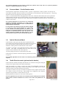
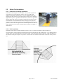
In this mode the controller attempts to analyse the direction of a bicycle or person traversing the switch pad and provide
an output, based on the direction determined.
If the passage of a wheel (bicycle) is sensed, the switch pad immediately activates the appropriate direction output.
Such output remains constant while the pressure of the wheel remains
on the sensor.
Where a wheel presence is not detected the controller assumes the
actuation is due to pedestrian movements on the switch pad. In this
case the direction can only be determined when the pedestrian moves
off the switch pad. At this time a brief output pulse is provided on the
appropriate direction output once the sensor is completely de-activated.
The delay feature can be used in this mode to provide an override
output if an actuation persists for the delay period without direction
being determined. In this case the signal is provided on both direction
outputs.
Note that further outputs will only occur once the switch-pad has been completely vacated between events.
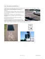
The intended application for this mode is without the optional vehicle loop and is for “passive pedestrian
detection” at signalised pedestrian crossings. Directional outputs are provided to signal the intended direction
of bicycles and pedestrians arriving at the sensor.
4.
Operating Instructions
4.1.
Switch Setting Selections
The faceplate switch settings allow the configuration of the operating mode of the controller, the time delay settings for
the tactile outputs and the inductive loop settings when the optional detection loop coil is imbedded in the sensor.
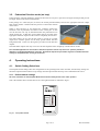
4.1.1. Default switch settings
All of the 8 switches on the faceplate Mode switch should initially be set to the “OFF” position.
This is the situation where all switches are set to the right-hand side as indicated in Fig 4.1.
Fig 4.1. Faceplate Details
Page 5 of 12
Rev 03 Controller