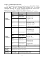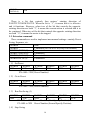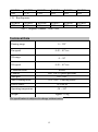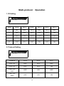
1
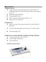
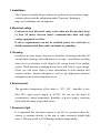
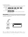
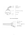
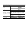
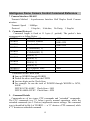
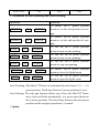
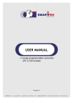
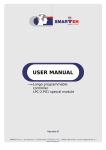
Dome2-P/T
Dome2HR-P/T HIGH RESOLUTION
User’s Manual
Before attempting to connect or operate this product, please read these
instructions completely
Main Features
1 Built-in receiver
l
l
l
Complete digital control with integrated CPU and SD RAM. All
configurable options stored in non-volatile memory to protect against
power cuts.
Integration and high durability.
16 programmable presets.
l
l
RS485 communication data, dome address 0-511.
Support Auto tour and pattern.
2 Pan/tilt drive
l Innovative design of the structure minimizes the outline shape and
dimensions.
l
A precision drive positioning system ensures a 0~355°pan rotation.
l
Tilt rotation range 0-90°.
3 Built-in color camera with high sensitivity and high resolution
l 3.6 mm lens fitted, other sizes available
l Auto back light compensation
l Auto white balance
Optional keyboard control
2
Preface
The 5” mini dome is an integration of the cutting-edge technique, most
developed manufacturing process and years of full experience in the industry.
Equipped with high-resolution camera and digital decoder, it represents the
trend of the new edition of surveillance product. Being
complete-digital-controlled and flexile programmable, it performs an excellent
fast-location and continuous object tracing. The simple and compact structure
ensures high reliability and long term running.
Super features lead a wide variety of use in large area surveying and moving
object tracing. For instance, integration building and banks securing, traffic
supervising, power stations watching, airports and stations monitoring. The
protocol is open and the dome is compatible with the host of systems.
This manual introduces dome functions and operations. Please read this manual
carefully prior to installation and operation.
Precautions
1 Transportation
Domes are sophisticated products and as such should be protected against
extremes of pressure, temperature, vibration and humidity during storage
and transportation.
2 Do not disassemble the Dome module
There are no user serviceable parts or settings inside. Failure to observe
this instruction could result in damage to the product and loss of warranty.
Only suitably qualified and authorized personnel may undertake repairs.
3
3 Installation
This Camera is suitable for use indoors or outdoors however before using
outdoors please read the information under "Exposure" heading at:
http://www.allthings.com.au/Appnotes
4 Electrical safety
Conform to local Electrical safety codes when use this product, keep
at least 50 meter between dome, communication data and high
voltage equipment or cables.
If above requirements can not be satisfied, please use steel tube to
shield communication Data cable, and make it grounding.
5 Cleaning
In order to get clear image, down cover should be cleaned periodically. Be
careful when cleaning, only hold down cover edge , avoid direct touching
down cover, acid matter in the fingers will corrupt down Cover plating
surface. Hard material scratching down cover will lead to vague image.
Please use soft clean cloth or other substitution to clean interior and
exterior surface. Neutral detergent as well as any high-grade furniture
detergent can be used to clean down cover.
6 Environment
The operation temperature of the dome is -30? ~50? , humidity is less
than 90%, input power supply is AC24V. Do not use the dome in
circumstances where temperature, humidity or power supply variations
fall outside the range of specified values.
7 Excessive light
It is important that the dome camera is not left in a position where the
camera is pointing directly at the sun or other extremely bright light
source. This may result in CCD damage and poor image quality.
4
Functions and Operations
These operating instructions cover the basic operation of the dome and its
features. When the dome is used with other manufacturers control system,
please regard the system controller instruction as standard. In the event of
special requirements outside the scope of this document it is advisable to
contact your local distributor.
1. Setting the dome ID
Setting dome ID by the DIP Switch of the dome, refer to the dome setting
for the details.(P.6)
2. Set up and call preset
Preset function is that dome stores current horizontal angle and title angle of
pan/Tilt, and position parameters into the memorizer. When necessary
dome calls these parameters and adjusts Pan/Tilt and camera to that position.
Operator can store and call presets easily and promptly by using controller,
the dome supports up to 64 presets.
l
To set a preset position
l
To call a preset position Call +
preset +
N +
N +
ENTER
ENTER
3. Auto Cruise
The preset positions can be programmed to be re-called in a set of sequence.
This sequence can be set to automatically cycle from one position to the
next at a setting time. This feature is called Auto cruise.
l Cruise sequence can be programmed from 1~16 presets.
l Start Auto cruise : SHOT + 1 + ENTER
l Stop Auto cruise by moving the joystick.
5
4. Auto Pan function
The auto pan function allows you to have the camera move back and forth
automatically, at a preset speed between the 2 preset camera positions.
l START : AUTO + N1 + ON + N2 + OFF
N1 stands for the position you want to start
N2 stands for the position you want to stop
l
STOP :
AUTO + OFF
or Move joystick, the dome will be controlled by manual and
the auto pan will stop.
Dome Setting
According to the different controlling system, confirm the used controlling
system before operation setting
OFF
1 2 3 4 5 6 7 8 9 10
ON
ID10 is for RS485 120O impedance. When control distance is far or
environment interference is severe, the ID10 should be set “ON”, when the
6
system connects many domes, ID10 of the farest dome from controller should
be set “ON”, other domes are set “OFF”.
Address
Switch
Switch
Switch
Switch
Switch
Switch
Switch
Switch
Switch
9
8
7
6
5
4
3
2
1
1
OFF
OFF
OFF
OFF
OFF
OFF
OFF
OFF
ON
2
OFF
OFF
OFF
OFF
OFF
OFF
OFF
ON
OFF
3
OFF
OFF
OFF
OFF
OFF
OFF
OFF
ON
ON
4
OFF
OFF
OFF
OFF
OFF
OFF
ON
OFF
OFF
5
OFF
OFF
OFF
OFF
OFF
OFF
ON
OFF
ON
6
OFF
OFF
OFF
OFF
OFF
OFF
ON
ON
OFF
7
OFF
OFF
OFF
OFF
OFF
OFF
ON
ON
ON
8
OFF
OFF
OFF
OFF
OFF
ON
OFF
OFF
OFF
9
OFF
OFF
OFF
OFF
OFF
ON
OFF
OFF
ON
10
OFF
OFF
OFF
OFF
OFF
ON
OFF
ON
OFF
11
OFF
OFF
OFF
OFF
OFF
ON
OFF
ON
ON
12
OFF
OFF
OFF
OFF
OFF
ON
ON
OFF
OFF
13
OFF
OFF
OFF
OFF
OFF
ON
ON
OFF
ON
14
OFF
OFF
OFF
OFF
OFF
ON
ON
ON
OFF
15
OFF
OFF
OFF
OFF
OFF
ON
ON
ON
ON
16
OFF
OFF
OFF
OFF
ON
OFF
OFF
OFF
OFF
17
OFF
OFF
OFF
OFF
ON
OFF
OFF
OFF
ON
18
OFF
OFF
OFF
OFF
ON
OFF
OFF
ON
OFF
19
OFF
OFF
OFF
OFF
ON
OFF
OFF
ON
ON
20
OFF
OFF
OFF
OFF
ON
OFF
ON
OFF
OFF
…
…
…
…
…
…
…
…
…
510
ON
ON
ON
ON
ON
ON
ON
ON
OFF
511
ON
ON
ON
ON
ON
ON
ON
ON
ON
When there is more than one dome adopted in the system, connect the
controlling cable in parallel, set the dome address by setting ID Switcher,
control the domes connected with one keyboard controller. Refer to the
controlling system manual for the detailed connection and operation.
7
Installation
Prior to installation and use of this product, the following warnings should be
observed:
1. Installation and servicing should only be done by qualified service
personnel or system installation personnel and conform to all local
codes.
2. When unpacking dome package, Pan/Tilt module should be handled
with care, not use hard thing to hit camera and other parts to avoid
unnecessary trouble.
3. Domes installation position must be away from high voltage as far as
possible.
4. Setting the dome address, controlling mode and protocol appropriately
before installation.
Wall Bracket (Optional)
8
1 AC24V
2 BNC Video output
3 RS485 data
Alum4 Aluminum Die Cast Housing
5 Acylic dome
6 Camera
Dome Connection Diagram
Brown L
AC24V
Blue N
Blue RS485A+
RS485 data
Yellow RS485BBNC Video output
9
Dome Structure Diagram
1. Connection Instruction
1) Video output connects to matrix or monitor
2) RS485 controlling cable: Blue cable connects to RS485A+; Yellow
cable connects to RS485B2. Dome Installation
1) Installing speed dome camera to the bracket using 4-M6 Screws.
2) Installing the bracket to an existing structure.
10
Trouble Shooting Table
Problem
On Power no action no
image
On Power, self check
and image ok, can not
control
Vague Image
Probable causes
Power
loose
supply
Solution
plug-in
Plug tightly
Fuse on the power PCB
damaged
Replace
Protocol setting is wrong
Check the keyboard
Dome
wrong
Change the dome ID
ID
RS-485
setting
Bus
is
bad
Check
RS-485
connection
connection
Lens loose
Adjust the lens again
Down cover not clean
Clean down cover
11
Intelligence Dome Camera Control Command Reference
? Camera Interface: RS-485
·Transmit Method : Asynchronous Interface Half Duplex Serial Commu
nication
·Transmit Speed : 9600bps
·Protocol
: 1 Stop bit ; 8-bit data; No Parity; 1 Stop bit
2. Command Protocol
Command length is fixed at 11 bytes (1 packed). The packet’s data
arrangement is as follow Below.
WORD1
STX (Start of Text)
A0H
WORD2
Receiver Address
00H~ 1FH
WORD3
Sender Address
WORD4
COMMAND( 1)
WORD5
COMMAND( 2)
WORD6
DATA( 1)
WORD7
DATA( 2)
WORD8
DATA( 3)
00H~ 1FH
WORD9
DATA( 4)
WORD10
ETX (End of Text)
AFH
WORD11
Check-Sum
Calculation of the Check-Sum
l Sum up WORD2 through WORD9
l Deduct the above total from the FFFFH
l Last two digits are the Check-Sum
l For example: In case the total of WORD2 through WORD9 is 567H,
A00H
FFFFH-567H=A98H? Check-Sum = 98H
FFFFH-A00H=5FFH? Check-Sum = FFH
3. Command Details
Commands are of two types: PTZ commands and “extended” commands.
The PTZ commands (see 3.1 below) specify manual operations, while the
extended commands (see 3.2 below) implement camera settings. The command
type is identified by Bit 0 of WORD5 –––a “0” denotes a PTZ command, while
a “1” denotes an extended command.
12
3.1. PTZ Command (Pan/Tilt/Zoom)
The PTZ command control general manual operations (PAN, TILT, ZOOM,
FOCUS, IRIS). The PTZ commands take precedence over all extended
commands other than the “special” extended command. The camera can be
stopped by setting all bits of WORD4, WORD5 to “0”
The contents which each word shows when Bit0 of WORD5 is “0” as follow:
WORD4
(Command1)
WORD5
(Command2)
-Bit7(MSB)
-Bit6
-Bit5
constant
Not Used
Not Used
-Bit4
IRIS OPEN
-Bit3
IRIS CLOSE
-Bit2
constant
-Bit1
FOCUS NEAR
-Bit0(LSB)
FOCUS FAR
-Bit7(MSB)
constant
-Bit6
ZOOM WIDE
-Bit5
ZOOM TELE
-Bit4
TILT DOWN
-Bit3
TILT UP
-Bit2
PAN LEFT
-Bit1
-Bit0(LSB)
WORD6
(DATA(1))
WORD7
(DATA(2))
WORD8
(DATA(3))
PAN RIGHT
0
0
0
00: IRIS STOP
01: IRIS CLOSE
10: IRIS OPEN
11: Keep the current movement
0
00: FOCUS STOP
01: FOCUS CLOSE
10: FOCUS OPEN
11: Keep the current movement
0
00: ZOOM STOP
01: ZOOM TELE
10: ZOOM WIDE
11: Keep the current movement
00: TILT STOP
01: TILT UP
10: TILT DOWN
11: Keep the current movement
00: PAN STOP
01: PAN RIGHT
10: PAN LEFT
11: Keep the current movement
PTZ command(0) / Extension Command(1)
PAN MOTOR SPEED (01H~ 40H)
TILT MOTOR SPEED (01H~ 40H)
Upper 4 Bits
Lower 4 Bits
Focus Motor speed(01H~ 08H)
Zoom Motor speed(01H~ 08H)
13
WORD9
DATA9 (4)
FFH
There is a bit that controls four motors’ rotating direction of
PAN/TILT/ZOOM/FOCUS. When the bit is “1”, it means that it is effective
and it functions. However, when two of the bit that controls the opposite
rotating direction are both “1”, it means the current action is selected and is to
be continued. When two of the bit that controls the opposite rotating direction
are both “ 0”, it means the motor to be stopped.
3.2. Extension command
These commands are used to implement non-manual settings---mainly Preset,
Swing, Sequence, etc.
WORD4
00H
WORD5
Command No.01H to FFH (Only Odd Number)
WORD6 (DATA(1))
Parameter1
WORD7 (DATA(2))
Parameter2
WORD8 (DATA(3))
Parameter3
WORD9 DATA (4)
Parameter4
( 1) Set Preset
WORD4
WORD5
00H
03H
WORD6
XX
WORD7
FFH
WORD8
FFH
WORD9
FFH
WORD8
FFH
WORD9
FFH
XX=00H~ 3FH( Preset Number)
( 2) Go to Preset
WORD4
00H
WORD5
07H
WORD6
XX
WORD7
FFH
XX=00H~ 3FH( Preset Number)
( 3) Run Pan Swing (1)
WORD4
WORD5
WORD6
WORD7
WORD8
WORD9
00H
11H
00H
P1
P2
FFH
P1=00H to 3FH Preset Number (First Specify Position)
P2=00H to 3FH Preset Number (Second Specify Position)
( 4) Stop Swing
14
WORD4
00H
WORD5
1FH
WORD6
FFH
WORD7
FFH
WORD8
FFH
WORD9
FFH
WORD6
GG
WORD7
00H
WORD8
FFH
WORD9
FFH
( 5) Run Sequence
WORD4
00H
WORD5
21H
<GG>: Sequence Number 00H~ 05H
Technical Data
Panning range
0 ~ 355°
Pan speed
0.45 ~ 45°/sec
Tilt range
0 ~ 90°
Tilt speed
0.45 ~ 45°/sec
Communication
RS485
Controls
Pan / Tilt; 16 preset positions
Auto pan
ON / OFF
Auto Tracking mode
ON / OFF; 1 cruising tracks
Power source
24 volts ac
Operating temperature
-30 ~ 50?
Weight
Approx 3.6 kg
The specification is subjected to change without notice
15
Multi-protocol Operation
1. ID Setting
OFF
1 2 3 4 5 6 7 8 9 10
ON
ADD
NO.6
NO.5
NO.4
NO.3
NO.2
NO.1
0
OFF
OFF
OFF
OFF
OFF
OFF
1
OFF
OFF
OFF
OFF
OFF
ON
2
OFF
OFF
OFF
OFF
ON
OFF
…
…
…
…
…
…
…
63
ON
ON
ON
ON
ON
ON
2. Protocol Setting
OFF
1 2 3 4 5 6 7 8 9 10
ON
Protocol
NO.9
NO.8
NO.7
COP_02
OFF
OFF
OFF
COP_01
OFF
OFF
ON
PELCO-P
9600
OFF
ON
OFF
PELCO-P
4800
OFF
ON
ON
16
PELCO-D
ON
OFF
OFF
3. Operation of auto panning and auto tracking
Operation
Function
To preset NO.17 preset position
PRESET +
17
PRESET +
+
18
ENTER
+
means to set the start position of auto
pan.
To preset NO.18 preset position
means to set the end position of auto
pan.
ENTER
CALL +
17
+
ENTER
To call the NO.17 preset position
means to turn on auto tracking.
CALL +
18
+
ENTER
To call the NO.18 preset position
means to turn on auto panning.
CALL +
19
+
ENTER
* PRESET +
* CALL +
20
20
+
+
To call the NO.19 preset position
means to stop auto panning.
To preset NO.20 preset position
means to close the digital zoom.
ENTER
To call the NO.20 preset position
means to open the digital zoom.
ENTER
Auto Tracking: The Mini P/T Dome can automatically track from 1,2,3……16
preset position. Dwell time between 2 preset position is 4 secs.
Auto Panning: The auto pan function allows you to have the Mini P/T Dome
move back and forth automatically, at a preset speed between
the 2 preset positions. The dwell time between the start preset
position and the end preset position is 3 seconds.
* Option.
17