1
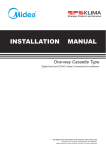
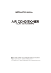
INSTALLATION
MANUAL
Middle Static Pressure Duct Type
Digital Scroll and DC/AC Inverter Commercial Air-conditioner
Thank you very much for purchasing our air conditioner,
Before using your air conditioner , please read this manual carefully and keep it for future reference.
CONTENTS
PAGE
PRECAUTIONS.......................................................................................... 1
When installing the unit in a small room, take measures
against to keep refrigerant concentration from exceeding
allowable safety limits in the event of refrigerant leakage.
Contact the place of purchase for more information. Excessive
refrigerant in a closed ambient can lead to oxygen deficiency.
INSTALLATION INFORMATION.................................................................. 2
ACCESSORIES.......................................................................................... 3
INSPECTING AND HANDLING THE UNIT................................................... 3
INTDOOR UNIT INSTALLATION ................................................................ 3
INSTALL THE CONNECTING PIPE..............................................................8
REFRIGERANT PIPE CONNECTION............................................................9
CONNECT THE DRAIN PIPE.....................................................................10
MOTOR AND DRAIN PUMP MAINTENANCE.............................................12
WIRING...................................................................................................12
CONTROL OPERATION.............................................................................13
TEST OPERATION....................................................................................15
Use the attached accessories parts and specified parts for
installation.
Otherwise, it will cause the set to fall, water leakage, electrical
shock fire.
Install at a strong and firm location which is able to
withstand the set's weight.
If the strength is not enough or installation is not properly done,
the set will drop to cause injury.
The appliance must be installed 2.5m above floor.
The appliance shall not be installed in the laundry.
Before obtaining access to terminals, all supply circuits
must be disconnected.
1.
PRECAUTIONS
Precautions before reading the Installation manual.
This Installation manual is for the indoor unit.
Refer to the indoor unit Installation manual for indoor parts
installation.
Please read the power source unit Installation manual to install
the power source unit.
Please refer to the refrigerant distributor Installation manual to
install the refrigerant distributor.
The safety precautions listed here are divided into two categories. In
either case, important safety information is listed which must be read
carefully.
WARNING
Failure to observe a warning may result in death.
CAUTION
Failure to observe a caution may result in injury or damage
to the equipment.
After completing the installation, make sure that the unit operates
properly during the start-up operation. Please instruct the customer
on how to operate the unit and keep it maintained. Also, inform
customers that they should store this Installation manual along with
the owner's manual for future reference.
WARNING
Be sure only trained and qualified service personnel to
install, repair or service the equipment.
Improper installation, repair, and maintenance may result in
electric shocks, short-circuit, leaks, fire or other damage to the
equipment.
The appliance must be positioned so that the plug is
accessible.
The enclosure of the appliance shall be marked by word, or
by symbols, with the direction of the fluid flow.
For electrical work, follow the local national wiring
standard, regulation and this installation instructions. An
independent circuit and single outlet must be used.
If electrical circuit capacity is not enough or defect in electrical
work, it will cause electrical shock fire.
Use the specified cable and connect tightly and clamp the
cable so that no external force will be acted on the
terminal.
If connection or fixing is not perfect, it will cause heat-up or fire
at the connection.
Wiring routing must be properly arranged so that control
board cover is fixed properly.
If control board cover is not fixed perfectly, it will cause heat-up
at connection point of terminal, fire or electrical shock.
If the supply cord is damaged, it must be replaced by the
manufacture or its service agent or similarly qualified
person in order to avoid a hazard.
An all-pole disconnection switch having a contact
separation of at least 3mm in a poles should be connected
in fixed wiring.
When carrying out piping connection, take care not to let
air substances go into refrigeration cycle.
Otherwise, it will cause lower capacity, abnormal high pressure
in the refrigeration cycle, explosion and injury.
Do not modify the length of the power supply cord or use
of extension cord, and do not share the single outlet with
other electrical appliances.
Otherwise, it will cause fire or electrical shock.
Carry out the specified installation work after taking into
account strong winds, typhoons or earthquakes.
Improper installation work may result in the equipment falling
and causing accidents.
Install according to this installation instructions strictly.
If installation is defective, it will cause water leakage, electrical
shock fire.
Installation manual
1
If the refrigerant leaks during installation, ventilate the
area immediately.
Toxic gas may be produced if the refrigerant comes into the
place contacting with fire.
The temperature of refrigerant circuit will be high, please
keep the interconnection cable away from the copper
tube.
After completing the installation work, check that the
refrigerant does not leak.
Toxic gas may be produced if the refrigerant leaks into the
room and comes into contact with a source of fire, such as a
fan heater, stove or cooker.
CAUTION
Ground the air conditioner.
Do not connect the ground wire to gas or water pipes,
lightning rod or a telephone ground wire.Incomplete
grounding may result in electric shocks.
Be sure to install an earth leakage breaker.
Failure to install an earth leakage breaker may result in
electric shocks.
Connect the outdoor unit wires , then connect the indoor
unit wires.
You are not allowed to connect the air conditioner with the
power source until wiring and piping the air conditioner is
done.
While following the instructions in this installation
manual, install drain piping in order to ensure proper
drainage and insulate piping in order to prevent
condensation.
Improper drain piping may result in water leakage and
property damage.
Install the indoor and outdoor units, power supply wiring
and connecting wires at least 1 meter away from
televisions or radios in order to prevent image
interference or noise.
Depending on the radio waves, a distance of 1 meter may not
be sufficient enough to eliminate the noise.
The appliance is not intended for use by young children
or infirm persons without supervision.
Don't install the air conditioner in the following locations:
There is petrolatum existing.
There is salty air surrounding (near the coast).
There is caustic gas (the sulfide, for example) existing
in the air (near a hot spring).
The Volt vibrates violently (in the factories).
In buses or cabinets.
In kitchen where it is full of oil gas.
There is strong electromagnetic wave existing.
There are inflammable materials or gas.
There is acid or alkaline liquid evaporating.
Other special conditions.
Installation manual
2
2.
INSTALLATION INFORMATION
To install properly, please read this "installation manual" at
first.
The air conditioner must be installed by qualified persons.
When installing the indoor unit or its tubing, please follow
this manual as strictly as possible.
If the air conditioner is installed on a metal part of the
building, it must be electrically insulated according to the
relevant standards to electrical appliances.
When all the installation work is finished, please turn on
the power only after a thorough check.
Regret for no further announcement if there is any change
of this manual caused by product improvement.
INSTALLATION ORDER
Select the location;
Install the indoor unit;
Install the outdoor unit;
Install the connecting pipe ;
Connect the drain pipe;
Wiring;
Test operation.
3. ACCESSORIES
5.
Table.3-1
Outline
Installation manual
1
(This manual)
Usage
Wire controller
1
Wire control the
air-conditioner
Pipe insulation material
2
Heat insulation
Adhesive tape for seal
1
To connect drain pipe
Water outlet joint
1
For drainage
1
Chucking the joint which
connect the drain hose
and the outlet of indoor
unit
1
The indoor unit which at
the terminal of
communication system
shouldconnect a
impedance between port
P and port Q
Clasp
Network matching wire
Maintenance roomage
500mm or mo re
Q‘ty
Confirm that there is enough room for installation and maintenance.
Maintenance roomage
600mm or mo re
Name of
Accessories
INDOOR UNIT INSTALLATION
600mmX600mm
checking orifice
Fig.5-1
Confirm the minimum
drain tilt is 1/100 or more
checking orifice
Cautions on wire controller installation
●
Never throw or beat the controller.
●
Before installation, operate the wire controller to determine its
location in a reception range.
●
Keep the wire controller at least 1m apart from the nearest TV
set or stereo equipment. (It is necessary to prevent image disturbances or noise interferences.)
●
Do not install the wire controller in a place exposed to direct
sunlight or close to a heatingsource, such as a stove.Note that
the positive and negative poles are in right positions when
loading batteries.
4.
INSPECTING AND HANDLING THE UNIT
At delivery, the package should be checked and any damage should
be reported immediately to the service agent.
When handling the unit, take into account the following:
1
2
Fragile, handle the unit with care.
Choose on before hand the path along which the unit is to be
brought in.
3
Move this unit as originally package as possible.
4
When lifting the unit , always use protectors to prevent belt
damage and pay attention to the position of the unit’s centre
of gravity.
Fig.5-2
5.1 Installation Φ10 Hanging Screw Bolts (4 Bolts)
Please refer to the following figure for
measurement between the screw bolts.
the distance
Please install with Φ10 hanging screw bolts.
The handling to the ceiling varies from the constructions, consult
the construction personnels for the specific procedures.
●
The size of the ceiling to be handled ... ... do keep the ceiling
flat. Consolidate the roof beam for possible vibration.
●
Cut off the roof beam.
●
Strengthen the place cut off, and consolidate the roof beam.
Carry out the pipe and line operation in the ceiling after
finishing the installation of the main body. While choosing where
to start the operation, determine the direction of the pipes to be
drawn out. Especially in case there is a ceiling, position the
refrigerant pipes, drain pipes, indoor & outdoor lines to the
connection places before hanging up the machine.
The installation of hanging screw bolts.
Installation manual
3
5.2 Wooden construction
Put the square timber tra versely ove r the ro of beam, th en
install the hanging screw bolts. (Refer to Fig.5-3)
5.7 Diagrammatic sketch for Installing the
main body
Installing the dust proof net and canvas air passage
Timber over the beam
(1) Install the dust proof net according to the installation manual;
(2) Install the canvas air passage underneath the dust proof net.
Ro of beam
Ce iling
Ha nging screw bolts
Fig.5-3
5.3 New concrete bricks
Inlaying or embedding the screw bolts (refer to Fig.5-4)
5.8 Duct Design
(1) Air inlet and air outlet duct should be apart far enough to
prevent air outlet entering Air Inlet.
(2) There is dust filter on the indoor unit.
Recommended duct connection
Blade shape insertion
Canvas tie-in
Slide insertion
Canvas tie-in
Fig.5-4
5.4 For original concrete bricks
Isolation booth
Use embeding screw bold, crock and stick harmess (refer to
Fig.5-5)
Air outlet
Air inlet
Isolation booth
checking orifice
Steel bar
Air dust filter
Embedding screw bolt
Fig.5-8
(Pipe hanging and embedding screw bolt)
Fig.5-5
NOTE
5.5 Steel roof beam structre
Install and use directly the supporting angle steel. (refer to
Fig.5-6)
Hanging screw bolt
Hanging bolts
Supporting
angle steel
Fig.5-6
5.6 Overhanging the indoor unit
(1) Overhang the indoor unit onto the hanging screw bolts with
block.
(2) Position the indoor unit in a flat level by using the level indicator,
unless it may cause leakage.
Screw nut
Shockproof cushion
Washer
Hanging
screw bolt
Overhang part
Fig.5-7
Installation manual
4
1. Do not put the connecting duct weight on the indoor unit.
2. When connecting duct, use inflammable canvas tie-in to prevent
vibrating.
3. When connecting duct, install in place prone to takedown for
maintenance.
4. Change the fan motor static pressure corresponding to external
duct static pressure.
5. If installed in place like meeting room where noise is easy to be
perceived, design isolation booth and internal duct underlayer to
muffle the duct system and weaken the air encounter noise in the
duct.
■
The positioning of ceiling hole and indoor unit and hanging screw bolts
routine method of installation: the size of installation for indoor unit following the Fig.5-9 and the Table 5-1
Outline dimension and air outlet opening size
Unit: mm
Air return opening size
Air filter
Position size of descensional ventilation opening
Air filter
Electric control cabinet
Size of mounted lug
Electric control cabinet
Fig.5-9
Installation manual
5
Table.5-1
air outlet opening size
Outline dimension
air return opening size
Size of mounted lug
A
B
C
D
E
F
G
H
I
J
K
L
M
N
O
P
22~36
700
210
635
570
790
65
493
35
119
595
200
80
740
350
26
20
45~56
920
210
635
570
1010
65
713
35
119
815
200
80
960
350
26
20
71
920
270
635
570
1010
65
713
35
179
815
260
20
960
350
26
20
80~112 1140
270
775
710
1230
65
933
35
179
1035
260
20
1180
490
26
20
1200
300
865
800
1290
80
993
40
204
1094
288
45
1240
500
26
20
140
Table.5-2
Pipe Material
Mode
Size(mm)
Copper Pipe for Air Conditioner
2200~4500
5600~9000
10000~14000
F(Liquid side)
Φ6.4
Φ9.5
Φ9.5
G(Gas side)
Φ12.7
Φ15.9
Φ15.9
Refrigerant
R410A
■ How to adjust the air ventilated direction? (From rear ventilated adjust it to descensional.)
1.
2.
Take off ventilation panel and flange, cut off the staples at
side rail.
Air return flange
Stick the attached seal sponge as per the indicating place in
the following fig, and then change the mounting positions of
air return panel and air return flange .
Side rail
Dentilation panel
3.
When install the filter mesh, please plug it into flange inclined
from air return opening, and then push up.
Seal sponge
4.
The installation has finish, upon filter mesh which fixing
blocks have been insert to the flange positional holes.
Fig.5-10
NOTE
All the pictures in this manual are for explanation purpose only. They may be slightly different from the air conditioner you purchased
(depend on model).The actual shape shall prevail.
Installation manual
6
5.9 Fan performances
Static pressure curve
(Pa)
MODEL 22~36
(Pa)
MODEL 71
80
Supper High speed(reserved)
Supper High speed(reserved)
External static pressure (Pa)
60
High speed
50
Medium speed
40
30
High speed
External static pressure (Pa)
70
Low speed
Medium speed
Low speed
20
10
200
400
600
800
Air volume(m3/h)
Fig.5-13
Fig.5-11
(Pa)
(Pa)
MODEL 45~56
MODEL 80~90
Supper High speed
(reserved)
Supper High speed(reserved)
High speed
Medium speed
External static pressure (Pa)
External static pressure (Pa)
High speed
Medium speed
Low speed
Low speed
Air volume(m3/h)
Air volume(m3/h)
Fig.5-12
Fig.5-14
Installation manual
7
6.
Check whether the height drop between the indoor unit and
outdoor unit, the length of refrigerant pipe, and the number of the
bends meet the following requirements:
MODEL 112
(Pa)
220
●
The max height drop and The length of refrigerant pipe deponding
on the ouotdoor unit.(If the height drop is more than 10m, you
had better put the outdoor unit over above the indoor unit.)
●
The number bends fewer than 15
●
Do not let air, dust, or other impurities fall in the pipe system
during the time of installation.
●
The connecting pipe should not be installed until the indoor and
outdoor units have been fixed already.
●
Keep the connecting pipe dry, and do not let moisture in during
installation.
200
External static pressure (Pa)
180
Supper High speed
(reserved)
160
140
120
INSTALL THE CONNECTING PIPE
High speed
Medium speed
100
80
Low speed
The Procedure of Connecting Pipes
Measure the necessary length of the connecting pipe, and make
it by the following way.
60
40
●
Connect the indoor unit at first, then the outdoor unit.
①
Bend the tubing in proper way. Dont harm them.
②
Daub the surfaces of the flare pipe and the joint nuts with frozen
oil, and wrench it for 3~4rounds with hands before fasten the
flare nuts. (Refer to Fig.6-1)
③
Be sure to use two wrenches simultaneously when you connect
or disconnect the pipes.
●
The stop valve of the outdoor unit should be closed absolutely
(as original state). Every time you connect it, first loosen the nuts
at the part of stop valve, then connect the flare pipe immediately
(in 5 minutes). If the nuts have been loosened for a long time,
dusts and other impurities may enter the pipe system and may
cause malfunction later. So please expel the air out of the pipe
with refrigerant before connection.
●
Expel the air (refer to the “Expel The Air”) after connecting the
refrigerant pipe with the indoor unit and the outdoor unit.Then
fasten the nuts at the repair-points.
20
400 800 1200 1600 2000 2400 2800
Air volume(m3/h)
Fig.5-15
(Pa)
MODEL 140
External static pressure (Pa)
Supper High speed
(reserved)
Notices For Benable pipe.
High speed
Medium speed
Fig.5-16
8
The bending angle should not exceed 90°C
●
Bending position is preferably in the bendable pipe. The larger
the better it is .
●
Do not bend the pipe more than three times.
Bend the connecting pipe of small wall thickness.
Low speed
Air volume(m3/h)
Installation manual
●
●
Cut out a desired concave at the bending part of the insulating
pipe.
●
Then expose the pipe(cover it with tapes after bending).
●
To prevent collapsing of deforming, please bend the pipe at its
biggest radius.
●
Use bender to get a small radius pipes.
Use the market brass pipe.
Be sure to use the same insulating materials when you buy the
brass pipe. (More than 9mm thick).
90 °± 4
45 °
±2
A
Use frozen oil
R0.4~0.8
Fig.7-2
Fig.6-1
Table.7-1
A(mm)
Outside diameter
Bend the pipe with thumb
Fig.6-2
Make the ends
straight
Max
Min
Φ6.4mm
8.7
8.3
Φ9.5mm
12.4
12.0
Φ12.7mm
15.8
15.4
Φ15.9mm
19.0
18.6
Φ19.1mm
23.3
22.9
Fig.6-3
Fasten the nut
Locate The Pipe
●
Drill a hole in the wall (suitable just for the size of the wall conduit,
90mm in general), then set on the fittings such as the wall conduit
and its cover.
●
Bind the connecting pipe and the cables together tightly with
binding tapes. Do not let air in, which will cause water leakage
by condensation.
●
Pass the bound connecting pipe through the wall conduit from
outside. Be careful of the pipe all ocation to do no damage to the
tubing.
●
Put the connecting tubing at the proper position, wrench the
nuts with hands then fasten it with a wrench. (Refer to
Fig.7-3)
●
Too large torque will harm the bellmouthing and too small will
cause leakage. Please determine the torque according to
Table.7-2.
Fig.7-3
Connect the pipes.
Table.7-2
Then, open the stem of stop valves of the outdoor unit to make the refrigerant pipe connecting the indoor unit with the outdoor unit
fluently flow.
Be sure of no leakage by checking it with leak detector or soap
water.
Cover the joint of the connecting pipe to the indoor unit with the
sound proof/insulating sheath (fittings), and bind it well with the
tapes to prevent leakage.
Tubing size
Torque
Φ6.4mm
14.2~17.2 N.m (144~176 kgf.cm)
Φ9.5mm
32.7~39.9 N.m (333~407 kgf.cm)
Φ12.7mm
49.5~60.3 N.m (504~616 kgf.cm)
Φ15.9mm
61.8~75.4 N.m (630~770 kgf.cm)
Φ19.1mm
97.2~118.6 N.m (990~1210 kgf.cm)
The necessary filling amount of refrigerant
7. REFRIGERANT PIPE CONNECTION
●
Refrigerant volume to be added is calculated according to
outdoor unit installation manual .Be sure to add refrigerant
measuring by a scale. L: The length of the pipe
●
Please record the quantity added and store it carefully for future
maintenance.
7.1 Expel The Air
Flaring
Expel the air with a vacuum pump (Refer to Fig.7-4) (Please
refer to its manual for the way of using manifold valve)
●
Cut a pipe with a pipe cutter.
●
Insert a flare nut into a pipe and flare the pipe.
Lean
crude
●
Loosen and remove the maintenance nuts of stop valves A
and B, and connect the charge hose of the manifold valve with
the maintenance terminator of stop valve A. (Be sure that stop
valves A and B are both closed)
●
Connect the joint of the charge hose with the vacuum pump.
●
Open the Lo-lever of the manifold valve completely.
burr
90
Fig.7-1
Installation manual
9
●
Turn on the vacuum pump. At the beginning of pumping, loosen
the maintenance terminator nut of stop valve B a little to check
whether the air comes in (the sound of the pump changes, and
the indicator of compound meter turns below zero). Then fasten
the nut.
●
When the pumping has finished, close the Lo-lever of the
manifold valve completely and turn off the vacuum pump.
●
When you have pumped for over 15 minutes, please confirm
that the indicator of multimeter is on -1.0X10⁵Pa (-76cmHg)
●
Loosen and remove the quadrangle cover of stop valves A
and B to open stop valve A and B completely, then fasten them.
●
Disassemble the charge hose from the repair-mouth of stop
valve A, and fasten the nut.
Manifold valve
Multi-meter
7.3 Insulation
Be sure to with insulating materials cover all the exposed parts
of the flare pipe joints and refrigerant pipe on the liquid-side and
the gas-side. Ensure that there is no gap between them.
Incomplete insulation may cause water condensation.
8.
CONNECT THE DRAIN PIPE
Install the drainpipe of the indoor unit
Please use the accessory drain hose to connect the outlet of
indoor unit with the PVC water pipe, and then use the
accessory the clasp for chucking(Refer to Fig.8-1).
Connections of other water pipes please use rigid PVC
binder, and confirm there whether have leakage or not.
Pressure meter
-76 cmHg
Lo-lever
Hi-lever
Charge hose
Indoor unit
Charge hose
Clasp
Water outlet joint
PVC water pipe(Φ25)
Vacuum pump
Outlet
Lo-lever
Rigid PVC binder
Fig.7-4
Fig.8-1
All the stop valves should be opened before test operation.
Each air conditioner has two stop valves of different sizes on
the side of the outdoor unit which operate as Lo-stop value,
respectively. (Refer to Fig.7-5)
Flare nut
Do not drag the drainpipe violently when connecting to
prevent the body from being pulled. Meanwhile, one
supportpoint should be set every 0.8~1.0m to prevent the
drainpipe from yielding. Or you can tie the drainpipe with the
connecting pipe to fix it.
Stopper
Cap
In the case of prolonged drainpipe, you had better tighten its
indoor part with a protection tube to prevent it from loosing.
Valve body
Valve stem
Fig.7-5
7.2 Check The Leakage
Check all the joints with the leak detector or soap water. (See
Fig.7-6 as a reference illustration)
Check-point of indoor unit
Check-point of outdoor unit
D
C
B
A
Fig.7-6
10
In case the drainpipe outlet is higher than pumping
connective pipe of the main body, the drainpipe must be
arranged upwards vertically by using connective assembly of
the water outlet for vertical bending, and the height of the
drainpipe shall set to the defrosting pan surface no more than
600mm, otherwise, too much backflow while shutdown would
leads to overflow (Refer to Fig.8-2).(Only available for the unit
with pump.)
The end of the drainpipe should be over 50mm higher than
the ground or the bottom of the drainage chute, and do not
immerse it in water. If you discharge the water directly into
sewage, be sure to make a U-form aquaseal by bending the
A......Lo-stop valve
B......Hi-stop valve
C,D..Joints of the connecting pipe to the indoor unit.
Installation manual
To prevent water from flowing backwards into the air
conditioner while the air conditioner stops, please lean the
drainpipe down toward outdoor (outlet-side) at a degree of
over 1/ 100. And please avoid any bulge or water deposit.
The drain pipe installation for the unit with pump.
0.8-1.0m
Lean over 1/100
Max. 600mm
<200mm
Fig.8-2
The drain pipe installation for the unit without pump.
0.8-1.0m
Stow tube
Fig.8-5
Lean over 1/100
Fig.8-3
2
Turn on the power, and operate the air conditioner under the
"COOLING" mode. Listen to the sound of the drain pump.
Check whether the water is discharger well (a lag of 1min is
allowed before discharging, according to the length of the drain
pipe), and check whether water leaks from the joints.
3
Stop the air conditioner, turn off the power, and reset the test
cover to its original position.
Drainage test
Check whether the drainpipe is unhindered.
New built house should have this test done before paving
the ceiling.
The unit without pump.
The unit with pump.
Remove the test cover (Rotate the test cover to opening up),
and stow water of about 2000ml to the water receiver through
the stow tube.
Fig.8-6
Remove the test cover, and stow water of about 2000ml to the
water receiver through the stow tube,check whether the
drainpipe is unhindered.
OPEN
CLOSED
N
OPE
Test cap
CLOSED
1
Fig.8-4
Installation manual
11
9. MOTOR AND DRAIN PUMP MAINTENANCE
(Take rear ventilated as example)
Motor maintain:
1. Remove off the ventilated panel.
2. Remove off a half of motor housing.
3. Take off the motor.
Electronic expansion valve components
Piping binder plate
Fig.9-3
Motor
10. WIRING
Attaching wiring
Blower housing
●
The air conditioner should use separate power supply with
rated voltage.
●
The external power supply to the air conditioner should have
ground wiring, which is linked to the ground wiring of the indoor
and outdoor unit.
●
The wiring work should be done by qualified persons according
to circuit drawing.
●
A leakage protector should be installed according to the National
Standard concerning electrical appliance.
●
Be sure to locate the power wiring and the signal wring well to
avoid cross-disturbance and their contact with connecting pipe
or stop value body.
●
Generally, do not twist two wiring together unless the joint is
soldered well and covered with insulator tape.
●
Do not turn on the power until you have checked carefully after
wiring.
Ventilated panel
Fig.9-1
Pump maintain:
1.
Screw off four screws from drain pump.
2.
Plug off pump power supply and water level switch cable.
3.
Take off pump.
The Specification of Power.
Table.10-1
Model(W)
2200~14000
Phase
Power
Power
switch
Pump
Fig.9-2
Electronic expansion valve components
1-Phase
220-240V~ 50Hz
208-230V~ 60Hz
Frequency and volt
Capacity
15A
Safety fuse
Indoor unit power wiring
15A
(mm2)
Indoor/outdoor connectingwiring
(mm2) (Electric signal)
3×2.5
3-core shielded wire 3×0.75
maintain:
1. Take down the screws on the piping binder plate(Fig.9-3)
2. Use two spanners to carefully unscrew the copper nuts of the
electronic expansion valve components and the piping
connectors.
3. Take down the electronic expansion valve components.
Installation manual
12
CAUTION
A disconnection device having an air gap contact separation in
all active conductors should be incorporated in the fixed wiring
according to the National Wiring Regulation.
11.
Wiring chart
Power (220-240V~ 50Hz
208-230V~ 60Hz)
CONTROL OPERATION
11.1 Horsepower set
Horsepower code
PO WER_S
EF 0
ABC
123 4
D
I NDOO R UNIT
56
789
CENTRAL CONTROL
MONITOR(CCM)
ENC1
COM PUTER
I NDOO R UNIT
Base on different purposes to setting the switch cords on PC panel
of indoor electrical control box. Once finish the setting, please cut off
the main power, and then input power again, otherwise, setting
function could not work.
OUTDOOR UNIT
I NDOO R UNIT
Table.11-1
3-core shieled wire
ENC1
Fig.10-1
CAUTION
The reserved function is indicated in broken line table,users can
select it when necessary.
Terminal board diagram
Please refer to the indoor unit wiring diagram for the wiring.
NOTE
The air-conditioners can connect with Central Control Monitor
(CCM). Before operation, please wiring correctly and set
system address and network address of indoor units.
Note: The horsepower
has been set before
leaving the factory ,
anyone can’t
modify it except the
maintenance person.
Toggle switch
For set horsepower
Code
Capacity(Horsepower)
0
2200W(0.8HP)
1
2800W(1.0HP)
2
3600W(1.2HP)
3
4500W(1.7HP)
4
5600W(2.0HP)
5
7100W(2.5HP)
6
8000W(3.0HP)
7
9000W(3.2HP)
8
11200W(4.0HP)
9
14000W(5.0HP)
CAUTION
The system together have 64units(0-63),everyone has only
system addresscode,If two addresses are the same in one
system , the abnormal operation will occur.
L
N
Please switch off the power before setting,otherwise the
unexpected error will occur.
To indoor power
220-240V~ 50Hz
208-230V~ 60Hz
Fig.10-2
Please use 3-core shielded wire,and connect the shielded layer to
X
Y
E
P
Q
To Central Control Indoor/outdoor
connection wire
Monitor (CCM)
.
11.2 Network address set
1) Network address is set by communication of indoor and
outdoor unit; the address is the same as indoor address, there
is no need to set separately.
2) The central control of indoor units can be done on outdoor
unit, there is no need to control indoor unit separately, for
details please refer to V4+ outdoor unit manual.
3) For previous control of indoor units, the network can be set
by connecting (X,Y,E) terminals, there is no need to set
network address. The network can also be set by outer
network module and main board (CN20).
Fig.10-3
Installation manual
13
11.3 Main board Code designation
SW1 definition
ON
ON
ON
SW1
1234
SW1
1234
SW1
● 1 means factory test mode
● 0 means add. auto searching mode
(default setting)
● 1 means DC fan Is chosen
● 0 means AC fan Is chosen
SW1
ON
1234
SW1
ON
● 10 means DC fan static pressure is 2
1234
● 00 means DC fan static pressure is 0
(reserved)
SW1
ON
1234
● 01 means DC fan static pressure is 1
(reserved)
1234
(reserved)
● 11 means DC fan static pressure is 3
(reserved)
SW2 definition
ON
ON
ON
ON
S W2
12 34
S W2
12 34
S W2
12 34
S W2
12 34
● 00 means the temperature is 15
degrees when shutting down the unit
for cold wind proof.
● 01 means the temperature is 20
degrees when shutting down the
unit for cold wind proof.
● 10 means the temperature is 24
degrees when shutting down the
unit for cold wind proof.
● 11 means the temperature is 26
degrees when shutting down the
unit for cold wind proof.
SW2
ON
● 00 means the time of stopping
1234
SW2
ON
TERMAL fan is 4 minutes
● 01 means the time of stopping
TERMAL fan is 8 minutes
1234
SW2
ON
ON
● 10 means the time of stopping
TERMAL fan is 12 minutes
1234
SW2
1234
● 11 means the time of stopping
TERMAL fan is 16 minutes
SW5 definition
ON
SW 5
● 00 means temperature compensation is
6 degrees under heating mode
ON
1 2
ON
● 01 means temperature compensation is
2 degrees under heating mode
ON
ON
1 2 3
SW6
1 2 3
ON
SW6
1 2 3
Installation manual
14
is 4 degrees under heating mode
ON
SW5
● 11 means temperature compensation
is 8 degrees under heating mode
1 2
J1,J2 definition
SW6 definition
SW6
● 10 means temperature compensation
1 2
SW 5
1 2
SW5
J1
● 1 means old display panel
J1 no Jumpers means power
off memory function
● 0 means new display panel
J1
J1 Jumpers means no power
off memory function
● 1 means auto wind under auto mode
● 0 means auto wind under non auto mode
J2
reserved
reserved
SW7 definition
ON
SW7
Standard configure
1 2
ON
SW7
Last one in the network
1 2
Means 0
ON
2) The outdoor unit
a. Whether there is vibration or abnormal noise during
operation.
b. Whether the generated wind, noise, or condensed of by
the air conditioner have influenced your neighborhood.
c. Whether any of the refrigerant is leaked.
CAUTION
0/1 definition
ON
h. Whether there is vibration or abnormal noise during
operation.
I. Whether the air conditioner heats well in the case of
the HEATING/COOLING type.
A protection feature prevents the air conditioner from being
activated for approximately 3 minutes when it is restarted
immediately after shut off.
Means 1
12. TEST OPERATION
1
The test operation must be carried out after the entire
installation has been completed.
2
Please confirm the following points before the test operation:
The indoor unit and outdoor unit are installed properly.
Tubing and wiring are correctly completed.
The refrigerant pipe system is leakage-checked.
The drainage is unimpeded.
The heating insulation works well.
The ground wiring is connected correctly.
The length of the tubing and the added stow capacity of
the refrigerant have been recorded.
The power voltage fits the rated voltage of the air
conditioner.
There is no obstacle at the outlet and inlet of the outdoor
and indoor units.
The gas-side and liquid-side stop valves are both opened.
The air conditioner is pre-heated by turning on the power.
3
According to the user's requirement, install the remote
controller frame where the remote controller's signal can
reach the indoor unit smoothly.
4
Test operation
Set the air conditioner under the mode of "COOLING" with the
remote controller, and check the following points. If there is
any malfunction, please resolve it according to the chapter
"Troubleshooting" in the "Owner's Manual".
1) The indoor unit
a. Whether the switch on the remote controller works well.
b. Whether the buttons on the remote controller works
well.
c. Whether the air flow louver moves normally.
d. Whether the room temperature is adjusted well.
e. Whether the indicator lights normally.
f. Whether the temporary buttons works well.
g. Whether the drainage is normal.
Installation manual
15