1
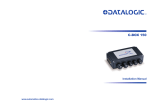
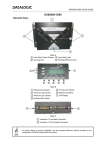
PWO-480 INSTALLATION MANUAL Datalogic Automation Srl Via Lavino, 256 40050 - Monte S. Pietro Bologna - Italy PWO-480 Installation Manual Ed.: 10/2010 © 2005 – 2010 Datalogic Automation S.r.l. ALL RIGHTS RESERVED. Protected to the fullest extent under U.S. and international laws. Copying, or altering of this document is prohibited without express written consent from Datalogic Automation S.r.l. Datalogic and the Datalogic logo are registered trademarks of Datalogic S.p.A. in many countries, including the U.S.A. and the E.U. Genius is a trademark of Datalogic Automation S.r.l. All other brand and product names mentioned herein are for identification purposes only and may be trademarks or registered trademarks of their respective owners. Datalogic shall not be liable for technical or editorial errors or omissions contained herein, nor for incidental or consequential damages resulting from the use of this material. 821001193 (Rev. D) CONTENTS SAFETY REGULATIONS ........................................................................................... iv Electrical Safety ........................................................................................................... iv SERVICES AND SUPPORT ....................................................................................... iv GENERAL VIEW .......................................................................................................... v GUIDE TO INSTALLATION ........................................................................................ vi 1 1.1 1.2 1.3 INTRODUCTION .......................................................................................................... 1 Product Description ...................................................................................................... 1 Accessories .................................................................................................................. 1 System Layouts ............................................................................................................ 2 2 2.1 2.2 2.3 2.4 2.5 2.6 2.6.1 2.6.2 2.6.3 2.6.4 2.6.5 2.7 2.7.1 2.7.2 2.7.3 2.7.4 2.7.5 2.7.6 2.7.7 INSTALLATION ........................................................................................................... 4 Mechanical Installation ................................................................................................. 4 PWO-480 Electrical Diagram........................................................................................ 5 PWO-480 Supply Capacity ........................................................................................... 6 Input Line Voltage......................................................................................................... 6 System Wiring to PWO-480.......................................................................................... 7 Switch Settings ............................................................................................................. 9 Bus Termination............................................................................................................ 9 Redundancy Selection.................................................................................................. 9 Redundancy Role ......................................................................................................... 9 Source ........................................................................................................................ 10 IN3 Selection .............................................................................................................. 10 Electrical Connections ................................................................................................ 10 SC6000 to PWO-480 .................................................................................................. 10 Lonworks .................................................................................................................... 11 PS/PS AUX/Encoder .................................................................................................. 12 Extended I/O............................................................................................................... 13 Host (Main) Interface .................................................................................................. 17 Modem........................................................................................................................ 19 Power Alarm ............................................................................................................... 19 3 TECHNICAL FEATURES........................................................................................... 20 Power Supply - I/O (Power/Net Connector)................................................................ 21 Extended I/O............................................................................................................... 22 Main Interface ............................................................................................................. 22 iii SAFETY REGULATIONS ELECTRICAL SAFETY This product conforms to the applicable requirements contained in the European Standard for electrical safety EN 60950-1 at the date of manufacture. This symbol refers to operations that must be performed by qualified personnel only. Example: opening the device. This symbol refers to operations where there is danger of electrical shock. Before opening the device make sure the power cable is disconnected to avoid electrical shock. The AC Plug Label appears as follows: The internal AC plug must only be used temporarily during system installation or maintenance. Maximum available power = 500 W Figure 1 – AC Plug Label SERVICES AND SUPPORT Datalogic provides several services as well as technical support through its website. Log on to www.automation.datalogic.com and click on the links indicated for further information: PRODUCTS Search through the links to arrive at your product page which describes specific Info, Features, Applications, Models, Accessories, and Downloads. SERVICE - Overview - Warranty Extensions and Maintenance Agreements - Sales Network- Listing of Subsidiaries, Repair Centers, Partners - Helpdesk - Material Return Authorization iv GENERAL VIEW PWO-480 1 2 3 Figure 2 – PWO-480 Closed View 4 5 6 7 8 9 Figure 3 – PWO-480 Open View 1 AC Line Gland 6 Bipolar Circuit Breaker 2 Key Locks 7 Monophase Switching Power Supply 3 Cable Glands 8 System Cable Connectors 4 AC Line Input Terminal Block 9 System Wiring Terminal Blocks 5 AC Plug (for temporary use only) v GUIDE TO INSTALLATION The following can be used as a checklist to verify all the steps necessary to complete installation of the PWO-480. Before wiring the device make sure the power is disconnected to avoid electrical shock. WARNING 1) Read all information in the section “Safety Precautions” at the beginning of this manual. 2) Mount the PWO-480 near the Reading Station. 3) With AC line voltage OFF, wire the AC Line input to the PWO-480 AC Terminal Block. 4) Connect the SC6000 Controller to the PWO-480 by means of the appropriate accessory cables (see par. 1.2). All system cables must pass through the glands. 5) Provide correct and complete system cabling to the PWO according to the signals (Lonworks, encoder P.S., etc) necessary for the layout of your application. (See all sub paragraphs under 2.5. All system cables must pass through the glands. 6) Set the Bipolar Circuit Breaker to the ON position. 7) Apply the AC line voltage from the building installation and check that the PWO-480 powers up correctly. 8) Close and lock the PWO-480 enclosure. The installation is now complete. vi INTRODUCTION 1 1 INTRODUCTION 1.1 PRODUCT DESCRIPTION The PWO-480 unit is intended to be used in Datalogic scanning systems where an SC6000 Controller unit is used as a supervisor of a DS8000 and/or DS6000 scanner network. The PWO-480 acts as a power supply for the overall system (controller and scanners), as well as a Junction Box for the SC6000 I/O and COM. One model is available: PWO-480, input 100-240 Vac, output 24 Vdc, 480 W power supply unit. 1.2 ACCESSORIES The following accessories are necessary to build a reading station that uses the PWO-480 Power Supply (the scanner-related accessories are not included in this list): Name Description Part Number CAB – SC6003 25-pin cable SC6000 to PWO, 3m (for Extended I/O connections) 93A051338 CAB – SC6013 25-pin cable SC6000 to PWO, 3m (for Power/Net connections) 93A051337 CAB – SC6103 9-pin cable SC6000 to PWO, 3m (for Main Host and Modem connections) 93A051294 CAB – PWO 03 17-pin cable PWO to PWO, 3m (for redundancy) 93A051295 MOD-SC6000 Modem for SC6000 (INSYS Modem 56K) 93ACC1776 1 PWO-480 1 1.3 SYSTEM LAYOUTS Host HUB ETHERNET NULL-MODEM Cable VAC INPUT AUX Power/Net CAB-SC6013 SC6000 PWO CAB-SC6003 Extended I/O LONWORKS ENCODER BTK-8100 Bus Return CAB-610x PS PS Aux CAB-81xx CAB-81xx CAB-81xx CAB-6310 DS8100A DS8100A CAB-610x up to 4 scanners DS6XXX BT-6000 Terminator DS8100A CAB-610x up to 4 scanners CAB-611x DS6XXX DS6XXX DS6XXX Example Single Controller Layout with DS8100A and DS6000 Series Scanners Host HUB ETHERNET NULL-MODEM Cable VAC INPUT SC6000 AUX Power/Net CAB-SC6013 PWO CAB-SC6003 Extended I/O LONWORKS ENCODER BTK-8100 Bus Return CAB-81xx CAB-81xx CAB-81xx A CAB-81xx C DX8200A DX8200A DX8200A G D DS8100A BTK-8100 Bus Return DS8100A CAB-81xx CAB-81xx B CAB-81xx E DS8100A PS PS Aux CAB-81xx F DX8200A Example Single Controller Layout with DX8200A and DS8100A Scanners 2 H DS8100A INTRODUCTION 1 to Host ETHERNET NULL-MODEM Cable SC6000 AUX Working Controller VAC INPUT Power/Net CAB-SC6013 PWO CAB-SC6003 Extended I/O LONWORKS ENCODER CAB-81xx PS PS Aux CAB-81xx CAB-81xx A CAB-81xx E C DX8200A DS8100A BTK-8100 G DX8200A DS8100A Redundancy CAB-PWO 03 to Host ETHERNET VAC INPUT SC6000 Power/Net CAB-SC6013 PWO CAB-SC6003 Extended I/O Protecting Controller LONWORKS ENCODER CAB-81xx CAB-81xx CAB-81xx B DX8200A PS PS Aux D DS8100A BTK-8100 CAB-81xx F DX8200A H DS8100A Example Redundant System Layout 3 PWO-480 2 2 INSTALLATION 2.1 MECHANICAL INSTALLATION The diagram below gives the overall dimensions of the PWO-480 and may be used for its installation. The four through holes (diam. 8.5 mm) on the back of the enclosure are for mechanical fixture. 380 [14.96] 210 [8.27] Ø8.5 n° 4 [Ø0.33] 560 [22.05] 124 [4.88] 600 [23.62] 30 [1.18] 179.5 [7.07] 60 [2.36] 40 [1.57] 147 [5.79] 147 [5.79] 340 [13.39] 155 [6.10] 33 [1.30] 40 [1.57] 27 [1.06] 21 [0.82] mm [in] 4 INSTALLATION 2 2.2 PWO-480 ELECTRICAL DIAGRAM Before opening the device make sure the power cable is disconnected to avoid electrical shock. WARNING L N PE AC Plug * Bipolar Protective Circuit Breaker Monophase Switching Power Supply AC DC Fan PWO-480 Electrical Diagram * The AC plug must only be used temporarily during system installation or maintenance. The maximum available power is 500 W. CAUTION 5 PWO-480 2 2.3 PWO-480 SUPPLY CAPACITY A general rule to consider is that each scanner requires both peak power and steady state power. Power distribution is performed simultaneously for all scanners. This means that the PWO-480 must bear the peak power draw of all the scanner motors starting up together. The maximum peak power propagated is 24 V x 26 A = 624 W, while the steady state (normal) power is 24 V x 20 A = 480 W. Due to these limits, the maximum number of scanners to be supplied is: Maximum Number of Scanners Power Supply Unit DS6000 DX6000 DS8100A DX8200A DS8100* DX8200* PWR-480 24 20 16 12 8 6 * DS8100 and DX8200 scanners have peak power (startup) consumption of 60W. 2.4 INPUT LINE VOLTAGE Wire according the following points: Primary wiring: Overcurrent protection should be provided by a 12 to 15 A building installation circuit breaker. Wiring methods from the branch circuit breaker to the PWO-480 power supply shall comply with the National Electric Code ANSI\NFPA. For primary wiring use a 3-conductor cable with minimum size 13 AWG for every conductor. Choose the overall cable diameter and UL Listed conduits accordingly. These conductors have to be inserted into the dedicated terminal blocks on the DIN rail (see diagram) which are marked Line (L) neutral (N) and Protection Earth (PE). The terminal block marked with the ground symbol is a special block which allows direct connection of the Protection Earth with the enclosure of the PWO-480. The AC input cable must be inserted through the AC Line Gland and the individual wires installed into the AC terminal block. protection cover Replace the protection cover over the spring clamp connector after correctly installing the wires. The AC plug can only be used temporarily during installation or maintenance procedures. AC Line Terminal Block with Protection Covers 6 INSTALLATION 2 2.5 SYSTEM WIRING TO PWO-480 System wiring is performed using standard accessory cables and direct wiring to terminal block connectors provided on the PCB inside the PWO-480. To insert system cables: Remove the upper gland block by unscrewing the 2 side screws and the 3 top screws. Use a screwdriver to pry apart the upper gland block from the lower gland block. Pass all system cables through the opening and attach the rubber glands around each cable. Slide each gland into the block making sure that each gland is rotated so that the split is horizontal. Insert gland block plugs in the unused cable slots in order to maintain IP65 protection. Place the block into position on the housing while adjusting the cable lengths as needed. Fix the block to the housing by tightening the 3 top screws and then the 2 side screws. 7 PWO-480 2 The following connectors and terminal blocks are available for system connections: Cable Connectors System Switches and SC6000 Bus Termination SC6000Power/Net signals SC6000 Extended I/O Modem (reserved) Host Main Serial Interface Redundancy (reserved) DS8K Lonworks Branches 1-4 8K Bus Termination DS6K Lonworks Branch Spring Clamp Connectors DS6K Power PWR Alarm Encoder, PS, PS Aux IN1, IN2, IN3 8 Modem Host (Main) OUT1, OUT2, OUT3 OUT4, OUT5, OUT6 REL1, REL2, REL3 INSTALLATION 2 2.6 SWITCH SETTINGS 2.6.1 Bus Termination The LON TERM switch must be in the ON position to provide Lonworks bus termination at the SC6000 side. For DS8K branches, the last scanner in each branch as well as any unused DS8K branches inside the PWO-480 must be terminated by a BTK-8100 Bus Terminator. The 8K TERM switches must be in the ON position if the network is made up exclusively of DS8K family scanners. If at least one DS6K family scanner is employed, these switches must be set to OFF. For the DS6K branch, the last scanner in the branch must be terminated by a BT-6000 Bus Terminator. The 8K BYP switches must be in the ON position if the network is made up exclusively of DS6K family scanners. If at least one DS8K family scanner is employed, these switches must be set to OFF. 2.6.2 Redundancy Selection The group of 6 REDUNDANCY switches enable/disable redundancy and must all be set to the same value. When all switches are set to 0 (default) redundancy is disabled. When all switches are set to 1 redundancy is enabled. 2.6.3 Redundancy Role The SEL switches define the redundancy role and must be both set to the same value. When in the STD position they set the SC6000/PWO-480 to Working. When in the REV position they set the SC6000/PWO-480 to Protecting. 9 PWO-480 2 2.6.4 Source The SRC switch defines the source signals (Presence Sensor or Remote Encoder) to the scanners. When SRC is in the PS position the Presence Sensor is passed to all the scanners in the system. This is the correct setting for Single Controller systems working in On-Line Operating Mode. When SRC is in the RE position the relative Remote Encoder is passed to each scanner branch. This setting is only for Redundant systems. 2.6.5 IN3 Selection The IN3 switches select the operation of the IN3 signal towards the SC6000 and must be both set to the same value. In position PWR (default), they provide internal PWO-480 24 Vdc power monitoring signals to be sent to the SC6000. The alarm threshold is 21.6 Vdc (nominal value –10%). Values between 21.6 and 24 Vdc are therefore considered in the proper operating range. In position IN3 they allow the user to connect an external configurable input like IN1 and IN2. 2.7 ELECTRICAL CONNECTIONS 2.7.1 SC6000 to PWO-480 The following connectors are used to connect the SC6000 to the PWO-480: 10 Connector Type Power/Net 25-pin female power supply, lonworks and input/output signals, use CAB-SC6013 Extended I/O 25-pin male I/O supply and extended I/O signals (optoisolated), use CAB-SC6003 Reserved Connect modem directly to SC6000, use CABSC6103. Host - Main 9-pin male RS232/RS485 connection, use CAB-SC6103 main serial INSTALLATION 2.7.2 2 Lonworks The PWO-480 allows connection between the SC6000 and the DS8K and/or DS6K family scanners on the Lonworks network. The following scanner connectors are used to connect each branch using the standard accessory cables. Connector Type DS8K Branches 1-4* 17-pin female power supply, Lonworks and system signals for: DS8100A, DX8200A or DS8100-x0x0** DS6K 9-pin female power supply, Lonworks and system signals for: DS6300, DS6400, DX6400 12-pin spring clamp for DS6K extended branch power * When DS8K scanners are connected, any unused DS8K branches inside the PWO-480 must be terminated by a BTK-8100 Bus Terminator ** DS8100-x0x0 scanners cannot be used together with the other scanners in a Lonworks network. DS8K Branches PWO-480 supports up to 4 DS8K scanner branches with up to 4 DS8100A scanners per branch or up to 3 DX8200A scanners. DS6K Branch PWO-480 supports 1 DS6K scanner branch with up to 24 scanners (DS6300 or DS6400) or up to 20 DX6400 scanners. The DS6K connector can supply up to 4 DS6000 series scanners using the standard CAB-610x cables. To extend this branch you can connect another 6 groups of three to four scanners each using the CAB-611x cable and CAB-610x combination bringing power to each group from the PWO-480 DS6K 12-pin spring clamp connector through the CAB-6310 cable to the DS6K scanner Main Interface connector (see the typical layout drawing in par. 1.3). DS6K Lonworks Extended Branch Power 12-Pin Spring Clamp Connector Pin Name Function 1-6 7-12 VS GND Supply Voltage for DS6K branch extensions Ground Reference for DS6K branch extensions 11 PWO-480 2 2.7.3 PS/PS AUX/Encoder The PS and Encoder signals (and PS Aux if used) are connected to PWO-480 on their relative 4-pin spring clamp connectors. Vext PWO PS/PS AUX/ENCODER V ENC, PS, PS AUX 4-pin spring clamp connectors 1/4 A/B 4/1 B/A Signal Ground Figure 4 - PNP Command Input with Electrical Isolation PWO Vext ENC, PS, PS AUX 4-pin spring clamp connectors 1/4 A/B 4/1 B/A PS/PS AUX/ENCODER V Signal Ground Figure 5 - NPN Command Input with Electrical Isolation PS/PS AUX ENCODER PWO 2 ENC, PS, PS AUX 4-pin spring clamp connectors V VS_INPUTS* 1/4 A/B 4/1 B/A 3 GND Signal Ground *VS_INPUTS is connected through the SC6000 25-pin Extended I/O connector and is short-circuit protected. Figure 6 - PNP Command Input Using System Power PS/PS AUX ENCODER PWO 2 ENC, PS, PS AUX 4-pin spring clamp connectors VS_INPUTS* 1/4 A/B 4/1 B/A 3 GND V Signal Ground *VS_INPUTS is connected through the SC6000 25-pin Extended I/O connector and is short-circuit protected. Figure 7 - NPN Command Input Using System Power 12 INSTALLATION 2.7.4 2 Extended I/O Inputs All command logic inputs are optocoupled on the SC6000. IN1, IN2, IN3 12-Pin Spring Clamp Connector Pin Name Function 1 2 3 4 5 6 7 8 9 IN1A VS_INPUTS GND IN1B IN2A VS_INPUTS GND IN2B PWR/IN3A 10 11 12 VS_INPUTS GND PWR/IN3B Configurable digital input 1 – polarity insensitive System power to inputs System power reference ground Configurable digital input 1 – polarity insensitive Configurable digital input 2 – polarity insensitive System power to inputs System power reference ground Configurable digital input 2 – polarity insensitive Output Power Monitor or Configurable digital input 3 – polarity insensitive System power to inputs System power reference ground Power Monitor or Configurable digital input 3 – polarity insensitive Vext PWO USER INTERFACE V IN1, IN2, IN3 12-pin spring clamp connector Signal A/B B/A Ground Figure 8 – PNP Command Input with Electrical Isolation PWO Vext A/B IN1, IN2, IN3 12-pin spring clamp connector USER INTERFACE V B/A Signal Ground Figure 9 - NPN Command Input with Electrical Isolation Isolation between the command logic and the SC6000 is maintained by powering the inputs with an external supply voltage (Vext). For convenience, the inputs can be powered using the VS_INPUTS signal on the PWO-480. In this case, however, the device is no longer electrically isolated. The VS_INPUTS signal is short-circuit protected. 13 PWO-480 2 The electrical features of these inputs are: Maximum voltage 30 V Maximum current 10 mA USER INTERFACE PWO V VS_INPUTS* IN1, IN2, IN3 12-pin spring clamp connector Signal A/B B/A Ground GND *VS_INPUTS is connected through the SC6000 25-pin Extended I/O connector and is short-circuit protected. Figure 10 - PNP Command Input Using System Power PWO USER INTERFACE VS_INPUTS* IN1, IN2, IN3 12-pin spring clamp connector V A/B B/A Signal GND Ground *VS_INPUTS is connected through the SC6000 25-pin Extended I/O connector and is short-circuit protected. Figure 11 - NPN Command Input Using System Power Outputs Six general purpose outputs are available. OUT1, OUT2, OUT3 12-Pin Spring Clamp Connector 14 Pin Name Function 1 2 3 4 5 6 7 8 9 10 11 12 OUT 1+ VS_OUTPUTS GND OUT 1OUT 2+ VS_OUTPUTS GND OUT 2OUT 3+ VS_OUTPUTS GND OUT 3- Configurable digital output 1 – positive pin System power to outputs System power reference ground Configurable digital output 1 – negative pin Configurable digital output 2 – positive pin System power to outputs System power reference ground Configurable digital output 2 – negative pin Configurable digital output 3 – positive pin System power to outputs System power reference ground Configurable digital output 3 – negative pin INSTALLATION 2 OUT4, OUT5, OUT6 12-Pin Spring Clamp Connector Pin Name Function 1 2 3 4 5 6 7 8 9 10 11 12 OUT 4+ VS_OUTPUTS GND OUT 4OUT 5+ VS_OUTPUTS GND OUT 5OUT 6+ VS_OUTPUTS GND OUT 6- Configurable digital output 4 – positive pin System power to outputs System power reference ground Configurable digital output 4 – negative pin Configurable digital output 5 – positive pin System power to outputs System power reference ground Configurable digital output 5 – negative pin Configurable digital output 6 – positive pin System power to outputs System power reference ground Configurable digital output 6 – negative pin The function of all six outputs can be defined by the user in software on the SC6000 through Genius™, refer to Genius™ Help On-Line for details. Isolation between the command logic and the SC6000 is maintained by powering the outputs with an external supply voltage (Vext). For convenience, the outputs can be powered using the VS_OUTPUTS signal on the PWO-480. In this case, however, the device is no longer electrically isolated. The VS_OUTPUTS signal is short-circuit protected. The electrical features of these outputs are: Collector-emitter voltage Collector current Saturation voltage (VCE) Maximum power dissipation 30 V Max. 130 mA Max. 1 V at 10 mA Max. 90 mW at 50°C (Ambient temperature). The limit requested by the maximum power dissipation is more important than that of the maximum collector current: if one of these outputs is continuously driven, the maximum current must not be more than 40 mA although 130 mA may be reached in pulse conditions. Vext PWO USER INTERFACE V OUT1, OUT2, OUT3 OUT4, OUT5, OUT6 12-pin spring clamp connectors + - Signal Ground Figure 12 - Open Collector Output Connection with Electrical Isolation 15 PWO-480 2 USER INTERFACE PWO VS_OUTPUTS* + OUT1, OUT2, OUT3 OUT4, OUT5, OUT6 12-pin spring clamp connectors V Signal - Ground GND *VS_OUTPUTS is connected through the SC6000 25-pin Extended I/O connector and is short-circuit protected. Figure 13 - Open Collector Output Connection Using System Power Relays There are three relay outputs available on the relative 12-pin spring clamp connector. REL1, REL2, REL3 12-Pin Spring Clamp Connector Pin Name Function 1 2 3 4 5 6 7 8 9 10 11 12 REL 1 NC REL 1 Common REL 1 NO Normally Closed pole Common pole Normally Open pole not connected Normally Closed pole Common pole Normally Open pole not connected Normally Closed pole Common pole Normally Open pole not connected REL 2 NC REL 2 Common REL 2 NO REL 3 NC REL 3 Common REL 3 NO Each relay can carry a 6.5 A load. USER INTERFACE PWO NO NC Common Signal Signal Ground REL1, REL2, REL3 12-pin spring clamp connectors Figure 14 - Relay Outputs 16 INSTALLATION 2.7.5 2 Host (Main) Interface The Host main serial interface is compatible with the following electrical standards: RS232 RS485 Full Duplex CAUTION Do not connect GND and GND_ISO to different (external) ground references. GND and GND_ISO are internally connected through filtering circuitry which can be permanently damaged if subjected to voltage drops over 0.8 Vdc. Details regarding the connections and use of the main interface selection are given in the next paragraphs. Host (Main) 12-pin Spring Clamp Connector Pinout Pin 1 2 3 4 5 RS232 TX RX RTS CTS GND_ISO RS485 Full Duplex TX485+ RX485+ TX485RX485GND_ISO RS232 Interface The main serial interface is used for communication between the SC6000 and the Host computer through the PWO and allows both transmission of code data and controller configuration. The following pins of the 12-pin spring clamp connector are used for RS232 interface connection: It is always advisable to use shielded cables. The overall maximum cable length must be less than 15 m (49.2 ft). Host (Main) RS232 12-pin Spring Clamp Connector Pinout Pin 1 2 3 4 5 Name TX RX RTS CTS GND_ISO Function Transmit Receive Request to send Clear to send Main signal ground The RTS and CTS signals control data transmission and synchronize the connected devices. If the RTS/CTS hardware protocol is enabled, the SC6000 activates the RTS output to indicate a message can be transmitted. The Host must activate the CTS input to enable the transmission. 17 PWO-480 2 Host PWO Host 12-pin spring clamp connector 1 TX 2 RX 5 GND-ISO 4 CTS 3 RTS RX TX Signal Ground RTS CTS Shield Figure 15 - RS232 Connections RS485 Full-Duplex Interface The RS485 full-duplex interface is used for non-polled communication protocols in point-topoint connections over longer distances (max 1200 m / 3940 ft) than those acceptable for RS232 communications or in electrically noisy environments. The following pins of the 12-pin spring clamp connector are used for RS485 full-duplex interface connection: Host (Main) RS485 12-pin Spring Clamp Connector Pinout Pin 1 2 3 4 5 Name TX485+ RX485+ TX485RX485GND_ISO Function RS485 transmit (+) RS485 receive (+) RS485 transmit (-) RS485 receive (-) Main signal ground Host PWO Host 12-pin spring clamp connector 1 TX485+ 2 RX485+ 5 GND_ISO 4 RX485- 3 TX485- RX+ TX+ Signal Ground TXRXShield Figure 16 - RS485 Full-Duplex Interface Connections 18 INSTALLATION 2.7.6 2 Modem The modem serial interface is used for communication between the SC6000 and the Host computer to remotely control the reading station. An accessory modem can be installed onto the DIN rail and powered inside the PWO. The SC6000 should be connected directly to the modem using CAB-SC6103. The telephone line can be directly connected to the accessory modem inside the PWO-480. The PWO-480 supplies power to the modem from the modem 12-pin spring clamp connector. Modem Power 12-pin Spring Clamp Connector Pinout Pin 11 12 Name Function Supply Voltage (24+ V) Ground VS GND See the Modem Installation document on the CD-ROM for complete installation and configuration details. 2.7.7 Power Alarm The PWO-480 provides lines to monitor the power supply output on the power alarm 4-pin spring clamp connector. This output can be used to control an external alarm in case of PWO power failure. The alarm threshold is 21.6 Vdc (nominal value –10%). Values between 21.6 and 24 Vdc are therefore considered in the proper operating range. When the power supply output level is in the range 21.6…24 Vdc, DC_OK has the same value as the output; it can be loaded with 40 mA max. to GND. When the power supply output level falls below 21.6 Vdc, DC_OK goes to 0 Vdc. Pin 2 is reserved for PWO internal use. Power Alarm 4-pin Spring Clamp Connector Pinout Pin 1 2 3 4 Name Function Ground Reserved Power Out OK Signal No Connection GND Reserved DC_OK N.C. PWO USER INTERFACE Vext 3 PWR ALARM 4-pin spring clamp connectors DC_OK Alarm 1 GND Figure 17 – Example Power Alarm Output 19 PWO-480 3 3 TECHNICAL FEATURES ELECTRICAL FEATURES Input Voltage Input Current Nominal Output Current Maximum Output Current Output Voltage ENVIRONMENTAL FEATURES Operating Temperature Storage Temperature Humidity Vibration Resistance AC from 85 to 264 V from 45 to 65 Hz 6.73 A @ 85 V; 2.12 A @ 264 V 20 A 26 A (up to +40 °C) 24 VDC 1% Protection Class -25° to +50 °C (-13° to +122 °F) -40° to +85 °C (-40° to +185 °F) 90% non condensing EN 60068-2-6 Frequency range from 5 to 150 Hz; Constant displacement 3 mm pk-pk from 5 to 9 Hz; Constant acceleration 0.5 g from 9 to 150 Hz 2 hours on each axis EN 60721-3-3 250 m/s², 6 ms 3 + 3 shocks on each axis IP65* PHYSICAL FEATURES Mechanical Dimensions Weight 600 x 407 x 210 mm (23.6 x 16 x 8.3 in) 19.2 kg. (42 lbs 5 oz.) Shock Resistance * when all unused gland blocks are plugged with the appropriate gland block plugs. 20 CONNECTOR PINOUTS A A CONNECTOR PINOUTS POWER SUPPLY - I/O (POWER/NET CONNECTOR) The PWO supplies 24 VDC. 25-pin D-Sub Female Connector Pinout Pin 1 2 3 4 5 6 7 8 9 10 11 12 13 14 15 16 17 18 19 20 21 22 23 24 25 Name REL1 REL3 GND GND ENCODER A PS_AUX A PS A SYS_ENC_I/O RES RES SHIELD_OUT LON_OUT B LON_OUT A REL2 RES VS ENCODER B PS_AUX B PS B SYS_I/O RES RES SHIELD_IN LON_IN B LON_IN A Function Relay output control Relay output control Ground Ground Encoder (Tach) Presence sensor aux. Presence sensor System signal Reserved Reserved Lonworks Lonworks Lonworks Relay output control Reserved Supply voltage Encoder (Tach) Presence sensor aux Presence sensor System signal Reserved Reserved Lonworks Lonworks Lonworks 1 13 25 14 25-pin Female D-sub Connector Pin references with the denomination A and B are polarity insensitive signals. 21 PWO-480 A EXTENDED I/O 25-pin D-Sub Male Connector Pinout Pin Name Function 1 2 3 4 5 6 7 8 9 10 11 12 13 14 15 16 17 18 19 20 21 22 23 24 25 VS_OUTPUTS IN1 A IN2 A IN3 A GND OUT1+ OUT2+ OUT3+ VS_INPUTS OUT4+ OUT5+ OUT6+ GND GND IN1 B IN2 B IN3 B GND OUT1OUT2OUT3GND OUT4OUT5OUT6- Power for outputs Input signal 1 - polarity insensitive Input signal 2 - polarity insensitive Input signal 3 - polarity insensitive Ground Configurable digital output 1 - positive pin Configurable digital output 2 - positive pin Configurable digital output 3 - positive pin Power for inputs Configurable digital output 4 - positive pin Configurable digital output 5 - positive pin Configurable digital output 6 - positive pin Ground Ground Input signal 1 - polarity insensitive Input signal 2 - polarity insensitive Input signal 3 - polarity insensitive Ground Configurable digital output 1 - negative pin Configurable digital output 2 - negative pin Configurable digital output 3 - negative pin Ground Configurable digital output 4 - negative pin Configurable digital output 5 - negative pin Configurable digital output 6 - negative pin 13 1 25 14 25-pin Male D-sub Connector MAIN INTERFACE The main serial interface is compatible with the following electrical standards: RS232 RS485 full-duplex CAUTION Do not connect GND and GND_ISO to different (external) ground references. GND and GND_ISO are internally connected through filtering circuitry which can be permanently damaged if subjected to voltage drops over 0.8 Vdc. 9-pin D-sub Female Connector Pinout 22 Pin RS232 RS485 Full Duplex 2 3 5 7 8 TX RX GND_ISO CTS RTS TX485 + RX485 + GND_ISO RX485 TX485 - 5 1 6 9 9-pin D-sub Male Connector DECLARATION OF CONFORMITY EC-025 Rev.: 3 Pag.: 1 di 1 Datalogic Automation S.r.l. Via Lavino 265 40050 Monte San Pietro Bologna - Italy www.automation.datalogic.com declares that the PWO-480; Power Supply Unit and all its models are in conformity with the requirements of the European Council Directives listed below: 2004 / 108 / EC EMC Directive 2006/95/EC Low Voltage Directive ______________________________________________ This Declaration is based upon compliance of the products to the following standards: EN 55022 ( CLASS A ITE ), SEPTEMBER 1998: EN 61000-6-2, SEPTEMBER 2005: EN 60950-1, DECEMBER 2001 : EN 60950-1/A11, APRIL 2004 : EN 61000-3-2, APRIL 2006 : EN 61000-3-3, JULY 1995 : EN 61000-3-3/A1, JUNE 2001 : INFORMATION TECHNOLOGY EQUIPMENT RADIO DISTURBANCE CHARACTERISTICS LIMITS AND METHODS OF MEASUREMENTS ELECTROMAGNETIC COMPATIBILITY (EMC) PART 6-2: GENERIC STANDARDS - IMMUNITY FOR INDUSTRIAL ENVIRONMENTS INFORMATION TECHNOLOGY EQUIPMENT - SAFETY PART 1 : GENERAL REQUIREMENTS ELECTROMAGNETIC COMPATIBILITY (EMC) PART 3-2 : LIMITS - LIMITS FOR HARMONIC CURRENT EMISSIONS ( EQUIPMENT INPUT CURRENT UP TO AND INCLUDING 16A PER PHASE ) ELECTROMAGNETIC COMPATIBILITY (EMC) PART 3 : LIMITS SECTION 3: LIMITATION OF VOLTAGE FLUCTUATIONS AND FLICKER IN LOW-VOLTAGE SUPPLY SYSTEMS FOR EQUIPMENT WITH RATED CURRENT <= 16A Monte San Pietro, April 23th, 2010 Lorenzo Girotti Product & Process Quality Manager UNI EN ISO 14001