1
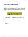
MPC System for Windows – User’s Manual
Sp. z o.o. [Ltd.]
41-250 Czeladź ul. Wojkowicka 21, Poland
Tel. (0-32) 265 70 97, 265 76 41, 763-77-77
Fax: 763-75-94
www.mikster.pl
[email protected]
(December 10, 2002)
MPC System for Windows – User’s Manual
TABLE OF CONTENTS
BASIC INFORMATION CONCERNING THE MPC SYSTEM ....................................... 3
SYSTEM DESCRIPTION ................................................................................................................. 3
FUNCTIONAL CHARACTERISTICS: ................................................................................................ 3
SYSTEM REQUIREMENTS ............................................................................................................. 3
OPERATIONS INVOLVING SYSTEM ACTIVATION..................................................... 4
CONFIGURATION OF MICROPROCESSOR CONTROLLERS ............................................................... 4
MAKING OF THE RS-485 INSTALLATION, WHICH CONNECTS CONTROLLERS WITH COMPUTER .. 4
COMPUTER INSTALLATION OF THE PROGRAM.............................................................................. 5
FIRST START OF THE APPLICATION .............................................................................................. 5
ADDING AND MODIFYING CONTROLLERS OPERATED BY THE APPLICATION ............................... 5
LIST OF AUTHORIZED PROGRAM USERS ...................................................................................... 7
ADJUSTING THE SYSTEM TO USER’S NEEDS.............................................................. 8
DIAGRAM SETTINGS .................................................................................................................... 8
Temperature axis (left) ............................................................................................................ 8
Humidity axis (right) ............................................................................................................... 9
Time axis (bottom)................................................................................................................... 9
General.................................................................................................................................... 9
Heading and footer ............................................................................................................... 10
Variables describing the process: ......................................................................................... 11
Printout settings .................................................................................................................... 11
SETTINGS RELATED TO PRODUCT IDENTIFICATION IN MANUFACTURING PROCESSES ............... 12
CHANGE OF ID CONNECTION WITH PROCESS NAME .................................................................. 14
ADMINISTERING THE MPC SYSTEM............................................................................ 15
PROGRAM SECURITY BACKUP ................................................................................................... 15
THE MPC ARCHIVE ................................................................................................................... 17
THE MPC ARCHIVE SETTINGS................................................................................................... 17
PROGRAM FEATURE SETTINGS – CONFIGURATION .................................................................... 18
CONTROLLER SETUP .................................................................................................................. 19
Window “Controller SETUP Settings”................................................................................. 20
RECORDING VERIFICATION........................................................................................................ 21
PROCESS DELETION FROM THE PROGRAM ................................................................................. 21
OPERATOR'S WORK IN THE MPC PROGRAM ........................................................... 22
PROGRAM ACTIVATION ............................................................................................................. 22
MONITORING OF EQUIPMENT (CHAMBER) OPERATION.............................................................. 23
RECORDING RECEPTION FROM CONTROLLERS........................................................................... 25
REVIEW OF MANUFACTURING PROCESSES ................................................................................ 26
CREATING THE LIST OF PROCESS NAMES .................................................................................. 28
Page 2
MPC System for Windows – User’s Manual
BASIC INFORMATION CONCERNING THE MPC SYSTEM
System Description
The System has been designed to cooperate with specialized controllers manufactured by
MIKSTER, which record and supervise manufacturing processes, among others in brewingsmoking chambers, heat boilers, drying chambers, vacuum mass devices. The MPC System is
provided with documentation compliant with HACCP.
Current version: MPC 1.08e supports the following controllers:
- MCC 050
- MCC 051
- MCC 100
- MCC 106
- MCC 2100
- MCC 3021
Functional Characteristics:
• Monitoring of current equipment state, which allows checking:
- which processes are activated in controllers;
- values of preset and read out parameters;
- which devices have been turned on by a controller
• Readout of recordings form controllers
• Review of recordings form controllers in tabular form and on diagrams
• Printouts of recordings (tabular form and diagram)
System Requirements
The MPC operates in Windows operating system on PC computers.
Any of operating system versions listed below is suitable:
Windows 95B (second edition)
Windows 98
Windows NT 4.0 SP3
Windows 2000
Minimum hardware requirements: Pentium processor, 32MB RAM, 1 free RS232 port, free
space on hard disk required for installation purposes: approximately 12MB. Recommended
minimum 100MB free space on hard disk for operation.
Page 3
MPC System for Windows – User’s Manual
OPERATIONS INVOLVING SYSTEM ACTIVATION
In order to make the MPC System operation possible, it is necessary to carry out activities
described below in proper sequence.
Configuration of Microprocessor Controllers
The controllers are provided with service manual containing description of parameters saved
in a controller SETUP. According to information from the above-mentioned service manuals,
it is necessary to preset correct transmission parameters in each controller:
• RS 485 address – where particular controller is to be visible
(each controller must have a unique number in the network, it is general practice to assign
a number consistent with common unit name, e.g. address=1 is set for chamber 1);
• transmission speed – usually the preset value is 9600
when switching to other speed values – it is recommended to set the same parameter value
for all controllers;
• transmission protocol – there are two options to select from: MIKSTER-BUS or
MODBUS, it is recommended to set MODBUS (although in some controllers the
MODBUS protocol may be unavailable).
Making of the RS-485 Installation, Which Connects Controllers with
Computer
The controllers are connected with computer through the RS485 line. It is required to have a
RS232/RS485 converter in order to make connection. The converter shall be connected to a
serial communication port of a computer, usually COM1 or COM2. Supplied converter is
equipped with a 25-pin connector. If your computer is not equipped with this COM connector,
use provided adapter plug 9/25 pins.
In order to connect controllers with a computer use a two-conductor cable in dense braided
screen. Connect wires to converter terminals marked A and B. Then connect screen to the
“Guard” terminal.
When connecting the cable, ensure that colors of wires match, that is color of wire connected
to terminal A must be the same along the entire line, and the wire connected to terminal B
must be the same along the line. All units connected to the RS-485 line shall have all
connectors marked A connected with one wire, and connectors marked B connected with the
other wire.
Comment:
9 as much as possible, wire shall be laid in sufficient distance from power cables (do not
lay it in parallel, crossing is allowed),
9 it is recommended to use screened wire 2x0.34 mm (cord),
Page 4
MPC System for Windows – User’s Manual
9 it is possible to connect to the system 32 pieces of equipment (using one COM port in
a PC computer, if there are two ports, we may use up to 64 pieces of equipment),
9 maximum wire length: 1000 m,
9 transmission line shall be earthed in one point at the end of line, it may be either
converter at the computer or a controller – do not earth the line in more than one point,
since this may result in transmission errors; at controllers screens shall be connected
with each other, but they may not be connected to a pin.
If earthed line is left at one of the controllers, then do not connect the GUARD
terminal at the RS 232/485 converter.
Computer Installation of the Program
The application has been designed to work in Windows 98, Windows 2000 and Windows NT
environment.
It is delivered on a CD-ROM (or on 4 floppy disks, 1.44MB).
On most computers installation program will be automatically activated after putting the CDROM in a drive. If not, install the application by activating SETUP. EXE program, to be
found on CD-ROM in the MPC\DISK1 folder.
After installation, the application will be available after pressing the “Start” button – located
on taskbar, then “Programs” – “Mikster” group – abbreviation: “wmpc”.
First Start of the Application
When started, the program inquires about the USER. As a default, after installation there are
two users: administrator – marked with the Adm code, and operator marked with the mpc
code (in previous versions: Oper); both users have access without password.
At the first start it is required to enter user code: Adm, do not enter password, and press OK
button. If wrong data is entered, message: “Wrong operator code or password” will be
displayed – then press the OK button, and try again to enter operator code and password,
paying attention to size of letters.
Typical actions at first start:
1. Entering the controller list (devices) operated by the application;
2. Entering the user list and attributing passwords to each of them;
3. Entering the program parameters;
4. Setting of proper diagram parameters and printout parameters;
5. Entering names of products and identifiers (IDs) corresponding with them, or entering
names and numbers of programs.
Adding and Modifying Controllers Operated by the Application
Access to the controller list is possible after having logged in with administrator rights.
In upper menu select the Controller Settings, and then Controller List items. The “Controller
List” window will appear. It contains all previously entered controllers. Here we may add a
new controller or modify settings of an already entered one.
Page 5
MPC System for Windows – User’s Manual
In order to add a new controller click with a mouse on
or press the INSERT key on the
keyboard. Window CONTROLLER SETTINGS will appear – then fill in all fields and press
the SAVE key.
Explanation of fields in the CONTROLLER SETTINGS window:
Controller name – usually the name of a device operated by the controller is entered here
e.g. CHAMBER 01
Comment:
As a result of entering only “CHAMBER 1” “CHAMBER 1” and
“CHAMBER 10” will be placed next to each other, since both start with
the same digit – if entered devices are marked with numbers including first
zeros, e.g. “01” – the sequence of displaying will be always correct.
Clear buffer after recording readout – is important in case of cooperation with controllers
using the MiksterBus protocol; typical value is YES.
Communication port – select port, to which converter RS485 has been connected,
RS 485 address – each device on the RS485 line possesses its unique address, enter adequate
address for a particular controller; range of correct values in case of the MiksterBus protocol
is from 0 to 31. When using the Modbus – correct values range from 1 to 32.
Transmission speed – typical value is 9600 b/s, selected value must match the value set in a
particular controller. It is recommended for all pieces of equipment to work with the same
speed.
Transmission protocol – typical value is MODBUS, selected value must match the value set
in a particular controller.
Controller code – it is not entered by user directly from the keyboard; after pressing the
AUTHORIZE button it shall be received from the controller; it will be saved as soon as
correct authorization code is entered.
Authorization – after having received the controller code (see above), manufacturer of the
controller provides so called authorization code.
Associate process name with – for each controller separately it is possible to select whether
process name (product name) is to be associated by program number or by ID entered in the
controller at the start of the process.
Page 6
MPC System for Windows – User’s Manual
List of Authorized Program Users
Access to the controller list is possible after having logged in with administrator rights.
In upper menu select the File, and then User List items. The “User List” window will appear.
It lists all users, who have access to the program. Here we may add a new user or modify
settings for an already entered one.
or press the INSERT key on the
In order to add a new user click with a mouse on
keyboard.
As soon as all fields are filled in, click
or press ENTER on the keyboard.
Explanation of fields in the USER LIST window:
User
Enter user code, which will be used when activating the program.
Surname, first name
User’s surname and first name.
Authorization level
There are three levels of authorization to select from: review only, operator and administrator.
The first two provide access to basic program functions. The administrator level permits to
modify controllers and program parameters.
Comment:
The program offers two authorization levels for users:
OPERATOR
- basic functions available
ADMINISTRATOR - service functions for administrator
When starting the program, window “User log in” appears. In the “User” line, first enter
“User code” attributed by the administrator, and then the password.
Default user codes, after program installation:
User
mpc
Adm
Password
(no password)
(no password)
Authorization level
operator
administrator
Comment:
Previous MPC versions did not have User: mpc, Oper was available instead.
Page 7
MPC System for Windows – User’s Manual
ADJUSTING THE SYSTEM TO USER’S NEEDS
Diagram Settings
User may adjust diagram form to his own requirements. Diagram settings window is available
from either “Process list” or “Process Diagram” windows, by pressing the Set button.
Setting name
The application is supplied with one setting named “Start Settings”.
Usually there is no need for the program to have other settings. However, if processes with
parameters varying to considerable extent are recorded in the system, frequent modifications
of settings may be necessary to view them. In such case it may be purposeful to add a new
setting to make it possible during viewing the processes to select a setting, which would be
adjusted to a particular process.
Diagram settings have been divided into the following groups:
Temperature axis (left)
Humidity axis (right)
Time axis (bottom)
General
Heading and footer
Printout settings
Select proper overlap in order to modify setting of a particular group.
Temperature axis (left)
Description
The axis may be drawn automatically or “manually”. If the Automatic option is selected, then
starting point and end point are selected automatically, depending on values contained in the
process. If the Automatic option is not marked, entered values: minimum value, maximum
value and minimum scale value remain valid.
Grid visible – as a result of selecting this option, auxiliary lines will be drawn on the diagram
from values on an axis, forming so-called grid.
Degrees Celsius constitute the unit of measure for this axis.
Page 8
MPC System for Windows – User’s Manual
Humidity axis (right)
Description
The axis may be drawn automatically or “manually”. If the Automatic option is selected, then
starting point and end point are selected automatically, depending on values contained in the
process. If the Automatic option is not marked, entered values: minimum value, maximum
value and minimum scale value remain valid.
Grid visible – as a result of selecting this option, auxiliary lines will be drawn on the diagram
from values on an axis, forming so-called grid.
Percent is the unit of measure for this axis.
Time axis (bottom)
Description
The axis may be drawn automatically or “manually”. If the Automatic option is selected, then
starting point and end point are selected automatically, depending on values contained in the
process. If the Automatic option is not marked, entered values: minimum value, maximum
value and minimum scale value remain valid.
Grid visible – as a result of selecting this option, auxiliary lines will be drawn on the diagram
from values on an axis, forming so-called grid.
Time is the unit of measure for this axis.
Time display format – determines scale resolution, it is possible to select such value from
drop-down list box, which best matches particular process. Most often it is hour:minute.
General
Description
Select in section Visible registered values, which data is to be drawn on a diagram. Usually all
three items: bar temperature, chamber temperature and humidity are marked. For each item it
is possible to set color to be used to draw particular values.
Below you will find separate section Visible preset parameters, which allows to select,
whether lines with preset parameters are to be drawn. On the diagram preset parameters are
drawn with broken line, using the same color as registered values.
Linear approximation – if this option is not selected, recording diagram will be in form of
steps, particular measured values are connected with horizontal and vertical lines. Should this
option be marked, measured values are connected with skew lines, which approximate values
between each two measurements.
Page 9
MPC System for Windows – User’s Manual
Visible stages of processes – settings of this option are important only for selected types of
controllers, e.g. for MCC-2100, MCC-3021 – in which they are programmed and used during
operation of process stage.
As a result of selecting this option, stages of processes will be visible and described on the
diagram.
Below you will find the Color of stage lines item, which allows to preset color to be used to
draw stage lines and their description.
Diagram background color – this option allows selecting diagram background color (the
setting applies only to screen and does not affect printout).
Diagram line thickness – permits to make thicker lines of recordings on a diagram (the
setting applies both to screen and printout).
Heading and footer
Description
Each printed process consists of heading, and then recorded specimens and footing. User may
adjust the appearance of printout heading and footer. The first line of heading may contain
such information as plant name, address, and department. In the second line we may put
information about the process: process serial number, product (process) name, product
identifier. Footer may contain information about process termination time and comments
concerning the process.
Heading (or footer) entered by user consists of text and so-called “variable values”. The text
will be printed precisely as it has been entered, while variable values will be replaced during
printing with values from selected process. Using variable values, we are able to determine
parameters, which we intend to have on selected process printout.
If we want controller name, program name or process (product) name to appear on the
recording report, it is necessary to use variable values (detailed information in point variables describing a process).
How to modify heading and footer
1. Open the “Process list” window
2. Press the “Settings” button
3. Window ”Diagram Settings” shall appear
4. Select the “Heading and Footer” overlap
5. Enter Heading contents in field marked Heading
6. Press the “Select Font” button in order to change font type
7. Press the “Close” button
Page 10
MPC System for Windows – User’s Manual
Example heading:
MEAT PRODUCTION PLANT "PLANT NAME"
Process: <&NUMBER>, Product name: <&PROCESS>
Activated: <&STARTPROCESS>
Example of printout for heading entered as above:
MEAT PRODUCTION PLANT "PLANT NAME"
Process: 58584, Product name: Krakowska Sausage
Activated: 2000-12-01 14:45
Variables describing the process:
The list of available variables and their explanation:
<&ID_PROCESS> - enters 8-digit product (process) identifier
<&ID_RECORDER> - controller number (id)
<&PROCESSEND> - date and hour of process termination
<&NUMBER> - process serial number
<&PROCESS> - enters product (process) name
<&PROGRAM> - controller program number
<& RECORDER> - enters name of controller, at which particular process was recorded
<&PROCESSSTART> - date and hour of process activation
<&COMMENTS> - list of comments, which were entered in the process
See also:
printout settings
heading and footer
diagram settings
Printout settings
Graphics describing data on diagram
If this option is selected, then data from recording are marked with selected graphic signs
when printing diagram.
Color print of graphic signs
If this option is selected, graphic signs will be printed in color.
Page 11
MPC System for Windows – User’s Manual
Settings Related to Product Identification in Manufacturing
Processes
Access to identification settings is possible after having logged in with administrator rights.
In upper menu select item File and then Program parameters. The “Program parameters”
window will appear. Select there the “Identification of Processes” overlap.
Explanation of fields:
ID connection with process name
Options to select interpretation of 8-digit id, which is entered in the controller during process
start-up:
- 8 digits of the id may determine 1 assortment (it is so by default), then products
shall be entered in the program with an 8-digit ID
- 8-digit id determines 2 assortments, products shall be entered in the program with a
4-digit ID
- 8-digit id may be user defined, selection of this option makes the “ID Definition”
field available. Enter in the field 8 characters specifying how digits of ID being entered
in the controller are to be interpreted by the program. Characters available:
Character
A
B
1
2
3
4
5
6
7
Explanation
- connection with names of products
- connection with names of products
- additional files – no. 1
- additional files – no. 2
- additional files – no. 3
- additional files – no. 4
- additional files – no. 5
- additional files – no. 6
- additional files – no. 7
Examples:
AAAAAAAA
Product identified by 8 digits of an ID entered will be inserted.
BBBBBBBB
Product identified by 8 digits of an ID entered will be inserted.
AAAABBBB
Two products will be inserted; each identified by 4 digits.
11AAABBB
An item from Files No. 1 identified by 2 digits and two products
identified by 3 digits will be inserted.
12AAABBB
An item from Files No. 1 identified by 1 digit, an item from
Files No. 2 also identified by 1 digit and two products identified
by 3 digits will be inserted.
Page 12
MPC System for Windows – User’s Manual
Comment:
1. Moreover, identification is related to controller settings. It is necessary to modify
controller setup to make it possible at process start to enter identifying product code in
a controller. Controller setup description is in the controller manual.
2. When changing this parameter read the: Modifying ID connection with process
name
External product id base
Usually, this option should be unmarked. When this option is selected, product names are
taken from an external database. The database parameters shall be specified in fields listed
below.
Example of filling in names of fields for an external database
ID field name:
BATCH_NUMBER
Name of field with name: BATCH _NAME
Standard for coding Polish characters: MAZOVIA Æ WINDOWS
Page 13
MPC System for Windows – User’s Manual
Change of ID Connection with Process Name
If during program operation it becomes necessary to change the ID Connection with Process
Name (detailed parameter description above), the following operations shall be carried out.
1. It is recommended to make security backup of all data prior to approaching to
introduce changes.
2. Receive recordings from controllers related to settings used so far.
3. Execute data archiving, that is data transfer from current base to the archive (for
detailed description see chapter Archive) using the following settings :
How many days with processes shall be left = 0 days
Round off to full month = NO
As a result of this operation there will be no processes in current base. They will be
available through pressing the Archive button in the main program window.
4. Execute new settings – ID connection with process name
5. Adjust files to new settings. If Product Names and Product IDs files were used – it
may be necessary to modify the ID.
6. If controllers were carrying out recordings during introducing changes, it might be
needed to recover some processes, which will be identified according to new settings.
Use the Recording Verification function for this purpose.
In case if more processes are recovered as a result of using the Recording
Verification function, that is also former processes, already transferred to the Archive,
are recovered, it is possible to delete them (see Æ Process Deletion from the
Program).
Page 14
MPC System for Windows – User’s Manual
ADMINISTERING THE MPC SYSTEM
Administrative operations shall be carried out carefully. Improper changes executed by user,
who has administrator rights, may result in data loss and erroneous system operation. Regular,
everyday work with the system shall be carried out through logging in with operator rights.
Program Security Backup
Current data collected in the MPC should be copied everyday! Making copies is aimed to
protect against data loss, caused e.g. by:
• equipment failure (hard disk damage)
• incidental data deletion by the user
• partition deletion by a virus
• database damage
Suggested methods to make copies are as follows:
• copying to other network drive
• recording on CD-ROM
• copying to a “second” computer disk inserted only for backup making purposes
The following files shall be copied:
- all files from DATA folder
- files with *.DAT and *.INI filename extensions from the program folder
The SECURITY BACKUP function is used to make copies of current data. User is able to
adjust this function.
Access to security backup settings is possible after having logged in with administrator rights.
In upper menu select the File item, and then Program Parameters. “Program Parameters”
window will appear – select the Security Backup overlap.
Explanation of fields
Security backup Folder:
enter name of the folder, in which data backup is to be created, if it does not exist – create it
“manually”
External program making security backup:
enter packing program name, or leave the field empty – in this case data will be only copied
External program parameters:
enter parameters – in compliance with an instruction for a given packing program,
Comment: - by default the program expects that name of file (or folder) with backup is the
date in year month day format – e.g. 20010311, typed without separating characters. Also, the
Page 15
MPC System for Windows – User’s Manual
above-mentioned file should be located in the security backup Folder, therefore in case if it
does not exist, the program calls the data copying program. In case if wrong parameters are
entered:
a). data will not be copied,
b). although data will be copied, program will be trying to make more backup copies on the
same day
Make data backup:
select from the list:
- “manual” backup making
- everyday when starting the program
- everyday at preset hour
Examples:
If user does not employ any external packing programs:
Security backup Folder: C:\ArchiveMPC
External program making security backup: (leave empty)
External program parameters: (leave empty)
Make data backup: everyday when starting the program
Attention: the following fields
“External program making security backup”
“ External program parameters”
- shall be left empty!
If user employs the ARJ packing program:
Security backup Folder: C:\ArchiveMPC
External program making security backup: ARJ.EXE
External program parameters: a <&BACKUP FOLDER>\<&DATA>.arj
<&DATA FOLDER>\*.* <&PROGRAM FOLDER>\*.*
Make data backup: everyday when starting the program
Page 16
MPC System for Windows – User’s Manual
The MPC Archive
It is required to store data concerning processes for the period up to 3 years. After some use
time, volume of data collected in the program will be so large, that making of e.g. security
backup may become troublesome. Access to data collected in the database becomes slower.
As a result of the above, the MPC ARCHIVE has been created in the program. User may
move processes from current database to the archive.
Access to data kept in the archive is possible from program main window. Press the
ARCHIVE [ARCHIWUM] button.
Window allowing to select archive period will appear. Press OPEN after selecting period
from the list.
While reviewing archive data there is no access to the monitor window and functions related
to introducing changes in data (recording readout, change of product names).
The MPC Archive Settings
The settings permit to adjust the MPC Archive function to user’s requirements.
Access to archive settings is possible after having logged in with administrator rights.
In upper menu select the File item, and then Program Parameters. “Program Parameters”
window will appear – select the MPC Archive overlap.
Explanation of fields in the window:
Folder, in which the archive shall be located
For example: C:\MPC Archive
Comment:
Indicated folder should exist ! Create it manually using e.g. Windows Explorer
Number of days to be left:
By default it is 180 days (6 months). Date determining, which processes will remain
among current data and which will be transferred to the archive, shall be set on the basis
of entered value “How many days to leave?” All processes older than the date set will
be transferred to the indicated folder.
Round off to full month
By default: YES
Query if to make
Select, if prior to making an archive there should appear a window with query to
confirm whether to make an MPC archive or not (by default: YES).
Page 17
MPC System for Windows – User’s Manual
Program Feature Settings – Configuration
Access to archive settings is possible after having logged in with administrator rights.
In upper menu select the File item, and then Program Parameters. “Program Parameters”
window will appear – select the Configuration overlap.
Explanation of fields:
Database rebuilding after incorrect termination of program operation
In case if the program operation is incorrectly terminated (current decay, system hang-up),
and this option has been previously selected, the program shall propose database rebuilding.
Visible button “Diagram Settings” for operator
If this option is selected, user with lower extent of rights will have access to settings related to
diagram and printout appearance.
Put shortcut in the “Autostart” group and start Monitor after having started Windows
As a result of selecting this option, after Windows is started, the program will activate and
switch without logging in to monitoring of controller work.
Page 18
MPC System for Windows – User’s Manual
Controller Setup
For each controller registered in the MPC system it is possible to prepare SETUP on a
computer, and then send it to the controller.
SETUP sending and receiving is carried out separately for each controller.
It is possible to receive current SETUP from a controller, correct it and then send it back to
the controller.
How to enter SETUP values in the program?
1. Enter the program with administrator access rights
2. In upper menu select “Controller Settings -> Controller SETUP”
3. Window “Select Device” will appear – select in it the controller, for which you intend to
modify SETUP, and then press the “Next” button
4. Window “Controller SETUP Settings” will appear
5. In the function list select the function, which value is to be modified, and press the
CORRECT button
6. There should appear a window “Function Value Editing” containing information on name
of the function being modified and allowable range. Enter correct value and press the SAVE
button
Comment:
In case of some functions the “ Function Value Editing” window appears along with a line, in
which we have to select allowable values in form of text.
7. Enter correct values in the SETUP, repeating steps no. 5 and 6
How to receive SETUP from controller?
1. Enter the program with administrator access rights
2. In upper menu select “Controller Settings -> Controller SETUP”
3. Window “Select Device” will appear – select in it the controller, for which you intend to
modify SETUP, and then press the “Next” button
4. Window “Controller SETUP Settings” will appear
5. In order to receive current SETUP of a controller press the “Read” button, as a result the
computer will try to communicate with the controller. If the try is successful, there will appear
window containing an information that SETUP has been read, then function list will be
updated – current values will appear
How to send SETUP to controller?
1. Enter the program with administrator access rights
2. In upper menu select “Controller Settings -> Controller SETUP”
3. Window “Select Device” will appear – select in it the controller, for which you intend to
modify SETUP, and then press the “Next” button
4. Window “Controller SETUP Settings” will appear
5. In order to send current SETUP of a controller press the “Send” button”. There should
appear a window demanding confirmation and if we respond YES, the computer will try to
Page 19
MPC System for Windows – User’s Manual
communicate with the controller. If the try is successful, there will appear window containing
an information that SETUP has been correctly sent to the controller.
Window “Controller SETUP Settings”
This window contains the following elements:
• a line with selected controller, for which SETUP is to be modified, sent or received
• below: a line with information concerning controller type (e.g. MCC-2100)
• then SETUP modification date and date of sending SETUP to the controller
• then list of setup functions, consisting of the following columns:
- function number,
- function name,
- function value
Number of items depends on controller type!
• buttons are located on window right side in the following order:
CLOSE – closes the setup window
CORRECT – corrects selected SETUP item
READ – reads SETUP of selected controller
SEND – sends SETUP to selected controller
COMPARE – compares selected SETUP with that stored in the controller
memory
Example operation of controller setup using the MPC program
If we intend to introduce minor modification in a controller setup, it is not recommended to
enter all values “manually”, it is best to use current setup stored in the controller memory,
modify it and then send to the controller.
Order of operations:
1). Receiving SETUP from the controller
2). Modifying SETUP value in the program
3). Sending SETUP to the controller
Page 20
MPC System for Windows – User’s Manual
Recording Verification
Recordings are downloaded from controllers through temporary files (LOG type).
On the basis of these files it is possible to restore processes in the program. I order to do that
we must use the “Recording Verification” function, which is available for program
administrator.
In upper menu select the File item, and then Recording Verification. Window “MPC
Recording Verification” will appear.
After filling in time range field and selecting controller press the Execute button – the
program will ask for confirmation. As soon as button YES is selected, recording verification
will begin.
Comments
If entire process is missing in the program, it will be added. If process end is missing, it will
be found and completed. Missing samples shall not be added to processes in case if they are
newer than those already entered, that is if there exists a process with missing initial
measurements, it is necessary to remove the entire process, and then use the recording
verification.
Process Deletion from the Program
Administrator is able to delete process from the program.
First open the ”Process list” window and then press the key board function key “F10” – as a
result the “Delete Process” button will appear. As soon as it is pressed, the program will ask
to confirm selected process deletion. After confirmation the process will be deleted.
Press the F10 key to hide the “Delete Process” button.
Page 21
MPC System for Windows – User’s Manual
OPERATOR'S WORK IN THE MPC PROGRAM
Program Activation
In order to activate the program on a taskbar press the “Start” button, and then: “Programs” –
“Mikster” group – “wmpc” shortcut. Window “User log in” will appear – enter your own user
code and password and press the OK button.
Comment: in case if administrator has introduced no modifications, default operator code is
mpc (in previous program versions - Oper), do not fill in the password field.
The main program window will appear. It contains the following buttons:
• PROCESSES (PROCESY)
Opens the list of processes read out from controllers
• READOUT (ODCZYT)
controllers
Permits “manual” readout of recordings from selected
• MONITOR
controllers
Opens preview with information on current state of
• NAMES (NAZWY)
Opens window containing IDs of products and process
names or window with numbers of programs and process names
• ARCHIVES (ARCHIWUM)
archival data
Permits to browse through successive periods of
Page 22
MPC System for Windows – User’s Manual
Monitoring of Equipment (Chamber) Operation
Press the MONITOR button in program main menu – window “Equipment State Monitor”
will appear. The window contains preview of first 16 units (controllers).
Basic information will be displayed:
• Unit name,
• Running program (or STOP information)
• Cycle number
• Information concerning current product
If the program operates more than 16 controllers, it is possible to switch from one controller
to another controllers, using the following buttons:
Arrow up and arrow down,
Number of currently displayed page is shown between arrows. At this moment it is
possible to display up to 8 pages, 16 controllers on each.
In order to obtain detailed information on current state of a unit, use mouse to select a
controller and click on it with left mouse button.
As a result window containing current information will appear. Available information
depends on controller type. Window for MCC-1000-type controllers will look different than
e.g. window for MCC 3021 type.
Displayed information:
• Unit name,
Page 23
MPC System for Windows – User’s Manual
•
•
•
•
•
•
•
•
Date and clock time in the controller,
Controller program version,
Running program (or STOP information)
Cycle number (Cycle name)
Information concerning current product
Preset process parameters
Currently measured parameters
State of equipment switching on / off executed by the controller
The illustration above applies to the MCC-3021 controller
Page 24
MPC System for Windows – User’s Manual
Recording Reception from Controllers
There are two options to receive recordings from controllers.
First option
In case of all controllers, it is always possible to receive any recording by pressing the
READOUT button in program main window. The “Recording Readout” window will
appear.
Select one controller (or all), from which recordings are to be received and press the START
button.
Received recordings are saved in database. As soon as the operation is complete, the
“Recording Readout” window will be closed, active.
Second option
In case of controllers using the MODBUS protocol recordings are received automatically in
the “Equipment State Monitor” window. Recording is received with some delay, while the
controller is in operation. If current controller state is STOP, all previously not received
recordings will be downloaded.
Page 25
MPC System for Windows – User’s Manual
Review of Manufacturing Processes
It is possible to activate process review from program main window by pressing the
PROCESSES button. As a result there will appear the “Process List” window containing the
list of processes, which were registered in the program.
Recorded
processes
Preset and recorded
parameters for
process selected
above
The Controller field contains the list of controllers to select from. Preset default value “All”
results in showing processes from all controllers. In case of selecting e.g. “CHAMBER 01”
only processes from “CHAMBER 01” will be displayed.
Explanation of buttons:
DIAGRAM
Opens the “Process Diagram” window, in which a diagram of selected process will be
drawn. User may alter the diagram appearance.
FILTER
Using the filter it is possible to restrain the list of displayed processes. Press the FILTER
button in order to do this. As a result, there will appear the “Filter the Process List”, in which
we may define time range, program and product ID. Processes meeting entered criteria will be
displayed after pressing the “Filter” button. When the filter is activated, displayed process
list will have yellow background. In order to switch the filter off, press the “Filter” button
again and press “Switch off Filter” in the “Filter the Process List” window.
SETTINGS
Opens the “Diagram Settings” window. By default only administrator has right to modify
diagram settings after installation.
Page 26
MPC System for Windows – User’s Manual
COMMENTS
When this button is pressed, a window will open, in which it is possible to enter comments
regarding the process.
PRINT
Permits to print selected fragment or entire process in tabular form.
DEFAULT
Returns the default appearance of the process list window.
Page 27
MPC System for Windows – User’s Manual
Creating the List of Process Names
In order to define product name in processes registered by the program, we may use the
identifier entered in controllers at process start or controller program number used in the
process.
Depending on selected identification method (identifier or program number), it is required to
fill in the following list:
• Process names and product ids
or
• Process names and program numbers
In order to fill in the list of process names press the NAMES button in program main menu.
There will appear a window allowing selection of list type: ”process names and product ids”
or „process names and program numbers”. When selection is made, window „List of Process
Names” will open – enter here the list of products, which are to be identified.
Page 28