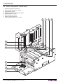
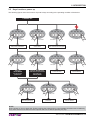
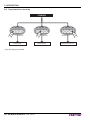
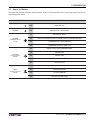
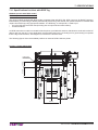
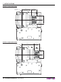
1
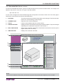
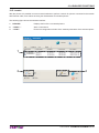
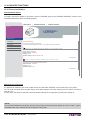
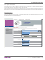
OEM
USER MANUAL
KPM302
KPM303
Commands manual
77200000030600
CUSTOM ENGINEERING S.p.A.
Str. Berettine 2
43010 Fontevivo (PARMA) - Italy
Tel. : +39 0521-680111
Fax : +39 0521-610701
http: www.custom.biz
Customer Service Department:
Email : [email protected]
© 2012 CUSTOM ENGINEERING S.p.A. –
Italy. All rights reserved. Total or partial reproduction of this manual in whatever form,
whether by printed or electronic means, is
forbidden. While guaranteeing that the information contained in it has been carefully
checked, CUSTOM ENGINEERING S.p.A.
and other entities utilized in the realization
of this manual bear no responsibility for
how the manual is used.
Information regarding any errors found in it
or suggestions on how it could be improved
are appreciated. Since products are subject to continuous check and improvement,
CUSTOM ENGINEERING S.p.A. reserves
the right to make changes in information
contained in this manual without prior
notification.
The pre-installed multimedia contents
are protected from Copyright CUSTOM
ENGINEERING S.p.A. Other company
and product names mentioned herein
may be trademarks of their respective
companies. Mention of third-party products
is for informational purposes only and
constitutes neither an endorsement nor a
recommendation. CUSTOM ENGINEERING S.p.A. assumes no responsibility with
regard to the performance or use of these
products.
THE IMAGES USED IN THIS MAN-
GENERAL SAFETY INFORMATION
Your attention is drawn to the following
actions that could compromise the characteristics of the product:
• Read and retain the instructions which
follow.
• Follow all indications and instructions
given on the device.
• Make sure that the surface on which
the device rests is stable. If it is not, the
device could fall, seriously damaging it.
• Make sure that the device rests on a hard
(non-padded) surface and that there is
sufficient ventilation.
• When positioning the device, make sure
cables do not get damaged.
• Use the type of electrical power supply
indicated on the device label. If uncertain, contact your dealer.
• Make sure the electrical system that
supplies power to the device is equipped
with a ground wire and is protected by a
differential switch.
• Do not block the ventilation openings.
• Do not insert objects inside the device as
this could cause short-circuiting or damage components that could jeopardize
printer functioning.
• Do not carry out repairs on the device
yourself, except for the normal maintenance operations given in the user
manual.
• Make sure that there is an easily-accessible outlet with a capacity of no less than
15A in the vicinity of where the device is
to be installed.
• Periodically perform scheduled maintenance on the device to avoid dirt build-up
that could compromise the correct, safe
operation of the unit.
• Before any type of work is done on the
machine, disconnect the power supply.
• Do not touch the head heating line with
bare hands or metal objects. Do not
perform any operation inside the printer
immediately after printing because the
head and motor tend to become very
hot.
UAL ARE USED AS AN ILLUSTRATIVE EXAMPLES. THEY COULDN’T
REPRODUCE THE DESCRIBED
MODEL FAITHFULLY.
UNLESS OTHERWISE SPECIFIED,
THE INFORMATION GIVEN IN THIS
MANUAL
ARE REFERRED TO ALL MODELS
IN PRODUCTION AT THE ISSUE
DATE OF THIS DOCUMENT.
GENERAL INSTRUCTIONS
CUSTOM ENGINEERING S.p.A. declines
all responsibility for accidents or damage
to persons or property occurring as a result of tampering, structural or functional
modifications, unsuitable or incorrect installations, environments not in keeping
with the equipment’s protection degree or
with the required temperature and humidity
conditions, failure to carry out maintenance
and periodical inspections and poor repair
work.
THE CE MARK AFFIXED TO
THE PRODUCT CERTIFY
THAT THE PRODUCT SATISFIES THE BASIC SAFETY
REQUIREMENTS.
The device is in conformity with the essential Electromagnetic Compatibility and
Electric Safety requirements laid down in
Directives 2006/95/CE and 2004/108/CE
inasmuch as it was designed in conformity
with the provisions laid down in the following Standards:
• EN 55022 Class B (Limits and methods
of measurements of radio disturbance
characteristics of Information Technology Equipment)
• EN 55024 (Information Technology
Equipment – Immunity characteristics –
Limits and methods of measurement)
• EN 60950-1 (Safety of information
equipment including electrical business
equipment)
GUIDELINES FOR
THE DISPOSAL OF
THE PRODUCT
The crossed-out rubbish bin logo means
that used electrical and electronic products
shall NOT be mixed with unsorted municipal waste. For more detailed information
about recycling of this product, refer to the
instructions of your country for the disposal
of these products.
• Do not dispose of this equipment as
miscellaneous solid municipal waste, but
arrange to have it collected separately.
• The re-use or correct recycling of the
electronic and electrical equipment
(EEE) is important in order to protect
the environment and the wellbeing of
humans.
• In accordance with European Directive
WEEE 2002/96/EC, special collection
points are available to which to deliver
waste electrical and electronic equipment and the equipment can also be
handed over to a distributor at the moment of purchasing a new equivalent
type.
• The public administration and producers
of electrical and electronic equipment
are involved in facilitating the processes
of the re-use and recovery of waste electrical and electronic equipment through
the organisation of collection activities
and the use of appropriate planning arrangements.
• Unauthorised disposal of waste electrical
and electronic equipment is punishable
by law with the appropriate penalties.
The format used for this manual improves use of natural resources reducing the quantity of necessary paper to print this
copy.
POWER SUPPLY INFORMATION
The device is fed by a SELV power supply
(Safety Extra Low Voltage).
When power supply unit is installed as accessory in the end-product, the following
items must be considered:
• The power supply must be properly
bonded to the main protective earthing
termination.
• A suitable mechanical, electrical and fire
enclosure must be provided.
• The power supply has been evaluated
for use in a pollution degree 2 environment, overvoltage category II.
• An appropriate disconnect device must
be provided.
• The power supply must be installed in
compliance with the mounting, creepage, clearance, markings and segregation requirements of the end-use
application.
CAUTION: PRESENCE OF A LITHIUM
BATTERY
Risk of explosion if battery is replaced with
an incorrect type. Dispose of used batteries
according to the instructions.
WARNING: PRESENCE OF DANGEROUS VOLTAGES (POWER SUPPLY)
Risk of electric shock (accessory power
supply).
WARNING: PRESENCE OF HAZARDOUS MOVING PARTS
INDEX
INDEX
1 INTRODUCTION .................................................................................................................................................... 7
1.1 Document structure ...................................................................................................................................... 7
1.2 Explanatory notes used in this manual ........................................................................................................ 7
2 DESCRIPTION ....................................................................................................................................................... 9
2.1 Unpacking the device ................................................................................................................................... 9
2.2 Device components: external views ........................................................................................................... 11
2.3 Device components: side views ................................................................................................................. 17
2.4 Device components: internal views ............................................................................................................ 18
2.5 Keys functions: power up ........................................................................................................................... 19
2.6 Keys functions: stand by ............................................................................................................................ 20
2.7 Status led flashes ....................................................................................................................................... 21
2.8 Triple feeder led flashes ............................................................................................................................. 22
3 INSTALLATION.................................................................................................................................................... 23
3.1 Fixing brackets ........................................................................................................................................... 23
3.2 “BURSTER” configuration .......................................................................................................................... 27
3.3 “CUT AND DROP” configuration ................................................................................................................ 30
3.4 Connections ............................................................................................................................................... 34
3.5 Pinout ......................................................................................................................................................... 35
3.6 Driver.......................................................................................................................................................... 38
4 OPERATION ........................................................................................................................................................ 39
4.1 Adjusting paper width ................................................................................................................................. 39
4.2 Adjusting notch sensors position................................................................................................................ 40
4.3 Turning on the device ................................................................................................................................. 43
4.4 Paper insertion ........................................................................................................................................... 44
5 CONFIGURATION ............................................................................................................................................... 49
5.1 Configuration mode .................................................................................................................................... 49
5.2 Setup report ............................................................................................................................................... 51
5.3 Printer status .............................................................................................................................................. 52
5.4 Printer parameters ..................................................................................................................................... 53
5.5 Ethernet parameters .................................................................................................................................. 57
5.6 Hexadecimal dump .................................................................................................................................... 58
5.7 Calendar clock ........................................................................................................................................... 59
6 MAINTENANCE ................................................................................................................................................... 61
6.1 Printer paper jam........................................................................................................................................ 61
6.2 Triple feeder paper jam .............................................................................................................................. 64
6.3 Planning of cleaning operations ................................................................................................................. 65
6.4 Cleaning ..................................................................................................................................................... 66
6.5 Upgrade firmware....................................................................................................................................... 74
7 SPECIFICATIONS................................................................................................................................................ 76
7.1 Hardware specifications ............................................................................................................................. 76
7.2 Character specifications in ESC/POS™ emulation .................................................................................... 79
7.3 Specifications for RFID reader/writer ......................................................................................................... 80
7.4 Specification for reader of one-dimensional barcode ................................................................................. 80
7.5 Printer dimensions ..................................................................................................................................... 81
7.6 Power supply dimensions cod.963GE020000004 (optional) .................................................................... 90
7.7 Specifications for ticket with barcode ........................................................................................................ 91
7.8 Specifications for ticket with black mark..................................................................................................... 92
7.9 Specifications for ticket with labels............................................................................................................. 93
7.10 Specifications for ticket with hole ............................................................................................................... 93
User manual
KPM302-KPM303 5
INDEX
7.11 Specifications for ticket with RFID Tag ....................................................................................................... 95
7.12 Character sets in ESC/POS™ emulation ................................................................................................... 98
7.13 Character sets in SVELTA emulation ....................................................................................................... 105
8 CONSUMABLES ............................................................................................................................................... 107
9 ACCESSORIES ................................................................................................................................................. 109
9.1 Paper roll holder ........................................................................................................................................111
9.2 Adapter cable for power supply................................................................................................................ 115
9.3 Wirings kit with near paper end sensors (for models with triple feeder)................................................... 115
10 ALIGNMENT ...................................................................................................................................................... 117
10.1 Enable alignment ..................................................................................................................................... 118
10.2 Calibration ................................................................................................................................................ 121
10.3 Alignment parameters .............................................................................................................................. 123
10.4 Printing area ............................................................................................................................................. 127
11 TECHNICAL SERVICE ...................................................................................................................................... 129
12 ADVANCED FUNCTIONS ................................................................................................................................. 131
12.1 File sharing............................................................................................................................................... 131
12.2 Embedded Web Server ............................................................................................................................ 132
12.3 Embedded Web Server: access ............................................................................................................... 133
12.4 Embedded Web Server: functions ........................................................................................................... 135
12.5 Locator ..................................................................................................................................................... 137
12.6 Drivers installation .................................................................................................................................... 138
12.7 Logos management ................................................................................................................................. 139
12.8 Fonts management .................................................................................................................................. 141
12.9 Setup ........................................................................................................................................................ 143
6 KPM302-KPM303
User manual
1. INTRODUCTION
1
INTRODUCTION
1.1 Document structure
This document includes the following chapters:
1
2
3
4
5
6
7
8
9
10
11
12
INTRODUCTION
DESCRIPTION
INSTALLATION
OPERATION
CONFIGURATION
MAINTENANCE
SPECIFICATION
CONSUMABLES
ACCESSORIES
ALIGNMENT
TECHNICAL SERVICE
ADVANCED FUNCTIONS
information about this document
general description of device
information required for a correct installation of the device
information required to make the device operative
description of the configuration parameters of the device
information for a correct periodic maintenance
technical specification for the device and its accessories
description and installation of the available consumables for the device
description and installation of the available accessories for the device
information required for managing the paper alignment
information required for contacting the technical service
information about special functions available with the device
1.2 Explanatory notes used in this manual
NOTE:
Gives important information or suggestions relative to the use of the printer.
ATTENTION:
Gives information that must be carefully followed to guard against damaging the
printer.
DANGER:
Gives information that must be carefully followed to guard against operator injury
or damage.
User manual
KPM302-KPM303 7
1. INTRODUCTION
8 KPM302-KPM303
User manual
2. DESCRIPTION
2
DESCRIPTION
2.1 Unpacking the device
Remove the printer from its carton being careful not to damage the packing material so that it may be re-used if the
printer is to be transported in the future.
Make sure that all the components illustrated below are present and that there are no signs of damage. If there are,
contact Customer Service.
KPM302, KPM303
1.
2.
3.
4.
5.
6.
7.
8.
9.
10.
1
2
3
4
5
6
1
11.
12.
Installation instructions sheet
Upper packing frame
Power supply cable
Spacer (only for standard model)
Additional fixing brackets
Ruler
“CUT AND DROP” configuration kit (only for standard
model)
Printer
Lower packing frame
“BURSTER” configuration kit
(only for standard model)
Lower tray
Box
2
3
A
FIS LLIN
SO EA
A
RE
PA LIGN
AL
PE
GU
R G TO T
IDA
UID HE
CA
E FIX
RT
ED
A
4
5
6
7
8
W
MO ARN
VIN ING
GP !
AR
TS
7
8
9
10
11
12
User manual
KPM302-KPM303 9
2. DESCRIPTION
KPM302 (models with triple feeder)
1
A
FIS LLIN
SO EA
A
RE
PA LIGN
AL
PE
GU
R G TO T
IDA
UID HE
CA
E FIX
RTA
ED
3
4
5
6
7
8
3
2
2
1
1. Installation instructions
sheet
2. Ruler
3. “CUT AND DROP” configuration kit (only for standard
model)
4. “BURSTER” configuration
kit (only for standard model)
5. Power supply cable
6. Printer
7. Lower packing frame
8. Box
W
MO ARN
VIN ING
GP !
AR
TS
4
5
6
7
8
•
•
•
•
Open the printer packaging
Remove the upper packing frame content and remove the upper packing frame.
Take out the printer.
Keep the box, trays and packing materials in the event the printer must be transported/shipped in the future.
10 KPM302-KPM303
User manual
2. DESCRIPTION
2.2 Device components: external views
KPM302, KPM303 (standard models)
1. Printing head group
7. Status led
2. Release lever
8. Paper input
3. LINE FEED key
9. Cutter cover
4. FORM FEED key
10. Paper outfeed
5. S1 key
11. External near paper end sensor connector
6. S2 key
12. Printer chassis
1
2
3
4
5
6
7
8
12
11
10
9
User manual
KPM302-KPM303 11
2. DESCRIPTION
KPM302, KPM303 (models with ejector)
1. Printing head group
7. Status led
2. Release lever
8. Paper input
3. LINE FEED key
9. Cutter cover with ejector group
4. FORM FEED key
10. Paper outfeed
5. S1 key
11. External near paper end sensor connector
6. S2 key
12. Printer chassis
1
2
3
4
12
11
10
9
12 KPM302-KPM303
User manual
5
6
7
8
2. DESCRIPTION
KPM302, KPM303 (models with selector)
1. Printing head group
8. Paper input
2. Release lever
9. Cutter cover with selector group
3. LINE FEED key
10. Tilting slide
4. FORM FEED key
11. Sensor for tilting slide position
5. S1 key
12. Paper outfeed
6. S2 key
13. External near paper end sensor connector
7. Status led
14. Printer chassis
1
2
3
4
5
6
7
8
14
13
12
11
10
9
User manual
KPM302-KPM303 13
2. DESCRIPTION
KPM302 (standard models with triple feeder)
1. Printer chassis
9. Triple feeder
2. Printing head group
10. Paper input feeder 1
3. Release lever
11. Paper input feeder 2
4. LINE FEED key
12. Paper input feeder 3
5. FORM FEED key
13. Triple feeder led (green)
6. S1 key
14. Triple feeder led (red)
7. S2 key
15. Paper outfeed
8. Status led
16. Cutter cover
1
16 15
14 KPM302-KPM303
2
3
14
User manual
4
13
5
6
7
8
9
10 11 12
2. DESCRIPTION
KPM302 (models with triple feeder and ejector)
1. Printer chassis
9. Triple feeder
2. Printing head group
10. Paper input feeder 1
3. Release lever
11. Paper input feeder 2
4. LINE FEED key
12. Paper input feeder 3
5. FORM FEED key
13. Triple feeder led (green)
6. S1 key
14. Triple feeder led (red)
7. S2 key
15. Paper outfeed
8. Status led
16. Cutter cover with ejector group
1
16 15
2
3
14
4
5
6
7
8
9
10 11 12
13
User manual
KPM302-KPM303 15
2. DESCRIPTION
KPM302 (models with triple feeder and selector)
1. Printer chassis
10. Paper input feeder 1
2. Printing head group
11. Paper input feeder 2
3. Release lever
12. Paper input feeder 3
4. LINE FEED key
13. Triple feeder led (green)
5. FORM FEED key
14. Triple feeder led (red)
6. S1 key
15. Paper outfeed
7. S2 key
16. Tilting slide
8. Status led
17. Sensor for tilting slide position
9. Triple feeder
18. Cutter cover with selector group
1
18 17 16
15
16 KPM302-KPM303
2
3
14
User manual
4
13
5
6
7
8
9
10 11 12
2. DESCRIPTION
2.3 Device components: side views
KPM302, KPM303
1.
2.
3.
4.
5.
USB connector
RS232 connector
ETHERNET connector
SD/MMC card
Power Supply connector
1
2
3
4
5
3
4
KPM302 (models with triple feeder)
1.
2.
3.
4.
5.
6.
Cover for triple feeder connectors
USB connector
RS232 connector
ETHERNET connector
SD/MMC card
Power Supply connector
1
2
5
User manual
6
KPM302-KPM303 17
2. DESCRIPTION
2.4 Device components: internal views
1.
2.
3.
4.
5.
6.
7.
8.
Sensors for paper out presence
Opening/closing front cover sensor
Cutter position sensor
Unlocking button for mobile paper guide
Mobile sensors for notch
Head temperature sensor
Sensor of paper presence
Opening/closing printer cover sensor
7
6
5
4
3
2
1
1
18 KPM302-KPM303
User manual
7
5
8
2. DESCRIPTION
2.5 Keys functions: power up
The following figures show the functions of printer’s keys according to the operating condition of the device.
POWER UP
LF
FF
S1
S2
LF
FF
Hold down
FF
S1
S2
LF
Hold down
print the SETUP report
with printer parameters
LF
S1
LF
Fast push
FF
S1
LF
S2
FF
S1
S2
Fast push
modify
selected parameter
LF
FF
S1
S2
Fast push
LF
FF
S1
S2
LF
FF
S1
S2
Fast push
enter the
CLOCK SETUP
print the SETUP report
with Ethernet parameters
and enter the
SETUP MODE
LF
S2
initialize the notch sensor
and characterizes the paper
Fast push
enter the
SETUP MODE
for the printer
parameters
S1
Hold down
perform the
FONT TEST
S2
FF
FF
S1
S2
Fast push
skip the
SETUP MODE
LF
FF
S1
S2
Fast push
next
parameter
exit the
SETUP MODE
NOTE:
During power-up, do not press the S2 key because the printer enter in a test modality that becomes unusable by
keys; if this event occurs then turn off the printer and turn on without pressing any key.
User manual
KPM302-KPM303 19
2. DESCRIPTION
2.6 Keys functions: stand by
STANDBY
LF
FF
S1
S2
LF
Fast push
S1
S2
Fast push
advance the paper
(manual feed)
advance the paper
(preset length)
* Only with alignment enabled.
20 KPM302-KPM303
FF
User manual
LF
FF
S1
S2
Fast push
perform the ticket
alignment and the cut *
2. DESCRIPTION
2.7 Status led flashes
The Status led indicates hardware status of device. Given in the table below are the various led signals and the corresponding printer status.
STATUS LED
DESCRIPTION
-
OFF
PRINTER OFF
GREEN
ON
PRINTER ON : NO ERROR
1x
RECEIVING DATA
GREEN
2x
RECEIPT ERRORS (PARITY, FRAME ERROR, OVERRUN ERROR)
COMMUNICATION
STATUS
3x
COMMAND NOT RECOGNIZED
4x
COMMAND RECEIPT TIME OUT
2x
PRINT HEAD OVER TEMPERATURE
3x
PAPER END
4x
PAPER JAM
5x
POWER SUPPLY VOLTAGE INCORRECT
6x
COVER OPEN
3x
RAM ERROR
RED
4x
EEPROM ERROR
UNRECOVERABLE
ERROR
5x
CUTTER ERROR
6x
CUTTER COVER OPEN
YELLOW
RECOVERABLE
ERROR
User manual
KPM302-KPM303 21
2. DESCRIPTION
2.8 Triple feeder led flashes
KPM302 (models with triple feeder)
The led panel of triple feeder is comprised of two led (one of green colour and one of red colour) for each of the three
paper input feeder.
The led indicate the triple feeder status and the paper status. Given in the table below are the various led signals and
the corresponding triple feeder status.
STATUS LED
DESCRIPTION
OFF
PAPER PRESENCE
ON
NEAR PAPER END
OFF
NO PAPER OR PAPER IN PARKING SPACE (1)
ON
PAPER LOADED
slow
PAPER END DURING PRINTING
fast
PAPER JAM
RED
PAPER END
WARNING
GREEN
TRIPLE FEEDER
STATUS
NOTE:
(1)
: The paper is in “parking space” when it is present on the entrance of feeder but it is not loaded into the printer.
22 KPM302-KPM303
User manual
3. INSTALLATION
3
INSTALLATION
3.1 Fixing brackets
KPM302 (models without triple feeder), KPM303
The printer includes a kit for the assembly of two additional fixing brackets (see following figure).
The kit contains:
1. Two fixing brackets;
2. No.4 fixing screws.
1
1
2
Assembly instructions
Fix the brackets to the printer as shown in the following figures.
1
2
User manual
KPM302-KPM303 23
3. INSTALLATION
The following figure shows the printer overall dimensions with the two additional brackets (dimensions in mm).
31
150
10
45
150,1
5 - N°4 Slots
110
162,1
55
M4 - N°4 holes
10
127
85
200,24
42,5
4,7
1,5
86,5
123
2,5
191
16,5
50,9
24 KPM302-KPM303
114,3
User manual
129
16,5
3. INSTALLATION
The following figure shows the overall dimensions of the printer with the “CUT AND DROP” configuration and the two
additional brackets (dimensions in mm).
31
150
10
45
150,1
5 - N°4 Slots
110
162,1
55
M4 - N°4 holes
10
127
85
200,2
42,5
4,7
1,5
90,4
123
10,1
191
16,5
50,9
129
16,5
114,3
User manual
KPM302-KPM303 25
3. INSTALLATION
The following figure shows the overall dimensions of the printer with the “BURSTER” configuration and the two additional brackets (dimensions in mm).
31
150
10
45
150,1
5 - N°4 Slots
110
162,1
55
M4 - N°4 holes
10
127
200,2
191
4,7
42,5
1,5
86,5
123
2,5
4,5
85
50,9
26 KPM302-KPM303
114,3
User manual
16,5
129
16,5
3. INSTALLATION
3.2 “BURSTER” configuration
KPM302 (standard models and models with triple feeder)
KPM303 (standard models)
Printer is provided with a kit for the “BURSTER” configuration (see the following figure).
The kit contains:
1. Upper paper out feed mouth.
1
For the assembly procedure, proceed as follows:
1
Open the printer cover.
User manual
KPM302-KPM303 27
3. INSTALLATION
2
Unscrew the two fixing screws and take off the upper paper mouth group of the “STANDARD” configuration.
Unscrew the central fixing screw and divide the paper mouth from the light guide.
3
Unscrew the fixing pins and take off the fixed blade and the spring.
28 KPM302-KPM303
User manual
3. INSTALLATION
4
Fix the light guide with the upper paper mouth of the “BURSTER” configuration
using the screw previously removed.
5
Fix the upper paper mouth group for the “BURSTER” configuration
using the screws previously removed.
User manual
KPM302-KPM303 29
3. INSTALLATION
3.3 “CUT AND DROP” configuration
KPM302 (standard models and models with triple feeder)
KPM303 (standard models)
Printer is provided with a kit for the “CUT AND DROP” configuration (see following figure). The kit contains:
1. Label.
2. Upper paper out feed mouth.
W
MO ARN
VIN ING
GP !
AR
1
TS
For the assembly procedure, proceed as follows:
1
Open the printer cover.
30 KPM302-KPM303
User manual
2
3. INSTALLATION
2
Unscrew the two fixing screws and
take off the upper paper mouth group of the “STANDARD” configuration.
3
Using a clamp, remove the precut sheet metal on the printer cover.
User manual
KPM302-KPM303 31
3. INSTALLATION
4
Fix the upper paper mouth group for the “STANDARD” configuration
in the upper holes on the printer cover using the screws previously removed.
5
Unscrew the two fixing screws on the cutter cover and
take off the lower paper mouth of the “STANDARD” configuration.
32 KPM302-KPM303
User manual
3. INSTALLATION
6
Fix the lower paper mouth for the “CUT AND DROP” configuration
by using the screws previously removed.
7
W
MO ARN
VIN ING
GP !
AR
TS
W
MO ARN
VIN ING
GP !
AR
TS
Close the printer cover and
paste the label (supplied with the kit) on the cutter cover.
User manual
KPM302-KPM303 33
3. INSTALLATION
3.4 Connections
RS232
PC
Power Supply cable
(supplied)
ETHERNET CrossOver
standard cable
Serial standard cable
USB standard cable
USB
ETHERNET UTP
standard cable (pin-to-pin)
The following figures show the possible connections for device.
HUB
POWER SUPPLY
WARNING:
In some using conditions, we recommend the installation of a ferrite core on the power supply cable.
34 KPM302-KPM303
User manual
3. INSTALLATION
3.5 Pinout
6
4
3
1
POWER SUPPLY
Male Molex connector vertical (no. 39-30-0060)
1 +24 Vdc
2 +24 Vdc
3 +24 Vdc
J26
4 GND
5 GND
6 GND
ATTENTION:
Respect power supply polarity.
Note: Power supply cable
The following figure shows the connector pinout of the power supply cable for the device:
Female connector
Molex (n.39-01-2065)
4
1
Power supply cable
2
6
3
PIN
Cable color
Signal
1
Red
+24V
2
not connected
+24V
3
Red
+24V
4
Black
GND
5
not connected
GND
6
Black
GND
1
USB INTERFACE
Female USB type B connector
3
4
1 USB-VBUS
J13
(out)
2 PD -0
3 PD +0
4 GND
User manual
KPM302-KPM303 35
3. INSTALLATION
5
9
1
6
RS232 SERIAL INTERFACE
Female DB9 connector
1 DTR
2 TX
During transmission, takes the values “0” and “1” depending on data.
3 RX
During reception, takes the values “0” and “1” depending on data.
4 n.c.
J1
5 GND
6 DTR
When “1”, printer is power on.
7 CTS
8 RTS
When “1”, printer is ready to receive data
9 n.c.
Note: Given the presence of the RS232 standard, logic value “0” corresponds to a voltage level of between +3Vdc
and +15Vdc and logic value “1” corresponds to a voltage level of between -3Vdc and -15Vdc.
1
2
3
4
5
6
7
8
9
DEVICE
DCD
RXD
TXD
SIGNAL GND
DSR
CTS
1
2
3
4
5
6
7
8
9
DB9
DB9
Note: KPM302-KPM303 > PC connection
The following pictures shows an example of connections between the printer and a personal computer using a 9
pin female RS232 serial connectors:
PC
Note: When use a serial cable, we recommend the installation of a ferrite core on the power supply cable.
36 KPM302-KPM303
User manual
3. INSTALLATION
ETHERNET INTERFACE
1
8
Female RJ45 connector
1 TPOUT +
2 TPOUT 3 TPIN +
4 GND
5 GND
6 TPIN J16
7 n.c
8 n.c
9 +3.3 V
10 LED-LAN
11 +3.3 V
12 LED-LNK
13 Shield
14 Shield
Note:
The functionality of two led are specified in the following table:
LED
FUNCTION
LED-LNK Link (yellow color): the led lights up when a connection is active
LED-LAN Rx/Tx: (green color): the led lights up when occurs a data reception or transmission
• To directly connect the printer to a Personal Computer, use a Cross-Over Ethernet cable.
• To connect the printer to a hub device, use an UTP Ethernet cable (Pin to Pin).
Note: The pinout shown in table represents the input signals to component J15 before the isolation voltage transformer (through-hole pin).
User manual
KPM302-KPM303 37
3. INSTALLATION
3.6 Driver
The drivers are available for the following operating system:
OPERATING
SYSTEM
DRIVER
INSTALLATION PROCEDURE
Windows XP
Windows VISTA (32/64bit)
Windows
Windows 7 (32/64bit)
From the START menu, press Enter and
key-in the path where the SW was saved on your PC,
then click OK. Follow the instructions
that appear on the screen to install the driver.
OPOS (only for KPM302)
Follow the instruction get back on the
README.TXT file you can find it
in the software package downloaded in advance.
Linux
Windows / Linux
JavaPOS (only for KPM302)
Extract the zipped folder to the destination path desired.
All drivers can be found in the DOWNLOAD section of the web site www.custom.biz.
38 KPM302-KPM303
User manual
4. OPERATION
4
OPERATION
4.1 Adjusting paper width
KPM302 (models without triple feeder), KPM303
Paper width may be adjusted from 40mm to 82,5mm by pressing the unlocking button and moving the mobile paper
guide as shown in the following figure.
To manage paper width from 40mm to 20 mm, apply the spacer on the mobile paper guide (see following figure), then
adjust the paper width.
User manual
KPM302-KPM303 39
4. OPERATION
4.2 Adjusting notch sensors position
Printer is provided with two mobile sensors for the notch detection both on the non-heat sensitive side (lower sensor)
and on the heat-sensitive side of paper (upper sensor) as shown in the following figure.
The “Notch/B.Mark Position” parameter of printer configuration (see par.5.4) sets the position for the notch as follows:
•
•
Notch positioned on the non-heat sensitive side :
Notch positioned on the heat-sensitive side :
“Notch/B.Mark Position” = “Bottom”
“Notch/B.Mark Position” = “Top”
NON-HEAT SENSITIVE SIDE
HEAT SENSITIVE SIDE
n
io
ct
d
re
di of fee
r
pe
pa
n
io
ct
d
re
di of fee
r
pe
pa
LOWER MOBILE SENSOR FOR NOTCH
UPPER MOBILE SENSOR FOR NOTCH
40 KPM302-KPM303
User manual
4. OPERATION
To adjust the mobile sensor position according to the notch position on paper, proceed as follows:
1
Blade
Lift the release lever.
2
ATTENTION:
Pay attention to not work near the cutter
blade with the finger (see the figure),
because the cutter blade exposes its
sharp part.
3
Open the printer cover.
for models without triple feeder
Adjust the paper width as described in par.4.1.
User manual
KPM302-KPM303 41
4. OPERATION
7
4
8
ALIGN TO THE FIXED
XED
ED
D
PAPER GUIDE
ALLINEARE AL GUIDA CARTA
CA
ARTA
AR
RTA
FISSO
1
2
3
4
5
6
7
8
Place the ruled supplied against the fixed paper guide
on the lower flat.
Move the lower sensor to the desired position using a
small screwdriver or a pointed object.
6
ALIGN TO THE FIXED
PAPER GUIDE
6
5
4
3
2
1
ALLINEARE AL GUIDA CARTA
FISSO
7
8
1
2
5
ATTENTION:
To avoid damaging the sensors, use
the plastic tabs as foothold for the
screwdriver to push the sensor in the
desired position.
Close the printer cover.
Place the ruled supplied against the appropriate fin on
the upper flat.
Move the upper sensor to the desired position using a
small screwdriver or a pointed object.
42 KPM302-KPM303
User manual
4. OPERATION
4.3 Turning on the device
3
1
EXTERNAL
POWER SUPPLY
UNIT (OPTIONAL)
Power Supply cable
(supplied)
Connect the power supply cable (supplied)
to an external power supply unit (optional).
The green led turns on
and the printer is ready.
2
Power Supply cable
(supplied)
Connect the power supply cable
to the connector of the printer (see par.3.4).
User manual
KPM302-KPM303 43
4. OPERATION
4.4 Paper insertion
Each time you change the paper, check inside the printer. To change the paper proceed as follows:
KPM302 (models without triple feeder), KPM303
1
Blade
Lift the release lever.
2
ATTENTION:
For models with cutter, pay attention to
not work near the cutter blade with the
finger (see the figure), because the cutter
blade exposes its sharp part.
3
Open the printer cover.
44 KPM302-KPM303
User manual
Adjust the paper width as described in par.4.1.
4. OPERATION
6
7
4
8
XED
ED
D
ALIGN TO THE FIXED
PAPER GUIDE
ALLINEARE AL GUIDA CARTA
CA
ARTA
AR
RTA
FISSO
1
2
3
4
5
6
7
8
ATTENTION:
Make sure the cut is straight.
Adjust the notch sensors position
as described in par.4.2.
5
Insert the paper edge into the feed slot
(place the paper roll so that it unrolls correctly).
7
VROOM
Close the printer cover.
Wait for the paper to load automatically.
User manual
KPM302-KPM303 45
4. OPERATION
KPM302 (models with triple feeder), KPM303
1
Blade
Lift the release lever.
2
ATTENTION:
Pay attention to not work near the cutter
blade with the finger (see the figure),
because the cutter blade exposes its
sharp part.
3
7
8
XED
ED
D
ALIGN TO THE FIXED
PAPER GUIDE
ALLINEARE AL GUIDA CARTA
CA
ARTA
AR
RTA
FISSO
3
4
5
6
7
8
User manual
2
46 KPM302-KPM303
1
Open the printer cover.
Adjust the position of the notch sensors
as described in par.4.2.
4. OPERATION
4
6
UT
NP
RI
R1
DE
E
FE
ER
D
EE
2
F
R3
UT
DE
NP
E
I
R
FE
PE
UT
PA
NP
I
R
PE
PA
E
P
PA
Close the printer cover.
5
ATTENTION:
In case of ticket with TAG RFID, load the ticket
only into the central feeder (paper input feeder 2).
Insert the end of the paper roll in the paper load
opening on the triple feeder unit.
7
VROOM
ATTENTION:
Make sure the cut is straight.
Place the paper roll, so that it unrolls correctly.
Wait for the paper to load automatically.
User manual
KPM302-KPM303 47
4. OPERATION
48 KPM302-KPM303
User manual
5. CONFIGURATION
5
CONFIGURATION
5.1 Configuration mode
To enter the configuration mode and print a SETUP report with the operating parameters of the printer, proceed as
follows.
1
LF
FF
LINE FEED
KEY
S1
S2
+ POWER SUPPLY
During power-up, hold down the LINE FEED key while
the wiring is plugged into the power supply connector of the printer.
2
KPM302 printer
SCODE: <code>
BCODE: <code>
FCODE: <code>
UCODE: <code>
DCODE: <code>
CPLD
-
rel
rel
rel
rel
rel
rel
1.00
1.00
1.00
1.00
1.00
1.00
PRINTER SETTINGS
PRINTER TYPE ...................................KPM302
Barcode Reader ...................................Not Present
RFID module ........................................Not Present
nt
PRINTING HEAD TYPE ..................
....
......KPA
KPA
PA8
80
80
INTERFACE ...........
.........
.......
..............
...........RS
RS
S232
2
ETHE
HERNET
RNET
T TYP
TYPE
YPE.......
E ... ....
........
....
........
....
........
...10B
.10Base1 ase-T
T
PRO
PROG
OGRA
RAM
M MEMO
MEMORY
EM RY
Y TEST
TEST.................O
OK
DYNA
AMIC RAM TE
TEST.................
........
..........OK
OK
EEPR
PROM
OM TEST
TEST.
ST.....
...................................O
........OK
....OKK
The device prints a SETUP report.
User manual
KPM302-KPM303 49
5. CONFIGURATION
3
LF
FF
S1
S2
LINE FEED
KEY
LF
FF
S1
S2
FORM FEED
KEY
DHCP Client ...................... : Disabled
FTP Server ........................ : Enabled
IP Address ......................... : 192.
2.168
168
68. 10.
0. 37
37
Subnet Mask
k ...
.......
......
......
......
.....
..... : 255
55 255
55.2
55.
255.24
240.
240
0. 0
Def
Def
efaul
aul
ultt Gate
atewa
wayy ...
.....
......
.........
.... : 192
192.1
168. 1.
1. 23
23
Press the LINE FEED key to enter the configuration mode or
press the FORM FEED key to print the SETUP report with the Ethernet parameters.
4
[LF] to modify parameter
[[FF]] for next p
parameter
[S2] exit Setup
Printer Emulation .......... : ESC/POS (TM)
Proceed with the configuration by using the keys according the functions printed on paper.
For description and values of setup parameters, see the following paragraphs.
NOTE:
During power-up, if the LINE FEED key is held down, the printer enters the auto-test routine and prints out the setup
report. The printer will remain in standby in Hexadecimal dump mode (see following paragraphs) until another key
is pressed or characters are received through the printer communication port.
When the FORM FEED key is pressed, the printer enters parameter configuration.
When the LINE FEED key is pressed, the printer exits setup and terminates the Hexadecimal dump function.
50 KPM302-KPM303
User manual
5. CONFIGURATION
5.2 Setup report
The following figures show the setup reports of the printer. The shown values for parameters are sample values; for
the list and the description of printer and Ethernet parameters see the following paragraphs.
KPM302 printer
PRINTER NAME and
FIRMWARE RELEASE
SCODE: <code>
BCODE: <code>
FCODE: <code>
UCODE: <code>
DCODE: <code>
CPLD
-
rel
rel
rel
rel
rel
rel
1.00
1.00
1.00
1.00
1.00
1.00
PRINTER SETTINGS
PRINTER STATUS
(see paragraph 5.3)
PRINTER PARAMETERS
(see paragraph 5.4)
KEYS FUNCTIONS
(see paragraphs 2.5 and 2.6)
PRINTER TYPE ...................................KPM302
Barcode Reader ...................................Not Present
RFID module ........................................Not Present
PRINTING HEAD TYPE .......................KPA80
INTERFACE .........................................RS232
ETHERNET TYPE................................10Base-T
PROGRAM MEMORY TEST................OK
DYNAMIC RAM TEST..........................OK
EEPROM TEST....................................OK
CUTTER TEST.....................................OK
PRINTER HEAD Rav ...........................561
HEAD VOLTAGE
[V]
= 24.55
HEAD TEMPERATURE
[°C]
= 26
POWER ON COUNTER
= 3
PAPER PRINTED
[cm]
= 10
CUT COUNTER
= 35
Printer Emulation ............................ :
RS232 Baud Rate .......................... :
RS232 Data Length ........................ :
RS232 Parity .................................. :
RS232 Handshaking ...................... :
Busy Condition ............................... :
USB Mass Storage ......................... :
USB Address Number .................... :
Print Mode ...................................... :
Autofeed ......................................... :
Chars / inch .................................... :
Speed / Quality............................... :
Peper Width.................................... :
Paper Threshold ............................. :
Notch/B.Mark Position .................... :
Notch/B.Mark Threshold................. :
Notch Distance [mm] ...................... :
Ticket Locking................................. :
PaperEnd Buffer Clear ................... :
Ticket Management ........................ :
Paper End Management ................ :
RFID Module Baud Rate ................ :
Print Density................................... :
[LF]
[FF]
[S1]
[S2]
ESC/POS (TM)
115200 bps
8 bits/chr
None
Xon/Xoff
RxFull
Enabled
0
Normal
CR disabled
A=15 B=20cpi
Normal
82 mm
60%
Bottom
40%
+00.0
Disabled
Disabled
Disabled
Print All
38400
0%
enter Printer Setup
enter Ethernet Setup
enter Clock Setup
skip Setup
User manual
KPM302-KPM303 51
5. CONFIGURATION
KEYS FUNCTIONS
(see paragraphs 2.5 and 2.6)
[LF]
[FF]
[S1]
[S2]
enter Printer Setup
enter Ethernet Setup
enter Clock Setup
skip Setup
DHCP Client ................................. : Disabled
FTP Server ................................... : Disabled
ETHERNET PARAMETERS
(see paragraph 5.5)
IP Address .................................... : 192.168. 0. 1
Subnet Mask ................................ : 255.255.240. 0
Default Gateway........................... : 192.168. 0. 5
MAC Address ............................... : 00-0E-E2-02-0B-0D
For advanced printer setup please connect to the site
http://192.168.0.1
5.3 Printer status
Printer operating status is indicated in the configuration print-out in which, next to the name of the components displayed, the following information is given:
PRINTER TYPE
is given the device model.
Barcode Reader
is given the presence of the barcode reader.
RFID module
is given the presence of the RFID reader/writer.
PRINTING HEAD TYPE
is given the printing head model.
INTERFACE
is given the interface present.
ETHERNET TYPE
is given the connection type for the Ethernet interface.
PROGRAM MEMORY TEST
the message OK appears if functioning and NOT OK if faulty.
DYNAMIC RAM TEST
the message OK appears if functioning and NOT OK if faulty.
EEPROM TEST
the message OK appears if functioning and NOT OK if faulty.
CUTTER TEST
the message OK appears if functioning and NOT OK if faulty.
PRINTER HEAD Rav
is given the resistance of a dot head.
HEAD VOLTAGE
is given the voltage of the head.
HEAD TEMPERATURE
is given the temperature of the head.
POWER ON COUNTER
is given the number of power-ups made.
PAPER PRINTED
is given the number of centimeters of paper printed.
CUT COUNTER
is given the number of cuts made.
52 KPM302-KPM303
User manual
5. CONFIGURATION
5.4 Printer parameters
This printer allows the configuration of the parameters listed in the following table.
The parameters marked with the symbol D are the default values.
Settings remain active even after the printer has been turned off and they are stored in non-volatile memory.
PRINTER EMULATION
Available emulations for the device:
SVELTA D
ESC/POS™
RS232 BAUD RATE
Communication speed of the serial interface:
115200 D
57600
38400
19200
9600
4800
2400
1200
NOTE: Parameter valid only with serial interface.
RS232 DATA LENGTH
Number of bit used for characters encoding:
7 bits/car
8 bits/car D
NOTE: Parameter valid only with serial interface.
RS232 PARITY
Bit for the parity control of the serial interface:
None D = parity bit omitted
Even = even value for parity bit
Odd =
odd value for parity bit
NOTE: Parameter valid only with serial interface.
RS232 HANDSHAKING
Handshaking:
XON/XOFF D = software handshaking
Hardware =
hardware handshaking (CTS/RTS)
NOTE: Parameter valid only with serial interface.
BUSY CONDITION
Activation mode for Busy signal:
OffLine/ RXFull = Busy signal is activated when the printer is both in OffLine status
and the buffer is full
Busy signal is activated when the buffer is full
RXFull D =
NOTE: Parameter valid only with serial interface.
USB MASS STORAGE
Sharing mode from Mass Storage:
Disabled D = sharing mode disabled
Enabled =
sharing mode enabled
USB ADDRESS NUMBER Numerical address code for the univocal identification of the USB device (in case of
more than a USB device connected with the same PC):
0D
1
2
3
4
5
6
7
8
9
User manual
KPM302-KPM303 53
5. CONFIGURATION
PRINT MODE
Printing mode:
Normal D = enables printing in normal writing way
Reverse = enables printing rotated 180 degrees
AUTOFEED
Setting of the Carriage Return character:
CR disabled D = Carriage Return disabled
CR enabled = Carriage Return enabled
NOTE: The parameter is printed only with ESC/POS™ emulation enabled.
CHARS / INCH
Font selection:
KPM302 models
A = 11 cpi, B = 15 cpi D
A = 15 cpi, B = 20 cpi
KPM303 models
A = 16 cpi, B = 23 cpi
A = 23 cpi, B = 30 cpi
NOTE: CPI = Characters Per Inch
NOTE: The parameter is printed only with ESC/POS™ emulation enabled.
SPEED / QUALITY
Setting of printing speed and printing quality:
Normal
High Quality
High Speed D
PRINT WIDTH
Width of printing area:
20 mm
22 mm
24 mm
26 mm
28 mm
30 mm
32 mm
PAPER THRESHOLD
60% D
70%
80%
62 mm
64 mm
66 mm D
68 mm
70 mm
72 mm
74 mm
76 mm
78 mm
80 mm
82 mm
90%
Position of the alignment notch and choice of appropriate notch sensor:
Disabled D =
Top =
Bottom =
Transparence =
NOTCH/B.MARK
THRESHOLD
48 mm
50 mm
52 mm
54 mm
56 mm
58 mm
60 mm
Threshold value (in percent) for the recognition of the presence of paper by the paper
presence sensor:
30%
40%
50%
NOTCH/B.MARK
POSITION
34 mm
36 mm
38 mm
40 mm
42 mm
44 mm
46 mm
the notch alignment is not performed
the notch position is detected by the upper sensor (reflection)
the notch position is detected by the lower sensor (reflection)
the notch position is detected by both the sensors (transparence)
Threshold value (in percent) for the recognition of the presence of notch by the notch
sensor:
30%
40% D
50%
60%
70%
80%
90%
NOTE: If the “Notch/B.Mark Position” parameter is disabled, this parameter is not printed.
54 KPM302-KPM303
User manual
5. CONFIGURATION
NOTCH DISTANCE
“Notch Distance” is the minimum distance (in mm) between the upper edge of ticket
and the notch (see chapter 10).
The numeric value of the distance is made up with the following four parameters
for the setting of three digits (two for the integer part of the number and one for the
decimal part) and of the sign:
Sign setting:
NOTCH DISTANCE SIGN
+ D = positive distance
-=
negative distance
Setting the digit for tens:
NOTCH DISTANCE [mm x 10]
0D
1
2
3
4
5
6
7
8
9
Setting the digit for units:
NOTCH DISTANCE [mm x 1]
0D
1
2
3
4
5
6
7
8
9
Setting the digit for decimals:
NOTCH DISTANCE [mm x .1]
0D
1
2
3
4
5
6
7
8
9
NOTE: For example, to set the notch distance to 15 mm, modify the parameters as follows:
Notch Distance Sign
=+
Notch Distance [mm x 10] = 1
Notch Distance [mm x 1] = 5
Notch Distance [mm x .1] = 0
NOTE: If the “Notch/B.Mark Position” parameter is disabled, the parameters for the “Notch Distance”
are not printed.
TICKET LOCKING
This parameter enables/disables the block of the paper inside the device where the
ticket is not cut with the cutter, but is presented for the manual tear off by the user:
KPM302, KPM303
Disabled D = paper block disabled
Enabled = paper block enabled
KPM302 (models with triple feeder)
Disabled D = paper block disabled
By Printer = the motor remain switched on also at the printing end
By Feeder = stops the paper of the not active (idle) feeders in order to avoid that
the paper parked in a idle feeder, is dragged inside the printer
Complete = ticket locking by printer and feeder (combination of the two previous
effects)
NOTE: If the “Notch/B.Mark Position” parameter is disabled, the parameter is not printed.
PAPEREND BUFFER
CLEAR
Cleaning mode of the data in receive buffer, if the printing is stopped due to lack of
paper:
Disabled D = The data remain in the receive buffer. When the paper runs out, the
printer keeps the remaining data in the receive buffer and prints the
remaining portion of the ticket after that the new paper is loaded.
Enabled = When the paper runs out, all data in the receive buffer are deleted.
User manual
KPM302-KPM303 55
5. CONFIGURATION
TICKET MANAGEMENT
This parameter allows the ticket management:
Disabled D = no check
Short Ticket = it is possible to manage tickets with length less than the distance
between the notch sensor and the printing line
Check First = before printing, the device checks the integrity of the first ticket
PAPER END
MANAGEMENT
(only for models
with triple feeder)
Management of the paper end sensors of triple feeder:
Print All D =
when the paper end sensor of a feed line of the triple feeder detects
the paper end, it is not possible to change the feed line until all tickets
remaining in that feed line are printed (so that the paper sensors of the
printer will have detected the end of paper)
when the paper end sensor of a feed line of the triple feeder detects
the paper end, the printer automatically ejects the paper remaining on
that feed line and prints diagonal voiding lines on the remaining tickets
when the paper end sensor of a feed line of the triple feeder detects
the paper end, the printer performs a paper retracting up to the parking
position
Eject =
Retract =
RFID MODULE
BAUD RATE
Communication speed of the RFID module:
115200
57600
38400 D
19200
9600
4800
2400
1200
NOTA: if the RFID module is not recognized in the printer status (“RFID module = Not Present”), set
this parameter on the correct value.
PRINT DENSITY
Adjusting the printing density:
-50%
-37%
-25%
56 KPM302-KPM303
-12%
0D
+12%
User manual
+25%
+37%
+50%
5. CONFIGURATION
5.5 Ethernet parameters
This printer allows the configuration of the parameters listed in the following table.
The parameters marked with the symbol D are the default values.
Settings remain active even after the printer has been turned off.
DHCP CLIENT
Setting of the DHCP protocol:
Disabled D = protocol disabled
Enabled =
protocol enabled
FTP SERVER
Setting of the FTP server:
Disabled D = server disabled
Enabled =
server enabled
IP ADDRESS
IP address of printer; this parameter is assigned by the network administrator.
NOTE: Press the FORM FEED key to modify the value of the highlighted digit.
Pressing LINE FEED key to move the cursor on the next digit (if the cursor is on the latest digit, proceed
to next parameter by pressing the LINE FEED key).
SUBNET MASK
This parameter identifies the local network address.
NOTE: Press the FORM FEED key to modify the value of the highlighted digit.
Pressing LINE FEED key to move the cursor on the next digit (if the cursor is on the latest digit, proceed
to next parameter by pressing the LINE FEED key).
DEFAULT GATEWAY
This parameter identifies the Gateway IP address used to send applications to the external network.
NOTE: Press the FORM FEED key to modify the value of the highlighted digit.
Pressing LINE FEED key to move the cursor on the next digit (if the cursor is on the latest digit, proceed
to next parameter by pressing the LINE FEED key).
MAC ADDRESS
This is the number, provided by the constructor, that identifies the printer; this number is
univocal.
NOTE: This parameter can’t be modified by set up.
ATTENTION:
Any changes to network parameters will interrupt browser connection. If the server not responding you
must reconnect to the new IP address set.
User manual
KPM302-KPM303 57
5. CONFIGURATION
5.6 Hexadecimal dump
This function is used to diagnose the characters received through the communication port; the characters are printed
out both as hexadecimal codes and ASCII codes.
Once the self-test routine has finished, the printer enters Hexadecimal Dump mode. The printer remains in standby
until a key is pressed or characters are received through the communication port. For example, in the 200 dpi model,
for every 8 characters received, the hexadecimal and corresponding ASCII codes are printed out (if the characters
are underlined, the receive buffer is full). Shown below is an example of a Hexadecimal Dump:
48
65
78
61
64
65
63
69
Hexadeci
6D
61
6C
20
64
75
6D
70
mal dump
20
66
75
6E
63
74
69
6F
functio
6E
20
30
31
32
33
34
35
n 012345
36
37
38
39
61
62
63
64
6789abcd
65
66
67
68
69
6A
6B
6C
efghijkl
6D
6E
6F
70
71
72
73
74
mnopqrst
75
76
77
78
79
7A
58 KPM302-KPM303
User manual
uvwxyz
5. CONFIGURATION
5.7 Calendar clock
The printer is equipped with a Real Time Clock. During power-up, held down the LINE FEED key to enter in the printer
configuration mode. Pressing the S1 key to enter in the clock configuration (see following figure).
Pressing the LINE FEED key to modify date / time; the printer will be print the updated the date and time.
Follow the instructions printed on the paper for the key functionality. The highlighted digit (the number is written in
negative mode) indicates the digit to be modified. Pressing LINE FEED key to modify the value of the highlighted
digit; every single LINE FEED key pressure increases of 1 his value. Once the value 9 is reached the counting starts
again from 0.
Pressing FORM FEED key to move the cursor on the next digit; if the cursor position is on the latest digit you can
proceed to next parameter pressing the FORM FEE key again.
Pressing S2 key to exit and terminate the setting procedure.
CLOCK SETUP
[LF] to modify date/time
[FF] to next field
[S2] to exit
01/01/12
01/01/12
01/01/12
01/01/12
01/01/12
01/01/12
01/01/12
01/01/12
01/01/12
01/01/12
01/01/12
01/01/12
12:00:00
12:00:00
12:00:00
12:00:00
12:00:00
12:00:00
12:00:00
12:00:00
12:00:00
12:00:00
12:00:00
12:00:00
Date Time Setting :
01/01/12 12:00:00
User manual
KPM302-KPM303 59
5. CONFIGURATION
60 KPM302-KPM303
User manual
6. MAINTENANCE
6
MAINTENANCE
6.1 Printer paper jam
In case of paper jam proceed as follows:
1
Blade
Lift the release lever.
ATTENTION:
Pay attention to not work near the cutter
blade with the finger (see the figure), because
the cutter blade exposes its sharp part.
3
2
Open the printer cover.
Open the frontal cover.
User manual
KPM302-KPM303 61
6. MAINTENANCE
6
4
ATTENTION:
Do not let water or other liquids get inside the device.
Do not insert any kind of object inside the device.
Close the printer cover.
7
Remove the damaged paper and check the presence
for paper scraps inside the printer; carefully remove
all scraps of paper. If necessary, use tweezers.
5
ATTENTION:
Make sure the cut is straight.
Close the frontal cover.
62 KPM302-KPM303
User manual
Insert the paper edge into the feed slot
(place the paper roll so that it unrolls correctly).
6. MAINTENANCE
8
VROOM
Wait for the paper to load automatically.
User manual
KPM302-KPM303 63
6. MAINTENANCE
6.2 Triple feeder paper jam
KPM302 (models with triple feeder)
In case of paper jam inside the triple feeder, the green led that corresponds to the input paper jammed flashes quickly.
In this case, contact the Customer Service.
1
Il led verde corrispondente all’ingresso carta inceppato
del gruppo di caricamento lampeggia velocemente.
2
[email protected]
Assistenza Tecnica
Inviare una e-mail al Servizio di Assistenza Tecnica (vedere il capitolo 11).
64 KPM302-KPM303
User manual
6. MAINTENANCE
6.3 Planning of cleaning operations
The regular cleaning of the device keeps the print quality and extends its life. The following table shows the recommended planning for the cleaning operations.
EVERY PAPER CHANGE
Printing head
Use isopropyl alcohol
Printing roll
Use isopropyl alcohol
Use a soft cloth
Window for barcode reading (1)
EVERY 5 PAPER CHANGES
Cutter
Paper path
Use compressed air
Use compressed air or tweezers
Sensors
Triple feeder (2)
Use compressed air
Use the dedicated cleaning kit (3)
EVERY 6 MONTHS OR AS NEEDED (1)
Case
Use compressed air or a soft cloth
For specific procedures, see the following pages.
NOTE:
If you use the device in dusty environments, you must reduce the intervals between the cleaning operations.
NOTES:
(1)
For models with barcode reader.
(2)
For KPM302 models with triple feeder.
(3)
For cleaning kit, contact Customer Service.
User manual
KPM302-KPM303 65
6. MAINTENANCE
6.4 Cleaning
For periodic cleaning of the printer, see the instructions below.
PRINTING HEAD
1
3
ISOPROPYL ALCOHOL
Disconnect the power supply cable.
2
ATTENTION:
Do not use solvents, or hard brushes.
Do not let water or other liquids get inside the machine.
ON
Clean the printing head by using
a non-abrasive cloth moistened with isopropyl.
ATTENTION:
Do not touch the head heating line with bare hands or
metal objects.
Do not perform any operation inside the printer immediately after printing because the head and motor tend to
become very hot.
Open the upper printer cover
to the lock position.
66 KPM302-KPM303
User manual
6. MAINTENANCE
CUTTER
3
1
Open the frontal printer cover.
Disconnect the power supply cable.
2
4
ATTENTION:
Do not touch the head heating line with bare hands or
metal objects.
Do not perform any operation inside the printer immediately after printing because the head and motor tend to
become very hot.
Open the upper printer cover
to the lock position.
ATTENTION:
Do not use alcohol, solvents, or hard brushes.
Do not let water or other liquids get inside the machine.
ON
Alcohol,
cohol, solvent
solve
Clean the cutter
by using compressed air.
User manual
KPM302-KPM303 67
6. MAINTENANCE
WINDOW FOR
BARCODE READING
3
(for models with reader for one-dimensional barcode)
1
Disconnect the power supply cable.
2
ATTENTION:
Do not use alcohol, solvents, or hard brushes.
Do not let water or other liquids get inside the machine.
Alcohol,
cohol, solvent
solve
Clean the window for barcode reading
by using a non-abrasive cloth.
ATTENTION:
Do not touch the head heating line with bare hands or
metal objects.
Do not perform any operation inside the printer immediately after printing because the head and motor tend to
become very hot.
Open the upper printer cover
to the lock position.
68 KPM302-KPM303
User manual
ON
6. MAINTENANCE
PRINTING ROLL
3
1
Disconnect the power supply cable.
2
ISOPROPYL ALCOHOL
ATTENTION:
Do not use solvents, or hard brushes.
Do not let water or other liquids get inside the machine.
ON
Clean the printing roll by using
a non-abrasive cloth moistened with isopropyl.
ATTENTION:
Do not touch the head heating line with bare hands or
metal objects.
Do not perform any operation inside the printer immediately after printing because the head and motor tend to
become very hot.
Open the upper printer cover
to the lock position.
User manual
KPM302-KPM303 69
6. MAINTENANCE
SENSORS
3
1
Open the frontal cover.
Disconnect the power supply cable.
4
2
ATTENTION:
Do not touch the head heating line with bare hands or
metal objects.
Do not perform any operation inside the printer immediately after printing because the head and motor tend to
become very hot.
Open the upper printer cover
to the lock position.
70 KPM302-KPM303
User manual
ATTENTION:
Do not use alcohol, solvents, or hard brushes.
Do not let water or other liquids get inside the machine.
Alcohol,
cohol, solvent
solve
Clean the printer sensors
by using compressed air.
ON
6. MAINTENANCE
PAPER PATH
3
1
Disconnect the power supply cable.
2
ATTENTION:
Do not use alcohol, solvents, or hard brushes.
Do not let water or other liquids get inside the machine.
Alcohol,
cohol, solvent
solve
ON
Clean the area involved in the passage of paper
by using compressed air.
ATTENTION:
Do not touch the head heating line with bare hands or
metal objects.
Do not perform any operation inside the printer immediately after printing because the head and motor tend to
become very hot.
Open the upper printer cover
to the lock position.
User manual
KPM302-KPM303 71
6. MAINTENANCE
TRIPLE
FEEDER
3
(only for KPM302-TF)
1
Insert the edge with the rounded corners
of the ticket of the cleaning kit
in each of the three feeders.
Disconnect the power supply cable.
2
4
ATTENTION:
Do not use alcohol, solvents, or hard brushes.
Do not let water or other liquids get inside the machine.
ATTENTION:
Do not touch the head heating line with bare hands or
metal objects.
Do not perform any operation inside the printer immediately after printing because the head and motor tend to
become very hot.
Open the upper printer covers
to the lock position.
72 KPM302-KPM303
User manual
Alcohol,
cohol, solvent
solve
ON
Push the ticket to make out a few of centimetres on
the flat inside the printer and pull the ticket out of the
internal floor.
6. MAINTENANCE
CASE
1
Disconnect the power supply cable .
2
ATTENTION:
Do not use alcohol, solvents, or hard brushes.
Do not let water or other liquids get inside the machine.
Alcohol,
cohol, solvent
solve
ON
To clean the device,
use compressed air or a soft cloth.
User manual
KPM302-KPM303 73
6. MAINTENANCE
6.5