1
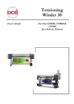
User’s Guide Unwinder/Winder 100 Applicable for: Blizzard 65/90 Spitfire 65/90 Extreme Rockhopper 3 Extreme ValueJet 1604 ValueJet 1604 W ValueJet 1614 Viper 65/90 Viper 65/90 Extreme Viper 100 ValueJet 1624 ValueJet 1638 ValueJet 1638 W ValueJet 1608 Hybrid Unwinder / Winder 100 – User’s Guide This page is intentionally left blank 2 AP-75101, Rev.4.1, 09.07.2012 Unwinder / Winder 100 – User’s Guide COPYRIGHT NOTICE COPYRIGHT © 2012 Mutoh Europe nv all rights reserved. This document may not be reproduced by any means, in whole or in part, without written permission of the copyright owner. This document is furnished for the installation and operation of Mutoh’s Unwinder / Winder 100 for Blizzard 65/90, Spitfire 65/90 Extreme, Rockhopper 3 Extreme, Viper 65/90, Viper 65/90 Extreme, Viper 100, ValueJet 1604, ValueJet 1604 W ValueJet 1608 Hybrid and ValueJet 1614. In consideration of the furnishing of the information contained in this document, the party to whom it is given, assumes its custody and control and agrees to the following: The information herein contained is given in confidence, and any part thereof shall not be copied or reproduced without written consent of Mutoh Europe nv. This document or the contents herein under no circumstances shall be used in the manufacture or reproduction of the article shown and the delivery of this document shall not constitute any right or license to do so. 09 July 2012 Published: Mutoh Europe nv, Archimedesstraat 13, B-8400 Oostende, BELGIUM 3 AP-75101, Rev.4.1, 09.07.2012 Unwinder / Winder 100 – User’s Guide This page is intentionally left blank 4 AP-75101, Rev.4.1, 09.07.2012 Unwinder / Winder 100 – User’s Guide TABLE OF CONTENTS 1 Safety Instructions.......................................................................................................... 7 1.1 Regulations ................................................................................................................ 7 1.2 Introduction ................................................................................................................ 8 1.3 Important safety instructions ...................................................................................... 8 1.4 Operation labels .........................................................................................................9 2 Product Overview ......................................................................................................... 11 2.1 Part names and functions ......................................................................................... 11 2.1.1 Operation Panel ................................................................................................. 12 2.2 Verifying the packaged items ................................................................................... 13 2.2.1 Blizzard, Rockhopper 3, Spitfire, Viper (Extreme) and Viper 100. ..................... 13 2.2.1.1 Packaging box............................................................................................. 13 2.2.1.2 Winder kit .................................................................................................... 14 2.2.2 ValueJet 16xx series.......................................................................................... 15 2.2.2.1 Packaging box............................................................................................. 15 2.2.2.2 Winder kit .................................................................................................... 16 3 Installing the unit .......................................................................................................... 17 3.1 General sequence .................................................................................................... 17 3.2 Install all parts .......................................................................................................... 18 3.2.1 Mounting the roll unit bars ................................................................................. 19 3.2.2 Mounting the brackets for the tensioning bars ................................................... 21 3.2.2.1 On a Blizzard, Spitfire, Rockhopper 3, Viper (Extreme) and Viper 100 ....... 21 3.2.2.2 On a ValueJet 16XX series printer .............................................................. 22 3.2.3 Installing the tensioning bars ............................................................................. 23 3.2.4 Mounting the PCB Box ...................................................................................... 25 3.2.5 Connecting the cables. ...................................................................................... 26 3.3 Calibrating the UW/W 100 ........................................................................................ 28 3.3.1 Calibrating the rear tensioning system............................................................... 28 3.3.1.1 Checking the calibration .............................................................................. 28 3.3.1.2 Adjusting the tensioning systems ................................................................ 32 3.3.2 Calibrating the front and rear roll unit bars. ........................................................ 34 3.3.2.1 Introduction ................................................................................................. 34 3.3.2.2 Checking the calibration of the roll units ...................................................... 34 3.3.2.3 Adjusting the roll units ................................................................................. 38 3.3.3 Adjusting the weight supports under the UW/W 100.......................................... 40 3.3.3.1 Location of the weight supports on a 65” printer ......................................... 40 3.3.3.2 Location of the weight supports on a 90” printer ......................................... 40 3.3.3.3 Adjusting the weight supports ..................................................................... 41 4 Operating the system ................................................................................................... 43 4.1 Switching the power ON / OFF ................................................................................. 43 4.2 Loading roll media .................................................................................................... 44 4.2.1 On a Blizzard and Viper Extreme ................................................................................... 44 4.2.2 On a Viper 100 ............................................................................................................... 48 4.2.3 On a Spitfire, Rockhopper or ValueJet........................................................................... 51 5 AP-75101, Rev.4.1, 09.07.2012 Unwinder / Winder 100 – User’s Guide This page is intentionally left blank 6 AP-75101, Rev.4.1, 09.07.2012 Unwinder / Winder 100 – User’s Guide Chapter 1 : Safety instructions 1 SAFETY INSTRUCTIONS 1.1 REGULATIONS The CE marking is a mandatory European marking for certain product groups to indicate conformity with the essential health and safety requirements set out in European Directives. By affixing the CE marking, the manufacturer, his authorized representative, or the person placing the product on the market or putting it into service ensures that the item meets all the essential requirements of all applicable EU directives and that the applicable conformity assessment procedures have been applied. This product is tested and approved by the Canadian Standards Association (CSA), this to provide increased assurance of quality and safety. The product is tested according to IEC60950. This standard tries to cover all safety aspects. • Mechanical, electrical • Choice of components • Choice of materials: flammability! • Connectors, cables … • Fire enclosure • … This means the product is safe for users, service personnel and production personnel. CSA International certification is not a legal commitment but it assures the quality and safety of the machine. WEEE regulations Your product is designed and manufactured with high quality materials and components, which can be recycled and reused. When this crossed-out wheeled bin symbol is attached to a product it means the product is covered by the European Directive 2002/96/EC Please inform yourself about the local separate collection system for electrical and electronic products. Please act according to your local rules and do not dispose of your old products with your normal household waste. The correct disposal of your old product will help prevent potential negative consequences for the environment and human health. FCC This equipment has been tested and found to comply with the limits for a Class A digital device, pursuant to Part 15 of the FCC Rules. These limits are designed to provide reasonable protection against harmful interference when the equipment is operated in a commercial environment. This equipment generates, uses, and can radiate radio frequency energy and, if not installed and used in accordance with the instruction manual, may cause harmful interference to radio communications. Operation of this equipment in a residential area is likely to cause harmful interference in which case the user will be required to correct the interference at his own expense. ICES This Class A digital apparatus complies with Canadian ICES-003. 7 AP-75101, Rev.4.1, 09.07.2012 Unwinder / Winder 100 – User’s Guide Chapter 1 : Safety instructions 1.2 INTRODUCTION Important BE SURE TO READ THE TERMS IN THE NEXT CHAPTER THOROUGHLY BEFORE INSTALLING AND OPERATING THE SYSTEM FOR YOUR OWN SAFETY. All safety related terms are bundled and categorized in three types. Safety terms Important Caution Notes Details Must be followed carefully to avoid death or serious bodily injury Must be followed to avoid bodily injury (moderate or light) or damage to your equipment Contains important information and useful tips on the operation of your printer 1.3 IMPORTANT SAFETY INSTRUCTIONS General safety instructions that must be observed to use the equipment safely are explained below. Do not stand on or place heavy objects on the unit. Doing so may result in the unit tipping or falling over and causing injury. Do not attempt to plug in electrical plugs with wet hands. Doing so may result in electrical shock. Do not use thinner, benzene, alcohol or other active agents. Doing so may result in damage or paint peeling from the casing. Be careful not to spill water inside the winder. Doing so may result in a short-circuit. Never open the covers fixed with screws. Doing so may result in electrical shock or a malfunctioning in the unit. When setting roll media, place it on top of a desk or other flat surface 8 AP-75101, Rev.4.1, 09.07.2012 Unwinder / Winder 100 – User’s Guide Chapter 1 : Safety instructions 1.4 OPERATION LABELS The operation labels mentioned below are attached to areas to which attention must be paid. • • • Notes Make sure that all labels are recognizable. If text or illustrations are invisible, clean the label. When cleaning labels, use a cloth with water or neutral detergent. Do not use a solvent or gasoline. If an operation label has been damaged, lost or cannot be recognized, replace the label. Foot switch label Roll unit handle label Front tensioning label Rear tensioning label PCB box label 9 AP-75101, Rev.4.1, 09.07.2012 Unwinder / Winder 100 – User’s Guide Chapter 1 : Safety instructions This page is intentionally left blank 10 AP-75101, Rev.4.1, 09.07.2012 Unwinder / Winder 100 – User’s Guide Chapter 2 : Product overview 2 PRODUCT OVERVIEW 2.1 PART NAMES AND FUNCTIONS 5 6 7 Blizzard And Viper 100 ONLY Blizzard And Viper 100 ONLY 8 9 4 N° 3 Name 2 1 Function Roll unit bar Supports the roll units. 2 Roll unit Supports the roll media. Adjust the tension between the print platform and the winding system. Tensioning bar + light tension weight Remove the weight mounted on the back to reduce the tension. (Only for Blizzard and Viper 100 ) Supports and winds up the roll media. It is possible to fix the media core with the tensioning screw (Only for Blizzard and Viper 100 ) Supports and unwinds the roll media. It is possible to fix the media core with the tensioning screw (Only for Blizzard and Viper 100 ) Adjust the tension between the print platform and the unwinding system. 3 FRONT 1 Motorized roll unit + tensioning screw 5 Motorized roll unit + tensioning screw 6 REAR 4 Tensioning bar + light tension weight 7 Roll unit bar Remove the weight mounted on the back to reduce the tension. (Only for Blizzard and Viper 100 ) Supports the roll units. 8 Roll unit Supports the roll media. 9 PCB Box Contains the boards to control the UW/W 100. 10 Operation panel To control the unwinder winder 100 manually or automatically 11 AP-75101, Rev.4.1, 09.07.2012 Unwinder / Winder 100 – User’s Guide Chapter 3: Installing the unit 2.1.1 Operation Panel N° A B / / Name 1 Print Side Selector 2 Unwinder 100 switch Manual 3 Unwinder 100 LED 4 5 6 Backwards button Forwards button Winder 100 switch Automatic Manual 7 Winder 100 LED 8 9 10 Backwards button Forwards button Power LED Automatic Function Part of the operation panel controlling the unwinder 100. Part of the operation panel controlling the winder 100. In case you loaded media with printed side on the outside select ‘OUT’, otherwise select ‘IN’. Toggle between Manual (“0”) and Automatic (“I”) mode. LED lights up when pushing one of the buttons Motor turns: LED flashes. Motor is off: LED is out. Motor accelerates: LED burns continuously. Outside printing Inside printing Roll-off unwinder Roll-up unwinder Roll-up unwinder Roll-off unwinder Toggle between Manual (“0”) and Automatic (“I”) mode. LED lights up when pushing one of the buttons Motor turns: LED flashes Motor is off: LED is out. Motor accelerates: LED burns continuously. Outside printing Inside printing Roll-off winder Roll-off winder Roll-up winder Roll-up winder Lightens up if the system is ON. 12 AP-75101, Rev.4.1, 09.07.2012 Unwinder / Winder 100 – User’s Guide Chapter 3: Installing the unit 2.2 VERIFYING THE PACKAGED ITEMS Inspect the unit for damage and check that all necessary parts are present. Notes • The parts which are not described are buffers to hold the parts in their position and to protect them. • If there is any part missing or broken, contact your local Mutoh dealer/distributor. 2.2.1 Blizzard, Rockhopper 3, Spitfire, Viper (Extreme) and Viper 100. 2.2.1.1 Packaging box N° 1 4 * Part Description Box 1: Bracket arms Quantity 1 2 Left bracket 1 3 Keyboard bracket 1 Box 2 : PCB box 1 * 1 5 Box 3 : Winder kit 6 Roll unit bar 2 7 Rear tensioning bar 1 8 Front tensioning bar 1 Please refer to the next page for the contents of this box 13 AP-75101, Rev.4.1, 09.07.2012 Unwinder / Winder 100 – User’s Guide Chapter 3: Installing the unit 2.2.1.2 Winder kit N° 1 Part Description PET adjusting strip Quantity 1 2 Hexagon key 2.5 mm 1 3 Hexagon key 3 mm 1 4 Hexagon key 4 mm 1 5 Hexagon key 5 mm 1 6 Hexagon key 6 mm 1 7 Philips screwdriver p2 1 8 Spacer 10 9 Foot switch 1 10 Motor twist cable 1 11 Adjustment plate 1 12 D-lock shafts 2 13 Keyboard cable 1 14 Screw set 1 15 Screw M4x10 4 16 Screw M3x5 4 17 Screw M5x8 2 18 Screw M6x16 16 19 Washer M5 20 Spring washer M6 16 21 Washer M6 16 22 Lock washer M6 4 1 14 AP-75101, Rev.4.1, 09.07.2012 Unwinder / Winder 100 – User’s Guide Chapter 3: Installing the unit 2.2.2 ValueJet 16xx series. 2.2.2.1 Packaging box N° 1 4 * Part Description Box 1: Bracket arms Quantity 1 2 Left bracket 1 3 Keyboard bracket 1 Box 2 : PCB box 1 * 1 5 Box 3 : Winder kit 6 Roll unit bar 2 7 Rear tensioning bar 1 8 Front tensioning bar 1 Please refer to the next page for the contents of this box 15 AP-75101, Rev.4.1, 09.07.2012 Unwinder / Winder 100 – User’s Guide Chapter 3: Installing the unit 2.2.2.2 Winder kit N° 1 Part Description PET adjusting strip 2 Hexagon key 2.5 mm 1 3 Hexagon key 3 mm 1 4 Hexagon key 4 mm 1 5 Hexagon key 5 mm 1 6 Hexagon key 6 mm 1 7 Philips screwdriver p2 1 8 Spacer 10 9 Foot switch 1 10 Motor twist cable 1 11 Adjustment plate 1 12 Lock shafts 2 13 Keyboard cable 1 14 Power cable (EU + UK) 2 15 Screw set 1 25 Quantity 1 16 Screw M4x10 4 17 Screw M3x5 4 18 Screw M5x8 2 19 Screw M6x16 8 20 Self locking screws M6x16 8 21 Synthetic Washer M5 4 22 Spring washer M6 8 23 Washer M6 8 24 Lock washer M6 1 User’s Guide 1 16 AP-75101, Rev.4.1, 09.07.2012 Unwinder / Winder 100 – User’s Guide Chapter 3: Installing the unit 3 INSTALLING THE UNIT 3.1 GENERAL SEQUENCE UNPACK ALL ITEMS ▼ MOUNT THE ROLL UNIT BARS ▼ MOUNT THE BRACKETS FOR THE TENSIONING BARS ▼ INSTALL THE PCB BOX ▼ INSTALL THE TENSIONING BARS ▼ CALIBRATE THE UNWINDER / WINDER 100 ▼ ADJUST THE WEIGHT SUPPORTS UNDER THE ROLL UNIT BARS 17 AP-75101, Rev.4.1, 09.07.2012 Unwinder / Winder 100 – User’s Guide Chapter 3: Installing the unit 3.2 INSTALL ALL PARTS • Important installation information There are 2 types of stands in circulation for the 64” units Type 1 Type 2 Colour: Dark grey Wider foot (W x L: 235 x 680 mm) • Colour: light grey Narrow foot (W x L: 150 x 810 mm) In case an Unwinder winder 100 needs to be mounted on the 2nd type, install the mounting kit (KY-14605). Please refer to the instruction sheet bundled in the box. In case an Unwinder winder 100 needs to be mounted on the first type, please continue in this document. 18 AP-75101, Rev.4.1, 09.07.2012 Unwinder / Winder 100 – User’s Guide Chapter 3: Installing the unit 3.2.1 Mounting the roll unit bars Parts and Tools needed N° Description 1 2 3 4 5 Roll unit bar Hexagon bolt M6x16 Plain washer M6 Tooth lock washer M6 Hexagon wrench 5 mm Quantity needed RH3 – SPFR ValueJet 2 2 8 8 8 8 8 8 1 1 Procedure Step 1 : Position the roll unit bars (1) on the printer stand as shown on the image below. 19 AP-75101, Rev.4.1, 09.07.2012 Unwinder / Winder 100 – User’s Guide Step 2 : Chapter 3: Installing the unit Mount the left side of the bars with the mounting supports to the printer’s stand as indicated on the image below. N° 1 2 3 Step 3 : Description Plain washer M6 Tooth lock washer M6 Hexagon bolt M6x12 Check the gap (s) between the adjustable mounting support (1) on the right hand side and the printer stand and perform the correct action. This has to be done for both roll unit bars. See below. N° 1 2 3 IF … Description Adjustable mounting support Left mounting support Gap between support and printer foot THEN … • s = 1 or s > 1 mm • • s < 1mm • loosen the 4 screws holding the support on the roll unit bar, (do not unscrew completely) slide the support against the right side of the printer’s stand, Mount the support to the printer’s stand and fix the 4 screws holding the support on the roll unit bar. Fix the support to the printer’s stand without adjusting. 20 AP-75101, Rev.4.1, 09.07.2012 Unwinder / Winder 100 – User’s Guide Chapter 3: Installing the unit 3.2.2 Mounting the brackets for the tensioning bars 3.2.2.1 On a Blizzard, Spitfire, Rockhopper 3, Viper (Extreme) and Viper 100 Parts and Tools needed N° 1 2 3 4 5 6 7 Description Right bracket Left bracket Hexagon bolt M6x16 Plain washer M6 Spring washer M6 Tooth lock washer M6 Hexagon wrench 5 mm Quantity 1 1 8 8 8 1 1 Instructions Step 1 : Mount the left and right bracket to the bottom of the X-rail. Note that the positioning of the left and right bracket is different depending on the size of the machine. N° 1 2 3 4 5 Step 2 : Description Left bracket arm Unused holes Left leg of the printer stand Right leg of the printer stand Right bracket arm Fix the screws of the right bracket. Do NOT fix the screws of the left (adjustable) bracket yet. N° 1 2 3 Description Hexagon bolt M6x16 Spring washer M6 Plain washer M6 21 AP-75101, Rev.4.1, 09.07.2012 Unwinder / Winder 100 – User’s Guide Chapter 3: Installing the unit 3.2.2.2 On a ValueJet 16XX series printer Parts and Tools needed N° 1 2 3 4 5 Description Right bracket Left bracket Self locking bolt M6x16 Tooth lock washer M6 Hexagon wrench 5 mm Quantity 1 1 8 1 1 Instructions • Notes Before installing the winding system on a ValueJet, we recommend loosening the screws fixing the printer from its stand and push it to the rear and tighten the bolts again. This to be sure that the machine is well positioned. Step 1 : Screw the self-locking bolts (M6x 16) half way in. Step 2 : Hook the left and right bracket over the four screws and pull. Step 3 : Tighten the bolts of the right bracket. 22 AP-75101, Rev.4.1, 09.07.2012 Unwinder / Winder 100 – User’s Guide Chapter 3: Installing the unit 3.2.3 Installing the tensioning bars Parts and Tools needed N° Description 1 2 5 6 7 Front tensioning bar Rear tensioning bar Pan head screw flat M4x10 Philips screwdriver Hexagon wrench 5 mm Quantity RH3, SPFR & Viper VJ-16XX series 1 1 1 1 4 4 1 1 1 1 Procedure Step 1 : Remove the cover of the right bracket. Step 2 : Position the front tensioning bar (1) between the D-lock shafts of the left and right bracket in such a way that it fits the corresponding D hole in the plates (2) of the tensioning bars. • Notes Be sure to position the D-lock shaft as shown on picture 1. If the D-lock shaft is turned an extra 360° or more, the grounding cable will be turned around the shaft as shown on picture 2 which will damage the electronics. Picture 1 Picture 2 23 AP-75101, Rev.4.1, 09.07.2012 Unwinder / Winder 100 – User’s Guide Chapter 3: Installing the unit Step 3 : Fix the front tensioning bar with 2 times an M4x10 screw. Step 4 : Do the same for the rear tensioning bar. Only remove the cover of the left bracket instead of right. Also be sure that the D-shaft is positioned as shown on the picture below, to avoid the grounding cable to get turned around the shaft. Step 5 : Tighten the bolts of the left bracket. • Caution Be sure to calibrate the complete system before using it. Please refer to the next chapter for this issue. 24 AP-75101, Rev.4.1, 09.07.2012 Unwinder / Winder 100 – User’s Guide Chapter 3: Installing the unit 3.2.4 Mounting the PCB Box Parts and Tools needed N° 1 2 3 4 Description PCB Box Screw M5x8 Washer M5 Hexagon wrench 3 mm Quantity 1 2 4 1 Procedure Step 1 : Mount the two screws with each two spacers to the stand. Step 2 : Place the PCB Box (2) against the stand and slide it with the holes over the screws (1) and push it downwards to fix it. 25 AP-75101, Rev.4.1, 09.07.2012 Unwinder / Winder 100 – User’s Guide Chapter 3: Installing the unit 3.2.5 Connecting the cables. • • • • Caution Use a power cable that is suitable to the local power specifications when connecting the UW/W 100 to the power grid. If ordering the kit as an optional item, a power cable is included in the UW/W 100 kit If the UW/W 100 kit has been delivered with a new printer as a standard in the box item, then the power cable is located in the printer’s packaging box, not in UW/W 100 packaging box. If the power cable is damaged, contact : o The shop where you bought the product o Your MUTOH local dealer Step 1 : Connect the power cable to the power supply connector. Step 2 : Insert the flat cable that connects the pcb board with the keyboard. Flat cable connected to the PCB board • Flat cable connected to the keyboard Notes Fasten the flat cable to the connector with 2 screws. 26 AP-75101, Rev.4.1, 09.07.2012 Unwinder / Winder 100 – User’s Guide Step 3 : Chapter 3: Installing the unit Check if the all cables of the UW/W are connected to the correct connector (1 to 6). See image below for the location of the connectors. N° 1 2 3 4 5 6 • • Description Power supply connector Front motorized unit connector Rear motorized unit connector Foot switch connector Not used Operation panel connector Notes With a small intervention it is possible to reverse your winding direction. Mount the Motor twist cable between the control box and the front motorized unit cable. 27 AP-75101, Rev.4.1, 09.07.2012 Unwinder / Winder 100 – User’s Guide Chapter 3: Installing the unit 3.3 CALIBRATING THE UW/W 100 3.3.1 Calibrating the rear tensioning system Parts and Tools needed Included in kit N° 1 2 3 4 Description Synthetic paper strip Hexagon wrench 2,5 mm Hexagon wrench 3 mm Hexagon wrench 4 mm N° 1 2 Description Tape Pencil Quantity 1 1 1 1 NOT included in kit Quantity 1 1 3.3.1.1 Checking the calibration The procedure below describes the calibration check of the rear tensioning system. The procedure to check the front tensioning system is the same. Procedure: PART 1: PREPARING THE SYNTHETIC PAPER STRIP Step 1 : Put the pressure rollers in the up position. Step 2 : Go to the back of the machine. Step 3 : Create a loop with the synthetic paper strip around the upper bar of the rear tension system at the left side when standing at the back of the printer. 28 AP-75101, Rev.4.1, 09.07.2012 Unwinder / Winder 100 – User’s Guide Chapter 3: Installing the unit Step 3 : Check if the edges of the loop are aligned on each other. Step 4 : Slide the end of the strip (1) under the pressure rollers (4) and move it to position 1 as shown on the picture below. N° 1 2 3 4 Description Synthetic paper strip Paper loop Tensioning bars Pressure rollers Step 5 : Go to the FRONT SIDE of the printer. Step 6 : Carefully pull the strip to create some tension. • • Caution Don’t pull too hard on the strip. This will loosen the tape, resulting in the fact that the loop becomes longer, leading to a bad calibration check. Make sure that you have an equal tension on the left and right of the strip. 29 AP-75101, Rev.4.1, 09.07.2012 Unwinder / Winder 100 – User’s Guide Chapter 3: Installing the unit PART 2: DRAWING THE CONTROL LINES Step 1 : Place the adjustment plate onto the strip and slide it against the pressure rollers. Step 2 : Draw a line on the strip. Step 3 : Slide the strip (1) to position 2 as indicated on the image below. N° 1 2 3 4 Description Synthetic paper strip Paper loop Tensioning bars Pressure rollers 30 AP-75101, Rev.4.1, 09.07.2012 Unwinder / Winder 100 – User’s Guide Step 4 : • • Chapter 3: Installing the unit Carefully pull the strip to create some tension. Caution Don’t pull too hard on the strip. This will loosen the tape, resulting in the fact that the loop becomes longer, leading to a bad calibration check. Make sure that you have an equal tension on the left and right of the strip. Step 5 : Place the adjustment plate onto the strip and slide it against the pressure rollers. Step 6 : Draw a line for the second time. The following situations are possible. Line overlap each other Line does NOT overlap each other ► well adjusted ► perform the adjustment procedure as described in the next chapter 31 AP-75101, Rev.4.1, 09.07.2012 Unwinder / Winder 100 – User’s Guide Chapter 3: Installing the unit 3.3.1.2 Adjusting the tensioning systems Introduction The present topic describes the adjustment of the REAR tensioning system. The procedure to adjust the front tensioning system is the same. Procedure Step 1 : Standing at the REAR SIDE of the unit, remove the cover (1) of the adjustable bracket (3). Tool : Hexagon wrench 2,5 mm N° 1 2 3 Step 2 : Description Cover Screws Adjustable bracket Loosen (don’t remove) the 4 screws on the side of the adjustable bracket. Tool: Hexagon wrench 4 mm N° 1 2 Description Screws Adjustable bracket 32 AP-75101, Rev.4.1, 09.07.2012 Unwinder / Winder 100 – User’s Guide Step 3 : Chapter 3: Installing the unit Use the 2 screws (1) in the tension bar bracket to adjust the tension system. Tool: Hexagon wrench 3 mm 1 = Adjustment screws IF Line 2 lays… THEN turn the adjustment screws as follows : BEFORE line 1 (Case A on image above) BEHIND line 1 (Case B on image above) • Caution Make sure to turn both adjustment screws an equal amount of turns. Step 4 : Check the calibration again and repeat the adjustment until the lines overlap each other. 33 AP-75101, Rev.4.1, 09.07.2012 Unwinder / Winder 100 – User’s Guide Chapter 3: Installing the unit 3.3.2 Calibrating the front and rear roll unit bars. 3.3.2.1 Introduction The heights (hL and hR) on both sides of the roll unit bar (2) in relation to the printer stand (1) have to be adjusted with spacers (3) to calibrate a roll unit bar (2). FRONT VIEW N° 1 2 3 Description Printer stand Roll unit bar Spacer 3.3.2.2 Checking the calibration of the roll units The procedure below describes the calibration check of the FRONT roll unit. The procedure to check the rear roll unit is the same. In the procedure, line 1 is drawn at the RIGHT side of the printer, line 2 at its LEFT side. Procedure PART 1: PREPARING THE SYNTHETIC PAPER STRIP Step 1 : Put the pressure rollers in the ‘up’ position. Step 2 : Install an empty core between the roll unit and the motorized roll unit at the front side of the printer. Step 3 : Standing in front of the printer, use some tape to create a loop around the core with the synthetic paper strip. N° 1 Description Core 34 AP-75101, Rev.4.1, 09.07.2012 Unwinder / Winder 100 – User’s Guide Chapter 3: Installing the unit Step 4 : Check if the edges of the loop (indicated on the images below) are aligned on each other. Step 5 : Slide the end of the synthetic paper strip (1) under the pressure rollers (4) in position 1 of the printer until the synthetic paper strip (1) is a little tensioned. N° 1 2 3 4 • • Description Synthetic paper strip Loop Core Pressure rollers Caution Don’t pull too hard on the strip. This will loosen the tape, resulting in the fact that the loop becomes longer, leading to a bad calibration check. Make sure that you have an equal tension on the left and right of the strip. 35 AP-75101, Rev.4.1, 09.07.2012 Unwinder / Winder 100 – User’s Guide Chapter 3: Installing the unit PART 2: DRAWING THE CONTROL LINES Step 1 : Standing at the front side of the unit, place the adjustment plate onto the strip and position it against the pressure rollers as indicated on the image below. Step 2 : Draw a line. See image below. Step 3 : Slide the strip (1) to position 2 as indicated on the image below. N° 1 2 3 4 Description Synthetic paper strip Loop Core Pressure rollers 36 AP-75101, Rev.4.1, 09.07.2012 Unwinder / Winder 100 – User’s Guide Chapter 3: Installing the unit Step 4 : Place the adjustment plate onto the strip and slide it against the pressure rollers. Step 5 : Pull the strip so there is an equal tension. • • Caution Don’t pull too hard on the strip. This will loosen the tape, resulting in the fact that the loop becomes longer, leading to a bad calibration check. Make sure that you have an equal tension on the left and right of the strip. Step 6 : Draw a line for the second time. The following situations are possible. Line overlap each other Line does NOT overlap each other ► well adjusted ► perform the adjustment procedure as described in the next chapter 37 AP-75101, Rev.4.1, 09.07.2012 Unwinder / Winder 100 – User’s Guide Chapter 3: Installing the unit 3.3.2.3 Adjusting the roll units Procedure Step 1 : Use the correct amount of spacers (2) to cover the space between the drawn lines (1). N° 1 2 Step 2 : Description Drawn lines Spacer Determine the deviation of the roll unit using the image and table below. IF line 2 lays… BEFORE line 1 BEHIND line 1 Adjusting the FRONT Units THEN… Remove spacers on the left front unit or add spacers on the right front unit. Add spacers on the left front unit or remove spacers on the right front unit. IF line 2 lays… BEFORE line 1 BEHIND line 1 Adjusting the REAR Units THEN… Add spacers on the left rear unit or remove spacers on the right rear unit. Remove spacers on the left rear unit or add spacers on the right rear unit. 38 AP-75101, Rev.4.1, 09.07.2012 Unwinder / Winder 100 – User’s Guide Step 3 : Chapter 3: Installing the unit Insert these spacers (1) at the left or right side (depending on the deviation determined in the previous step) BETWEEN the roll unit bar (3) and the printer’s stand (2). (See images below) N° 1 2 3 Description Spacer Printer’s stand Roll unit bar Step 4 : Check the calibration of the roll system again and do an adjustment again if necessary. Step 5 : Now fix the screws of the roll unit bar so the bar doesn’t move anymore. 39 AP-75101, Rev.4.1, 09.07.2012 Unwinder / Winder 100 – User’s Guide Chapter 3: Installing the unit 3.3.3 Adjusting the weight supports under the UW/W 100 Parts and Tools needed N° 1 Description Hexagon wrench 3 mm Quantity 1 3.3.3.1 Location of the weight supports on a 65” printer There are 2 weight supports on the UW/W 100 system for a 65” machine, see the images below for their positions. FRONT VIEW N° 1 Description Weight support 3.3.3.2 Location of the weight supports on a 90” printer There are 4 weight supports on the UW/W 100 system for a 90” machine, see the images below for their positions. FRONT VIEW N° 1 Description Weight support 40 AP-75101, Rev.4.1, 09.07.2012 Unwinder / Winder 100 – User’s Guide Chapter 3: Installing the unit 3.3.3.3 Adjusting the weight supports • Caution Don’t turn the weight supports with force when they reach the floor! Instructions Lower the weight supports of the UW/W 100 till they reach the floor. A hexagon wrench 6 mm must be used. N° 1 2 Description Hexagon wrench 6 mm Turning direction to lower the support 41 AP-75101, Rev.4.1, 09.07.2012 Unwinder / Winder 100 – User’s Guide Chapter 4 : Operating the system 42 AP-75101, Rev.4.1, 09.07.2012 Unwinder / Winder 100 – User’s Guide Chapter 4 : Operating the system 4 OPERATING THE SYSTEM 4.1 SWITCHING THE POWER ON / OFF The switch is located on the power supply box. Its status is marked with “O” and “I”. “I” Switched ON Power LED on control panel of winding system will light up “O” Switched OFF Power LED on control panel of winding system will not be lid. The PCB box will start the initialization. Via the LED flashing combination on the Control Panel of the Winder, it is possible to know which firmware version has been installed. The firmware version exists out of three digits, for example 2.0.3. The flashing sequence will be: Flashing 2 seconds long Flashing 2 time short 2 Flashing 2 seconds long Flashing 0 time short 0 Flashing 2 seconds long Flashing 3 time short 3 long 1 short 1 2 long short long 1 0 1 1 short 2 3 long 1 LED ON 43 AP-75101, Rev.4.1, 09.07.2012 Unwinder / Winder 100 – User’s Guide Chapter 4 : Operating the system 4.2 LOADING ROLL MEDIA 4.2.1 On a Blizzard and Viper Extreme Please follow the procedure below to install and load roll media. Step 1 : Make sure the printer and Unwinder/Winder 100 are switched ON. Step 2 : Raise the pressure rollers of the printer. Step 3 : Open the front cover Step 4 : Make sure both unwinder (REAR) and winder (FRONT) unit are set to MANUAL mode (=0). Step 5 : Consider the specifications of the printer before loading media: Maximum loading capacity Maximum media width For a 65” printer For a 90” printer Minimum media width Inner core diameter Metrical 100 kg Imperial 220 lb 1651 mm 2240 mm 210 mm 50.8 mm or 76.2 mm 65” 88.18” 8,27” 2” or 3” Step 6 : Remove the packaging of the media roll. Step 7 : Check whether the media is inside or outside printable. This affects the installation method on the unwinder at the rear of the machine. Rear Front OUTSIDE PRINTABLE MEDIA Rear Front INSIDE PRINTABLE MEDIA Step 8 : Loosen the handles to move the roll units left and right until the media core fits in between. Step 9 : Install the media between the two roll units at the back of the machine. 44 AP-75101, Rev.4.1, 09.07.2012 Unwinder / Winder 100 – User’s Guide Chapter 4 : Operating the system Move the media roll and roll units to the desired position and tighten them with the handles. Step 10 : With the Blizzard, it is highly recommend loading media at the most right side of the printer (next to media holes on the media guide): + + + Speed gain. Working within the specifications set by Mutoh. Profiles are optimized to print on right loaded media. When printing on media smaller than 50” though, we recommend centre loading the media. Verification is easy via the yellow labels on the winding rails. Just mount the left and right roll unit on the same distance from the 0I0 label. Please note however, that most profiles are generated on wider media and that they may not optimally perform. In this case, dedicated profiles may be required. With the Viper Extreme, we recommend loading media in the middle of the printer. X Y Step 11 : Tighten the wheel at the side to fix the media core between the two roll units. Step 12 : Install an empty core between the front roll units in the same way as described above. a. Make sure the core is longer than the media width. b. Load it central or at the right side as described in previous step Step 13 : Use the foot-switch to release some media at the rear. 45 AP-75101, Rev.4.1, 09.07.2012 Unwinder / Winder 100 – User’s Guide Step 14 : Chapter 4 : Operating the system Load media through the rear tensioning bar, over the print platform, under the pressure rollers as pictured below. Outside printable media 1 2 3 4 Inside printable media Roll unit Media roll Rear tensioning bar Print platform and pressure rollers Step 15 : Take the media on the front of the printer and pull until the rear tensioning system gently hits the back of the machine to become an equal tension. Step 16 : Lower the pressure rollers. Step 17 : Go to the front of the machine, lever up. Step 18 : For the viper Extreme, position the ETT correctly according to the media. Step 19 : Set the winder to OFF. Step 20 : Take the front of the media and pull down. Make sure the tension left and right are equal. Step 21 : Tape the middle of the media to the empty core. 1 2 3 46 Roll unit Empty core Front tensioning bar AP-75101, Rev.4.1, 09.07.2012 Unwinder / Winder 100 – User’s Guide Chapter 4 : Operating the system Step 22 : Fix the sides of the media to the empty core without pulling. Step 23 : Lower the pressure rollers. Step 24 : Release the front swingbar. Step 25 : Set the unwinder (REAR) unit to AUTOMATIC. The rear tensioning system will go to its initial position. Notes Be sure to make the correct settings on the control panel of the winding system. OUTSIDE or INSIDE HINTS Hint 1 : To ease the winding up of the media on the front core, cut the media in a V-shape. Hint 2 : (Blizzard only) When printing at high speeds (> 20 m²/h), it might be possible that the printed media sticks to back of the already wound up media. To avoid this phenomenon, remove the installed weights to reduce the tension on the front swingbar. Step 26 : Place the media retainers correctly onto the media. Step 27 : Place on the right and the left side 3 pressure roller disablers. The Roll to Roll profile is the recommended setting when working with roll media. Step 28 : After closing the front cover, press the F4 key. The media initialize will start. Step 29 : Pull out the ETT when starting printing. Step 30 : Installation of the media is completed. Make sure that both the Unwinder (rear) and the Winder are set to Automatic. • Notes With a small intervention it is possible to reverse your winding direction. Mount the twist cable between the control box and the front motorized unit cable. 1 2 Normal winding direction Twisted motor cable attached 47 AP-75101, Rev.4.1, 09.07.2012 Unwinder / Winder 100 – User’s Guide Chapter 4 : Operating the system 4.2.2 On a Viper 100 Please follow the procedure below to install and load roll media. Make sure to have some strong tape available. Step 1 : Make sure the printer and Unwinder/Winder 100 are switched ON. Step 2 : Attach to both sides of the front swingbar the 150 g and to both sides of the rear swingbar 700 g if you want the media to be wound tighter, hang 700 g weights to both sides of the front swingbar. Step 3 : Set the front swing bar in the up position and fix the position with the 2 locking pens left and right. Step 4 : Put the rear winder button on auto (1) and the front winder to manual (0). Step 5 : Make sure the ETT is not pulled out. Step 6 : Place the media retainers in the foreseen grooves. The media retainer for the right side has an R on it. This one must be placed first and moved to the most right side. 48 AP-75101, Rev.4.1, 09.07.2012 Unwinder / Winder 100 – User’s Guide Step 7 : Chapter 4 : Operating the system Consider the specifications of the printer before loading media: Metrical 100 kg 2604 mm 50.8 mm or 76.2 mm Maximum loading capacity Maximum width Inner core diameter Imperial 220 lb 102.5 in 2 in or 3 in Step 8 : Install a media core brace in case the media is wider than 2050 mm. This to prevent the media to bend. Step 9 : Check if the extra tensioning wheel at the rear roll unit is at his minimum distance. Install the media between the two roll units at the back of the machine. Loosen the handles, and move the roll unit. At the back of the roll unit there is an extra tensioning wheel to fix the media roll tightly. When you have installed your media, move the extra tensioning wheel of the roll unit 2 times 360° so the core is well fixed. Extra tensioning wheel. Step 10 : Be sure to load the media is central. This to ensure the media is wound up straight. Verification is easy via the yellow labels on the winding rails. Be sure to mount the left and right roll unit on the same distance from the 0I0 label. Step 11 : Check if the extra tensioning wheel at the front roll unit is at the minimum distance. Install an empty core between the front roll units. Loosen the handles, and move the roll unit. At the back of the roll unit there is an extra tensioning wheel to fix the empty core tightly. When you have installed your empty core, move the extra tensioning wheel of the roll unit 2 times 360° so the core is well fixed. Step 12 : Press the [F4] key in the main menu to raise the pressure rollers or use the foot pedal of the printer. Step 13 : Open the front cover carefully using both handles. 49 AP-75101, Rev.4.1, 09.07.2012 Unwinder / Winder 100 – User’s Guide Step 14 : Chapter 4 : Operating the system Load media through the rear swingbar, over the print platform, under the pressure rollers as pictured below. 1 2 3 4 Roll unit Media roll Rear swingbar Print platform and pressure rollers Step 15 : Lever down. Step 16 : Go to the front of the machine, lever up. Step 17 : Position the ETT correctly according to the media. Step 18 : Set the winder to OFF. Step 19 : Take the front of the media and pull down. Make sure the tension left and right are equal. Step 20 : Tape the middle of the media to the empty core. • Notes It is best not to cut the front of the media in a V-shape. This to obtain a good tension to the left and right side of the paper. Step 21 : Fix the sides of the media to the empty core without pulling. Step 22 : Lower the pressure rollers. Step 23 : Release the front swingbar. Step 24 : Put the front winder and rear winder button on 1. 50 AP-75101, Rev.4.1, 09.07.2012 Unwinder / Winder 100 – User’s Guide Chapter 4 : Operating the system Step 25 : Place the media retainers correctly onto the media. Step 26 : Place on the right and the left side 3 pressure roller disablers. • We recommend the Roll to Roll profile when working with roll media. Step 27 : After closing the front cover, press the F4 key. The media initialize will start. Step 28 : Pull out the ETT when starting printing. Step 29 : Media installation is complete. • • Make sure that both the Unwinder (rear) and the Winder are set to Automatic. Notes With a small intervention it is possible to reverse your winding direction. Mount the twist cable between the control box and the front motorized unit cable. 1 2 Normal winding direction Twisted motor cable attached 4.2.3 On a Spitfire, Rockhopper or ValueJet Please follow the procedure below to install and load roll media. Step 1 : Make sure the printer and Unwinder/Winder 100 are switched ON. Step 2 : Raise the pressure rollers of the printer. Step 3 : Open the front cover Step 4 : Make sure both unwinder (REAR) and winder (FRONT) unit are set to MANUAL mode. Step 5 : Consider the specifications of the printer before loading media: Maximum loading capacity Maximum media width For ValueJet 16XX series For Spitfire 65”, Rockhopper 3 65” and Viper 65” For Spitfire 90”, Rockhopper 3 90” and Viper 90” Minimum media width For ValueJet 16XX series For Spitfire 65”, Rockhopper 3 65” and Viper 65” For Spitfire 90”, Rockhopper 3 90” and Viper 90” Inner core diameter 51 Metrical 100 kg Imperial 220 lb 1625 mm 1653 mm 2280 mm 63.98 in 65.07 in 89.76 in 1000 mm 210 mm 210 mm 50.8 mm or 76.2 mm 39.37 in 8.27 in 8.27 in 2 in or 3 inch AP-75101, Rev.4.1, 09.07.2012 Unwinder / Winder 100 – User’s Guide Chapter 4 : Operating the system Step 6 : Remove the packaging of the media roll. Step 7 : Check if the media is inside or outside printable. This affects the installation method on the unwinder at the rear of the machine. Step 8 : Install the media and core between the two roll units at the back of the machine. Loosen the handles to move the roll units left and right. Step 9 : Move the media roll and roll units to the desired position. We recommend loading media at the most right side of the printer (next to media holes on the media guide): + + + Speed gain. Working within the specifications set by Mutoh. Profiles are optimized to print on right loaded media. When printing on media smaller than 50” though, we recommend centre loading the media. Verification is easy via the yellow labels on the winding rails. Just mount the left and right roll unit on the same distance from the 0I0 label. Please note however, that most profiles are generated on wider media and that they may not optimally perform. In this case, dedicated profiles may be required. X Y Step 10 : Install an empty core between the front roll units. a. Make sure the core is longer than the media width. b. Load it central or at the right side as described in previous step 52 AP-75101, Rev.4.1, 09.07.2012 Unwinder / Winder 100 – User’s Guide Chapter 4 : Operating the system Step 11 : Use the foot-switch to release some media at the rear. Step 12 : Load media through the rear tensioning bar, over the print platform, under the pressure rollers as pictured below. 1 2 3 4 Outside printable Roll unit Media roll Rear tensioning bar Print platform and pressure rollers Inside Printable Step 13 : Take the media on the front of the printer and pull until the rear tensioning system gently hits the back of the machine. This to become an equal tension. Step 14 : Lower the pressure rollers Step 15 : Set the unwinder (REAR) unit to AUTOMATIC. The rear tensioning system will go to its initial position. • Notes Be sure to make the correct settings on the control panel of the winding system. OUTSIDE or INSIDE 53 AP-75101, Rev.4.1, 09.07.2012 Unwinder / Winder 100 – User’s Guide Chapter 4 : Operating the system Step 16 : Forward the media until you can stick it to the core installed between the front roll units. Make sure to have an equal tension on both sides of the media. 1 2 3 • Roll unit Empty core Front tensioning bar HINT To ease the winding up of the media on the front core, cut the media in a V-shape. Step 17 : Tighten the media straight to the core with tape. Step 18 : After closing the front cover, the media initialize will start. Step 19 : Set the winder (FRONT) unit to ACTIVE. The front tensioning system will be activated. Step 20 : Media installation is complete. • Notes With a small intervention it is possible to reverse your winding direction. Mount the twist cable between the control box and the front motorized unit cable. 54 AP-75101, Rev.4.1, 09.07.2012 Unwinder / Winder 100 – User’s Guide Chapter 4 : Operating the system This page is intentionally left blank 55 AP-75101, Rev.4.1, 09.07.2012