1
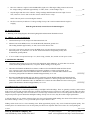
Remove the filter housing and coat all o-rings, gaskets and sealing surfaces with a medium to heavy grease, (Not oil) and reassemble.
Grease all valve stem packings and gently tighten gland nuts. Do not over tighten, valve handles should be able to turn freely. Tighten
all hose clamps and compression fittings (Do not over tighten). Run the engine for 5 to 10 minutes and observe GPH readings. If
you’ve found the problem, fluctuations should be reduced to less than ½ GPH.
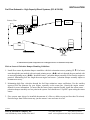
If this does not cure the problem, temporarily insert a clear piece of fuel resistant tubing in the fuel line. On diesel engines, install it
downstream of the forward flow sensor. Run the engine and watch for a constant stream of small bubbles in the clear tube, or an
occasional larger bubble. Sometimes shining a light through the tube makes bubbles easier to see.
Have someone observe the clear tube while you shake any flexible fuel hose(s). If the bubble stream continually increases or decreases
as you do this, you’ve found the leak area. Repair or replace as needed. If it is a one-time occurrence, you probably dislodged air
trapped in the fuel line.
If you haven’t found it yet, the last step is to inspect each pipe joint in the system. You should be able to see joint compound all
around the joint. If you do not, that joint is suspect and needs to be resealed. After re-sealing you may need to run the engine for a few
minutes to purge any remaining air. You should now see bubble free solid fuel running through the clear tube. If you still see bubbles
you missed a leak somewhere, recheck your work. Remove the tube and restore the fuel system to its normal condition.
Fuel Filters:
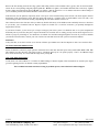
A dirty fuel filter, or one that is too fine (1-25 micron) will draw vapor bubbles out of the fuel. Replace it with a new 30-micron filter.
VII. FLOW SENSOR ORIENTATION
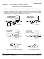
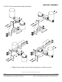
Sensor orientation is critical for proper operation. All Sensors have their inlet and outlet ports clearly marked (IN / OUT or Î Î).
This identifies fuel flow direction. The Sensor must be, “Plumbed” correctly for it to operate properly. There is an additional single
arrow on the Sensor body. It is crucial that this single arrow point up Ï.
VIII. LOW RPM OPERATION
At idle, under a no load condition, it is common for GPH readings to fluctuate slightly. These fluctuations are caused by the engine
governor regulating fuel flow to maintain a steady engine RPM.
This concludes Instrument and Sensor testing. If problems persist, contact FloScan Technical Support
4/17/2003
FloScan Instrument Company, Inc.
3016 NE Blakeley Street, Seattle, WA 98105
4001-103-00F
Tel: (206) 524-6625
Fax: (206) 523-4961
email: [email protected] http://www.floscan.com