1
USB/ Dual SD Player + Digital Mixer
OPERATING INSTRUCTIONS
IMPORTANT SAFETY INSTRUCTIONS
1. Read these instructions.
2. Keep these instructions.
3. Heed all warnings.
4. Follow all instructions.
5. Do not use the apparatus near water.
6. Clean only with dry cloth.
7. Do not block any ventilation openings. Install in accordance with the manufacturer’s instructions.
8. Do not install near any heat sources such as radiators, heat registers, stoves, or other apparatus (including
amplifiers) that produce heat.
9. Protect the power cord from being walked on or pinched particularly at plugs, convenience receptacles, and the
point where they exit from the apparatus.
10. Only use attachments/ accessories specified by the manufacturer.
11. Unplug this apparatus during lighting storms or when unused for long periods of time.
12. Refer all servicing to qualified service personnel. Servicing is required when the apparatus has been
damaged in any way, such as power-supply cord or plug is damaged, liquid has been spilled or objects
have fallen into the apparatus, the apparatus has been exposed to rain or moisture, does not operate
normally, or has been dropped.
WARNING
To reduce the risk of fire or electric shock, do not expose this apparatus to rain or moisture. The apparatus
shall not be exposed to dripping or splashing and that no objects filled with liquids, such as vases, shall be
placed on the apparatus.
DO NOT OPEN
RISK OF ELECTRIC SHOCK
CAUTION: To reduce the risk of electric shock, do not remove
any cover. No user-serviceable parts inside. Refer servicing to
qualified service personnel only.
The lightning flash with arrowhead symbol within the equilateral triangle is intended to alert the use
to the presence of un-insulated “dangerous voltage” within the product’s enclosure that may be of
sufficient magnitude to constitute a risk of electric shock.
The exclamation point within the equilateral triangle is intended to alert the user to the presence of
important operation and maintenance (servicing) instructions in the literature accompanying this
appliance.
CAUTION
To prevent electric shock, do not use this polarized plug with an extension cord, receptacle or other outlet
unless the blades can be fully inserted to prevent blade exposure.
1
MAIN FEATURES
y
Auto cue
y
Auto BPM
y
Pitch display
y
100% Anti-shock
y
Real time cue
y
Built-in audio mixer
y
Fast Track Search
y
Music Master tempo
y
SD & SDHC cards available
y
Mp3 Track Listings, ID3 Tags
y
1/75th second frame search
y
Jog Wheel Pitch Bend +/-100%
y
Big LCD Display with Backlight
y
Digital EQ, Mixing and Level Control
y
Folder Search, Multi-Cue Function
y
Cross fader start control for CD player
y
Headphone output with volume control
y
Selectable Single or Continuous Play
y
Supports memory device hot plug-and-play
y
MICROPHONE VOLUME CONTROL
y
Seamless Loop (uninterrupted loop playback)
y
MICROPHONE INPUT; BALANCED OUTPUT
y
Adjustable Pitch Percentages: +/-4%, +/-8%, or +/-16%
y
Compatible with USB 2.0/1.1/1.0 mass storage devices
y
Up to 4 seamless loops for every folder with reloop/stutter
y
4 CUE BANK BUTTONS can hold cue points or seamless loops
y
Full Functional MP3 Playback, supports both CBR and VBR bit rate modes
y
Instant Start within 10 ms (sound is produced immediately when the PLAY button is pressed)
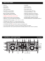
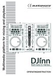
CONTROLS AND FUNCTIONS
30
29
28 27
TOP PANEL
26
25
24
23 22
21
20
1
19
2
18
17
3
16
15
4
5
6
7 8
9
2
10 11 12 13
14
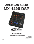
CONTROLS AND FUNCTIONS
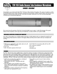
TOP PANEL
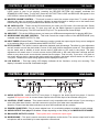
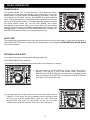
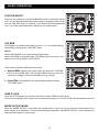
1. SOURCE SELECT BUTTON – This button lets you toggle between USB Port and SD Card slots. This lets
you choose which music source device will play on either side. The LEDs will verify which source is
activated. Glowing green “A” LED signifies USB A port, green “A” LED is blinking signifies CARD A slot;
Glowing red “B” LED signifies USB B port, red “B” LED is blinking signifies CARD B slot. The function can
only be selected under pause mode.
2. MEMORY BUTTON – This button allows you to program up to 4 cue points or 4 loops into the 4 CUE
BANK BUTTONS. The loops or cue point can then be recalled at any time even when the music source
device has been removed and reloaded at a later time.
3. CUE BANK BUTTONS – These buttons are used to store either 4 cue points or 4 loops. Each Bank Button
can store either a loop or a cue point.
4. CUE BUTTON – Pressing the CUE button during playback immediately pauses playback and returns the
track to the last set cue point. The CUE LED will glow when the unit is in cue mode. The LED will also flash
every time a new CUE POINT is set. The CUE button can be held down to momentarily play the music.
When you release the CUE button it instantly returns to the CUE POINT. You can also tap the CUE button
to create a STUTTER EFFECT.
5. PLAY/PAUSE BUTTON – Each press of the PLAY/PAUSE BUTTON causes the operation to change from
play to pause or from pause to play. While in play mode the PLAY/PAUSE LED will glow, and while in pause
mode the PLAY/PAUSE LED will flash.
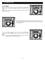
6. JOG WHEEL – This wheel has 3 functions:
y The wheel works as a pitch bend during Playback. Turning the wheel clockwise can increase the pitch
percentage up to 100%, and turning the wheel in the counterclockwise direction can decrease the pitch
percentage down to -100%. The pitch bend will be determined on how long you turn the jog wheel
continuously.
y The jog wheel acts as a slow frame search (1/75 sec) control when the music is not playing but either paused
or set to a cue point. To set a new cue point, spin the wheel then press PLAY or IN when you have
determined the proper position. Press CUE to return to the “CUE POINT”.
y If the search function is active, you will be able to search at a higher speed through all the tracks.
7. MIXED OUTPUT BUTTON – This button is used to switch the output signal between MIXED OUTPUT and
PLAYER 1. When the MIXED OUTPUT is activated, the output will send a mixed output signal. You can
connect the mixed output of the player directly to an amplifier or a set of powered speaker cabinets. If the
MIXED OUTPUT is not activated, the output will send player 1 output signal.
Press the MIXED OUTPUT button for more than 2 seconds to switch MIXED OUTPUT on/off.
8. POWER SWITCH BUTTON – It is used to switch the power on/ standby. When power cord plug into the
rear socket to be the STANDBY mode, all LED are off but STANDBY LED.
(a) In the STANDBY mode, press power button to POWER ON, ” Please insert memory device” is
displayed in the LCD.
(b) In the POWER ON mode, press and hold the power button more than 2sec. to standby.
9. CROSSFADER – This fader is used to blend the output signals of player 1 and 2 together. When the fader
is in the full left position (player 1), the output signal of player 1 will be controlled by the master volume
level. The same fundamentals will apply for player 2. Sliding the fader from one position to another will vary
the output signals of player 1 and 2 respectively. When the crossfader is set in the center position, the
output signals of both the player 1 and player 2 will be even.
10. FADER START SWITCH –used to choose between the external and internal fader starts:
INTERNAL FADER START (Fader start switch UP): the fader start will only react on the crossfader (9)
of the internal mixer. The external CONTROL START input(s) (32) are not active. With this function you
can use the crossfader (9) to start and stop the player. The FADER START switch (10) activates the
fader start feature. When the fader start feature is activated sliding the crossfader from left to right will
play or cue the player connected.
Example: Be sure the Fader Start feature is activated on. Slide the crossfader to the player 1 position
(full left) and begin playback on player 1. Slide the crossfader to the player 2 position (far right), this will
immediately trigger the play function on player 2 and return player 1 to cue mode.
Fader start switch DOWN: the fader start will not work with the crossfader (9) of the internal mixer.
The external CONTROL START input(s) (32) can be used to start/stop the players with mixers that are
compatible with your fader start compatible mixer.
3
CONTROLS AND FUNCTIONS
TOP PANEL
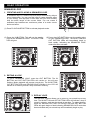
11. CHANNEL EQUALIZER – All of the channels include a two-band signal EQ. These controls are used to
increase or decrease the LOW and HIGH of the output signal. (only available when MIXER OUTPUT is ON)
) HIGH frequency control
This knob is used to adjust the high levels of a channel allowing for a maximum high gain of 10dB or maximum
decrease of –26dB. Turning the knob in a counterclockwise direction will decrease the amount of high
applied to a channel signal, turning the knob in a clockwise direction will increase the amount of high applied
to a channel signal.
) LOW frequency control
This knob is used to adjust the low levels of a channel allowing for a maximum bass gain of 10dB or maximum
decrease of –26dB. Turning the knob in a counter- clockwise direction will decrease the amount of low
applied to a channel signal, turning the knob in a clockwise direction will increase the amount of low applied
to a channel signal.
12. IN BUTTON – This function allows you to set a CUE POINT without music interruption (“on the fly”). This
button also sets the starting point of a seamless loop.
13. OUT BUTTON – This button is used to set the ending point of a loop. A loop is started by pressing the IN
BUTTON. Pressing the OUT BUTTON set the loop ending point. The loop will continue to play until the
OUT BUTTON is pressed once again.
14. HEADPHONE JACK – This jack is used to connect your headphones to the mixer allowing you to monitor
the cue source. Always be sure the CUE LEVEL VOLUME is set to minimum before you put the
headphones on.
15. CUE PAN CONTROL – This functions allows you to monitor the CUE level as well as the Program (main
output) level in your headphones. When you turn the CUE PAN to the full left position, you will only hear
the player signal you playing, on the contrary you will only hear the output signal of the mixer. If the CUE
PAN KNOB is set to the center position, you can cue both the player signal you playing and the output
signal.
16. CUE VOL CONTROL – This knob is used to adjust the headphone volume output level. Turn the knob in a
clockwise direction to increase the headphone volume.
17. PITCH ON/OFF BUTTON –This button has two functions as below:
y This button is used to turn the PITCH SLIDER function on and off. The pitch percentage can be changed
between 4%, 8%, and 16%. 4% will allow the least amount of pitch manipulation and 16% will allow the
most amount of pitch manipulation.
y Press and hold this button for more than 2 seconds to switch the TEMPO LOCK function on/off.
18. PITCH RANGE SELECTOR – Press this button to choose any pitch range percentages of 4%, 8%, and 16%.
19. TRACK KNOB – This knob is used to scroll backward and forward through tracks. Pushing this knob and
turning it at the same time will let you scroll forward or backward 10 tracks per "click" of the knob. Also,
when you press the knob it will toggle between artist, bitrate, title name, genre, and file name of the current
song playing out of the Player.
20. FOLDER KNOB – This knob serves 2 functions depending on which mode you are working in.
(1) Press the FOLDER KNOB will show folder name of the current song playing out of the Player.
(2) Turning the knob will scroll through the folders found on a memory device.
21. BPM/TAP BUTTON – This button is used to override and manually set a track BPM. Occasionally the
built-in BPM meter may not function as desired. This button allows you to override the internal beat clock
and manually set a track BPMs. To manually set the BPMs; tap this button a few times to a tracks heavy
down beat, the unit will automatically calculate your tapping and translate it into a tracks BPMs. The BPM
READOUT is then displayed in the LCD. To return to the automatic BPM counter, press and hold down the
TAP BUTTON for at least 2 seconds and then release.
22. SEARCH BUTTON – This button has two functions:
SEARCH function: Press this button to toggle between fast search (LED lit) and slow search (LED off).
The fast search will automatically turn off if the jog Wheel is not used for more then 10 seconds.
SEARCH mode on – When the SEARCH function is activated you can use the jog Wheel to search
fast backward or forward through the current track whether in play mode or not.
SEARCH mode off – When the SEARCH function is not activated, you can use the jog Wheel to search
frame by frame or a slow search in pause mode and you can use the JOG WHEEL act as a PITCH BEND in
play mode.
Enter the SETUP MENU: Press the SEARCH button for more than 2 seconds to enter system setting mode.
4
CONTROLS AND FUNCTIONS
TOP PANEL
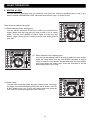
23. RELOOP BUTTON – If a SEAMLESS LOOP has been made, but the Player is not actively in SEAMLESS
LOOP mode (a loop is not playing), pressing the RELOOP BUTTON will instantly reactivate the
SEAMLESS LOOP mode. To exit loop, press the OUT BUTTON. LOOP and RELOOP will appear in the
LCD DISPLAY when the RELOOP function is available.
24. MASTER VOLUME CONTROL – This knob is used to control the master output level. To avoid speaker
damage that may be caused by excessive volume, be sure this knob is always set to the lowest level
before turning the unit on(only available when MIXER OUTPUT is ON).
25. SD CARD SLOTS – These are the SD slots where you insert your SD cards. One card per slot. Gently
insert your SD Card into the slot. To eject your card, put the Media Operator in pause mode, and then
press the SD Card gently. The SD Card should "Pop" out. The preferred file format is Mp3.
26. USB PORT – This is the USB port where you insert your USB mass storage device for playing MP3 files.
27. MICROPHONE VOLUME CONTROL – This knob controls the output volume of the MICROPHONE (only
available when MIXER OUTPUT is ON).
28. INPUT FADER (Channel Fader) – These faders are used to control the output signal of any source assigned
to its particular player (only available when MIXER OUTPUT is ON).
29. PITCH SLIDER – This slider is used to adjust the playback pitch percentage. The slider is a set adjustment
and will remain set until the pitch slider is move or the pitch function has been turned off. This adjustment
can be made with or without a music source device (USB stick or SD card) in the player. The pitch
adjustment will remain even if a music source device (USB stick or SD card) has been removed and will
reflect on any other music source device inserted into the player. That is to say, if you set a +2% pitch on
one music source device, remove that device and insert another, that music source device too will have a
+2% pitch. The amount of pitch being applied will be displayed in the LCD.
30. LCD DISPLAY – This high quality LCD display indicates all the functions, as they are occurring. This
display is viewable at several comfortable angles.
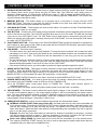
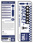
CONTROLS AND FUNCTIONS
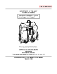
31 32
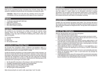
REAR PANEL
34
33
35
36
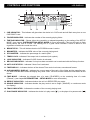
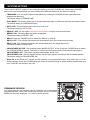
31. AUDIO OUTPUTS – AUDIO OUTPUT from player 2: Output for the audio signal from player 2. Use the
supplied RCA phono leads to connect these outputs to the CD/line input of an external mixing unit.
32. CONTROL START sockets – This remote control is only compatible with certain mixers. If you are using a
mixer with fader start function, use this connector to plug into your fader start compatible mixer.
Attention: Please note that these sockets must never be connected with any voltage.
33. POWER CONNECTOR – Plug in power adapter here. It is a switching adapter to suitable to each voltage.
34. AUDIO OUTPUT from player 1 or mixer –Output depending on the setting of the MIXER OUTPUT MODE.
35. BALANCED OUTPUTS JACKS – These jacks send a balanced output signal.
36. MICROPHONE – This jack is used to connect a microphone to the device. The volume output level for this
microphone will be controlled by its own respective volume knob.
5
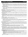
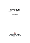
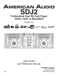
CONTROLS AND FUNCTIONS
1
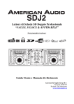
LCD DISPLAY
3
2
4
5
17
6
16
7
8
15
9
14
13
12
11
10
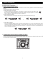
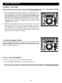
1. CUE INDICATOR – This indicator will glow when the device is in CUE mode and will flash every time a new
CUE POINT is set.
2. FOLDER INDICATOR – Indicates the number of the currently playing folder.
3. TIME BAR INDICATOR – Shows either time remaining or elapsed depending on the setting of the SETUP
MODE. (see chapter SYSTEM SETTING-SETUP MODE for more information) This bar will begin to flash
shortly before the end of a track. The flashing bar is a great visual reminder a track is about to end
regardless of which time mode the unit is.
4. BPM STATUS – This will indicate that the AUTO BPM counter is active.
5. BPM METER – Indicates the BPM value of the currently playing track.
6. PITCH METER – Indicates the percentage of a track's pitch.
7. TEMPO LOCK– Indicates if the tempo lock is activated (lock symbol).
8. LOOP INDICATOR – Indicates if LOOP function is activated.
9. RELOOP INDICATOR – Indicates if a loop has been set which can be activated with the Reloop function.
10. AUTO CUE STATUS – Indicates if Auto Cue is activated.
11. TIME DISPLAY – Indicates the time of the chosen Time mode in minutes, seconds and frames.
12. ALPHANUMERIC DISPLAY– Indicates the current name of the track, of the folder and the sampling rate.
For VBR recorded MP3 tracks the display only show “VBR”. All kinds of other interactive information is also
shown.
13. TIME MODE – Indicates the elapsed time of a track ("ELAPSED") or the remaining time of a track
("Remain"). (see chapter SYSTEM SETTING-SETUP MODE for more information)
14. REPEAT INDICATOR – Indicates whether the unit is in REPEATED play mode.
15. SINGLE INDICATOR – Indicates whether the play mode is set to single ("SINGLE") or continuous mode
(no display).
16. TRACK INDICATOR – Indicates the number of the currently playing track.
17. PLAY/PAUSE INDICATOR – Indicates the device is in play mode (" "), or the player is in pause mode (" ").
6
BASIC OPERATION
SOURCE SELECT functions
1. MUSIC SOURCE DEVICE SELECT
There is a SOURCE SELECT BUTTON to select the music source playback in each PLAYER by your
desires.
You have three different choices as below:
(a) THE SAME CARD PLAYBACK
To play the same card in both player 1 and player 2; insert the card into either SDA or SD
B slot. Press the SOURCE SELECT and both SD A LEDs in the player panel are on when
card is in SD A slot; either does when card is in SD B slot.
(b)TWO CARDS PLAYBACK
Each SD slot inserts a card to play. And each player select different SD slot to play.
or
(c) THE USB PLAYBACK
Press the SOURCE SELECT button and both SD A/B LEDs are on to play the USB device. When
connecting a USB stick, USB card reader, or external hard drive make sure you are correctly lined up
with the USB port and gently insert the USB connection. To disconnect a USB drive, stop playback and
"pull out" the USB connection.
2. CHANGE MUSIC SOURCE DEVICE DURING PLAYBACK
It must in the pause mode, to press the SOURCE SELECT BUTTON you can select the other card. It will
no function when in the play mode.
7
BASIC OPERATION
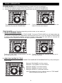
FOLDER KNOB serves 2 functions depending on which mode you are working in:
1. The LCD will display the playing folder name whenever you press the FOLDER knob.
2. You can also search the folders in music source device by turning the FOLDER knob.
The playing folder name will display in the LCD
whenever you press the FOLDER knob.
Turning the FOLDER knob you can search the
folders in music source device.
TRACK KNOB serves 2 functions depending on which mode you are working in:
1. SELECT A DESIRED TRACK
Select a desired track by turning the TRACK KNOB. Turning the TRACK KNOB once will select either the
next forward or backward track; depending on which direction you turn it. If you are using the TRACK KNOB
to select a new track during playback (a track is already in play mode) the new track you selected will
immediately begin playback as soon as the search operation is completed.
Turning the track knob counterclockwise will take
you to the previous track.
Turning the track knob clockwise will take you to
the to the next track.
2. VIEW THE CONTENT OF TITLE
You can view the title content of FILE NAME/TITLE NAME/ARTIST/GENRE/BITRATE by each pressing the
TRACK knob.
Displayed ”FILE NAME” is for file contents
Displayed ”TITLE NAME” is for title contents
Displayed ”ARTIST” is for artist contents
Displayed “GENRE” is for genre contents
Displayed “BITRATE” is for bitrate contents.
Note: Each display for 20 sec. It will auto return to “TITLE NAME”
when no action more than 20 sec.
8
BASIC OPERATION
FRAME SEARCH
This feature allows you to scroll through a track frame by frame,
allowing you to find and set a starting cue or loop point. To use the
scroll function you must first be in Pause Mode or Cue Mode. Once you
are in Pause or Cue mode, turn the JOG WHEEL to scroll through the
track. Turning the wheel in a clockwise direction will advance the frame
search and turning the wheel in a counter-clockwise direction rewinds
the frame search. When you use the JOG WHEEL the monitor
(headphone level) function allows you to hear what you are scrolling
through. Once you reach your desired starting point you can set a cue
(starting) point by pressing the PLAY/PAUSE BUTTON. Pressing the
CUE BUTTON will now return you to the point you just set.
AUTO CUE
This function will automatically set a cue point to the first music note of each track. If a new track is selected, a
new CUE POINT will be set to reflect the new starting point. (see chapter SYSTEM SETTING-SETUP MODE
for more information)
SETTING A CUE POINT
A cue point is the exact point playback will begin when the
PLAY/PAUSE BUTTON is pressed.
A cue point may be created anywhere on a music source device or in a track.
(1) You may press the IN BUTTON on the fly (while the music is
playing). This will set a CUE Point without music interruption.
Pressing the CUE BUTTON will now return you to the same point
that you pressed the IN BUTTON. Pressing the CUE BUTTON will
now return you to this exact point.
(2) You may also use the jog Wheel to set a cue point. While music is
PAUSE or CUE mode, use the jog Wheel to scroll through a track
and find your desired starting point. Once you have found your
desired CUE point press the play Button to set your cue point.
Pressing the cue Button will now return you to this exact point.
9
BASIC OPERATION
SEAMLESS LOOP
1. CREATING AND PLAYING A SEAMLESS LOOP
A seamless loop is a sound loop that plays continuously without
sound interruption. You can use this loop to create dramatic effect
in your mixing. This loop has no time limit and you could actually
loop the entire length of the current folder. You can create a
seamless loop between two continuous points of a music source
device as below:
(1) Press PLAY/PAUSE BUTTON to activate playback mode.
(2) Press the IN BUTTON. This will set the starting
point of the SEAMLESS LOOP. The IN BUTTON
LED will glow.
(3) Press the OUT BUTTON to set the ending point
for your SEAMLESS LOOP. The IN BUTTON and
OUT BUTTON LEDs will immediately begin to
flash rapidly, indicating the SEAMLESS LOOP
mode has been activated.
2. EXITING A LOOP
To exit a SEAMLESS LOOP, press the OUT BUTTON. The IN
BUTTON and OUT BUTTON LEDs will remain on, but will stop
flashing. Music playback will resume normal play. The IN BUTTON,
OUT BUTTON LEDs and RELOOP/LOOP indicator in the LCD will
remain on to remind you that a loop is stored in memory.
3. REPLAY LOOP
The RELOOP function allows you to return to your stored loop at any
time. The IN BUTTON and OUT BUTTON LEDs will indicate a loop is
stored in memory, and may be played at any time. To replay the loop,
press the RELOOP BUTTON. The IN BUTTON and OUT BUTTON
LEDs will again begin to flash indicating SEAMLESS LOOP mode has
been activated and your stored loop will immediately begin to play.
10
BASIC OPERATION
4. EDITING A LOOP
You can edit your seamless loop you obviously must first have created a seamless loop to edit. If you
haven’t created a SEAMLESS LOOP, follow the instructions in step 1 to create a loop.
There are three methods as below:
(1) Edit a seamless loop’s ending point
You can edit the end point of the loop to make your loop shorter or
longer. Make sure the loop that you want to edit is not in reloop
mode. Turn the JOG WHEEL in search mode to make the loop
shorter/ longer. Press the OUT button to set the new ending point of
your loop.
(2) Edit a seamless loop’s starting point
You can edit the starting point of the loop to make your loop shorter.
Under the reloop mode, turn the JOG WHEEL clockwise in search
mode to make the loop shorter. Please make sure the new starting
point must before the ending point. Press the IN button to set the
new starting point of your loop.
(3) Reset a loop
You can reset a new loop under the play or pause mode. Whenever
you find a more desired starting point press the IN button, the LED
of OUT button will go out. Find a new ending point and press the
OUT button to set the ending point of your new loop.
11
BASIC OPERATION
STORING A CUE POINT:
Once you have set your CUE Point, you may store your cue point in one of the CUE BANK BUTTONS.
Either a CUE POINT or a Loop can be stored into a CUE BANK BUTTONS.
(1) Press the MEMORY BUTTON as right Figure. The Memory LED will
glow indicating the store memory function has been activated. You
may now press any one of the 4 CUE BANK BUTTONS to store
your cue point into memory. After pressing one of the CUE BANK
BUTTONS, the corresponding CUE BANK Button LED will flash.
The LED on the CUE BANK BUTTON will turn on and will remain lit
indicating either a loop or cue point is stored in memory. The
MEMORY LED will turn off.
(2) Repeat the above steps to store up to 4 Cue Points. Once your 4
cue points have been stored you may access them at any time.
During playback the cue points will instantly start playback from that
point without any music interruption. Please note in order to access
these cue point, the music source device used to create the cue
points must be in the SD slot or USB port.
TO SAVE CUE BANK POINTS:
To save all your setting into music source device, just press and hold
down the MEMORY BUTTON for about 2 seconds. When the CUE
BANK BUTTONS has been stored properly the LCD will show “CUE
Backup” for about 2 seconds.
RECALL THE CUE MEMORY:
1) Be sure a music source device is loaded into the drive.
2) Press the MEMORY BUTTON so the memory LED turns on.
3) When you select a track or folder the cue point will be loaded automatically, the player will be ready once
the cue points are all loaded. The MEMORY BUTTON LED will flash during recall CUE BANK BUTTONS.
12
BASIC OPERATION
STUTTER EFFECT
When a loop is playing you can press RELOOP button to restart the loop at
once. You can also press this button when a track is not playing in loop. Every
time the RELOOP button is pressed, it will restart the pre-programmed
loop. The stutter effect adds extra creativity to your performance.
TAP BPM
AUTO BPM is the default mode when power on. You can switch Manual
/Auto BPM by pressing the “TAP BPM” button.
Notice:
Switch Manual BPM on just need one touch the button.
Switch Auto BPM on by pressing the “TAP BPM” button more than 1 sec.
and then the LCD will display “AUTO BPM”.
There are two modes for BPM count as below:
1. Manual BPM: following the music tempo and press the “TAP BPM”
button to count BPM value; from the auto BPM to manual mode, the
value won’t change until the correct BPM value is counted.
2. Auto BPM: counting BPM value automatically without pressing
“TAP BPM” button.
TEMPO LOCK
Press the PITCH button for more than 2seconds to switch TEMPO LOCK on/off.
”Pitch Lock” will display when Tempo lock on and 2seconds later icon “PITCH LOCK” will also display in the LCD.
MIXER OUTPUT MODE
When the MIXED OUTPUT is activated, the internal mixer is used. You can connect the mixed output of the
player directly to an amplifier or a set of powered speaker cabinets. If the MIXED OUTPUT is not activated, the
output will send player 1 output signal.
13
SYSTEM SETTING
SETUP MODE
Press the SEARCH button for more than 2 seconds to enter system
setting mode. At this time, LCD display “PRESET” and the SETUP LED
will lit.
Note: System setting will be closed automatically when more than 10
seconds no function.
Turn the FOLDER knob to scroll through the different submenus, you
can adjust the setting by stopping on the desired submenu and pushing
the FOLDER knob.
To exit the system settings, you can turn the FOLDER knob
counterclockwise to PRESET submenu and then press the FOLDER
knob.
NOTE: You can also exit the system settings by more than 10 seconds
no operation and SETUP LED will go out.
14
SYSTEM SETTING
Once enter the SETUP mode you can browse the items by turning FOLDER knob, and pressing FOLDER
knob to on or off item selection, see more details of the different submenus and options as below:
) TIME MODE: You can select different time display by pressing the FOLDER knob to switch between
elapsed and remaining.
The default setting is REMAIN TIME
) PLAY MODE: This function allows you to choose single-track play or continuous track play (all tracks in order).
The default setting is CONTINUOUS play.
) AUTO CUE: This will indicate if the Auto Cue is on or off.
The default setting is AUTO CUE.
) REPEAT: OFF –All the tracks in the music source device will play in the normal mode.
REPEAT: ON –The tracks within one folder are playback.
The default setting is REPEAT OFF.
) RELAY: Press the FOLDER knob to switch the RELAY on and off.
RELAY: OFF –The left and right players will automatically be in the continuous play mode.
RELAY: ON –The left and right players will automatically be in the single play mode.
The default setting is RELAY OFF.
) CROSSFADER ACTIVE: Only available when MIXER OUTPUT is ON. Press the FOLDER knob to switch
the CROSSFADER on and off. This fader is used to mix the output signals of the left and right players.
CROSSFADER: OFF –The output signals of both players will be even.
CROSSFADER: ON –The mix signals from the left and right players according to the crossfader position.
The default setting is CROSSFADER ON.
) Reset all: In the “Reset all?” section, this will reset all your programmed menus and restore the unit to its
default settings. Press the FOLDER knob will return all function setting to default setting automatically and
then "reset OK" will display in the LCD.
FIRMWARE VERSION
You may display the unit firmware version Firmware is the unit internal
programming code. Once enter setup mode and then turn the FOLDER
KNOB until Vxx.xx is displayed. “x’s” are the version number.
15
SPECIFICATION
MODEL:
MPSD-2, USB AND Dual SD Card MP3 Player + Digital Mixer
(compatible with USB mass storage device 1.0/1.1/2.0)
DIMENSIONS:
482 (W) x 132 (H) x 74.8 (D) mm
POWER SOURCE:
DC 6V, 2A
WEIGHT:
2.5 kg
GENERAL:
Display
Pitch control range
Pitch accuracy
LCD
Within +/-4%, +/-8%, +/-16%
+/-0.15 %
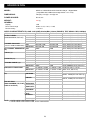
AUDIO CHARACTERISTICS (LOAD: 100K (LINE),600ohm(BAL), 32ohm( PHONES). TEST SIGNAL: MP3, 128Kbps)
ITEM
OUTPUT LEVEL:
(GAIN MAXIMUM, EQ FLAT)
TYPICAL
LINE:
2.1V +/-0.5dB
BANCED OUT 2.1V +/-0.5dB
MIXED OUT: 2.1V +/-0.5dB
PHONES:
0.42V +/-0.5dB
CHANNEL BALANCE:
LINE:
WITHIN 0.5dB
(From 0 to -40dB for MIXED OUT) MIXED OUT: WITHIN 1dB
L/R CHANNEL SEPARATION LINE:
90dB
(*2):
MIXED OUT: 90dB
THD+N (*1):
LINE:
0.007%
MIXED OUT: 0.011%
PHONES:
0.04%
S/N RATIO (*2):
LINE:
93dB
MIXED OUT: 93dB
DYNAMIC RANGE (*2):
LINE:
91dB
MIXED OUT: 85dB
FREQUENCY RESPONSE: LINE:
17-16KHz +/-0.5dB
MIXED OUT: 17-16KHz+/-0.5dB
PHONES MAX. OUTPUT:
1.65V
EQ:
LOW BAND: +6+/-0.5dB
-26 +/-1dB
HI BAND:
+6 +/-0.5dB
-26 +/-1dB
2.2K +/-5%
MIC SECTION:
INPUT
(GAIN MAXIMUM, EQ FLAT, IMPEDANCE:
-36dBV +/-1dB
INPUT
LINE=1V OUTPUT)
SENSITIVITY:
FREQUENCY 20-20KHz +0/-2dB
RESPONSE:
-28dBV
MAXIMUM
INPUT:
S/N RATIO:
80dB
87dB
0.015%
THD+N
NOTE: 1. WITH 20KHz LOW PASS FILTER.
2. WITH 20KHz LOW PASS FILTER, "IHF-A" WEIGHTED.
16
LIMIT
2.1V +/-1dB
2.1V +/-1dB
2.1V +/-1dB
0.42V +/-1dB
WITHIN 1dB
WITHIN 3dB
85dB
85dB
0.02%
0.02%
0.07%
90dB
90dB
85dB
80dB
17-16KHz +/-1dB
17-16KHz +/-2dB
1.4V
+6 +/-1dB
-26 +/-2dB
+6 +/-1dB
-26 +/-2dB
2.2K +/-10%
CONDITION
1KHz, 0dB (TCD-782 TRK.2)
1KHz, 0dB (TCD-782 TRK.2)
1KHz, 0dB (TCD-782 TRK.2)
1KHz, -20dB (TCD-782 TRK.16)
1KHz, 0dB (TCD-782 TRK.2)
1KHz, 0dB (TCD-782 TRK.2)
1KHz, 0dB (TCD-782 TRK.9&11)
1KHz, 0dB (MAX. OUT, EQ FLAT)
1KHz, 0dB (TCD-782 TRK.2)
1KHz, 0dB (MAX. OUT, EQ FLAT)
1KHz, 0dB (1V OUTPUT)
1KHz, 0dB (TCD-782 TRK.2 & 8)
1KHz, 0dB (MAX. OUT, EQ FLAT)
1KHz, -60dB (TCD-782 TRK.18)
1KHz,-60dB(MAX. OUT, EQ FLAT)
(TCD-781 TRK.1, 4 & 16)
(MAX. OUT, EQ FLAT)
1KHz, 0dB, THD=1%
-36dBV +/-2dB
1KHz
100Hz, -20dB(TCD-782 TRK.15)
10KHz, -20dB(TCD-782 TRK.17)
20-20KHz +0/-3dB
-30dBV
1KHz, THD=1%
75dB
82dB
0.05%
1KHz, *2 , NOISE GATE OFF
1KHz, *2 , NOISE GATE ON
1KHz, *2
SPECIFICATION
MP3 FORMAT
SD/USB Format
MP3 Format
File system
Applicable file extensions
Max. number of Folders
Max. number of files
MPEG 1 Layer 3 standard (ISO/IEC 11172-3),
which provides for single channel (‘mono’) and
two-channel (‘stereo’) coding at sampling rates of
32, 44.1 and 48kHz.
MPEG 2 Layer 3 standard (ISO/IEC 13818-3),
which provides for similar coding at sampling rates
of 16, 22.05 and 24 kHz.
MPEG 2.5 Layer 3 standard, which provides for
similar coding at sampling rates of 8, 11.025 and
12 kHz.
17
FAT12/16/32
mp3 . MP3 . mP3 . Mp3
999
max. 999 files
32/40/48/56/80/96/112/128/160/192/224/256/3
20 kbps
Xing/VBRI VBR
32/40/48/56/64/80/96/112/144/160 Kbps
32/40/48/56/64/80/96/112/144/160 Kbps
NOTE
18