1
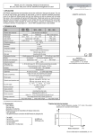
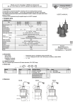
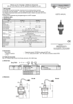
Thank you for choosing NIVELCO instrument.
We are sure that you will be satisfied throughout of its use,
U-200
ULTRASONIC
PROXIMITY SENSOR SERIES
1. APPLICATION
The MICROSONAR proximity sensor works using the ultrasound echo principle and is suitable for measuring
the distances of planar or cylindrical objects.
The measurement can only be accomplished if the space between the unit and the target is free of obstacles
and if the target has good reflection characteristics.
The output of the unit is either an analogue signal depending on the distance, or a distance-controlled switch.
USER’S MANUAL
2. TECHNICAL DATA
2.1 GENERAL DATA
Type
UT-211
Xmin
Xmax
Ultrasound frequency
Total beam angle
Measurement cycle (Tp)
Resolution
Output
Programming
Ambient temperature
Power supply
Consumption Us=12 V
Consumption Us=24 V
Input protection
Integrated cable
Cable core
Electric protection
Ingress protection
Nominal
range
Enclosure
Mass
UR-213
UR-214
UT-212
UTP-261
UTP-262
0.2 m
0.4 m
1.0 m
160 kHz
6.0 m
60 kHz
URP-263
URP-264
5°
25 ms
80 ms
0.1 mm
1.5 mm
0.25 mm
1.5 mm
0.1 mm
0.25 mm
4 ... 20 mA
0 ... 10 V
switch
4 ... 20 mA
0 ... 10 V
switch
Via contact with a PRG cable, or via magnet,
-20 ... +70 °C
10,8 ... 30 V DC
< 55 mA
< 41 mA
< 31 mA*
< 54 mA
< 40 mA
< 30 mA*
< 63 mA
< 49 mA
< 39 mA*
< 61 mA
< 47 mA
< 37 mA*
Reverse polarity, surge, ESD
Shielded cable with PVC coating L = 3 m
4 x 0.5 mm2
Class III
US-2 IP 67, UP-2 IP68
IP 68
US: stainless steel with PP covers,
PP housing (resin mould)
UP: PP Housing
400 g
530 g
Manufacturer:
Nivelco Process Control Co.
H-1043 Budapest, Dugonics u. 11.
Telephone: (36-1) 889-0100 Fax: (36-1) 889-0200
e-mail: [email protected] ♦ www.nivelco.com
* unloaded
2.2 OUTPUT DATA
GND
35V
Voltage rating
Current rating
Residual voltage
Switching delay or
Settling time
Tb**
Temperature error
Linearity error
Repeatability
Output protection
GND
35 V
NPN
GND
Max. 30 V DC
Max. 200 mA
< 2,5 V
U-21-4: 25, 100, 200, 400 ms (a=1, 4, 8, 16) ***
SW38
132
US-21-4
U-26-4: 80, 320, 640, 1280 ms (a=1, 4, 8, 16) ***
A
± 0.35%
1.5 mm
4...20 mA
≤ 500 Ω
(Us > 14 V)
EMC
50
± 0.02% / C
-
1 mm
80
0 ... 10 V
(Us > 13 V)
-
-
≥ 1 kΩ
-
-
M4
68
Pg11
Short circuit, EMC
Short circuit, overload, EMC
* under good reflection conditions ** value of ”a” can be programmed (see under 5.1)
2.3 ACCESSORIES
•
•
User’s Manual,
Certificate of Warranty
• Declaration of Conformity
• Magnetic screwdriver
105
UP-26-4
2.4 ORDER CODE
MICROSONAR
TYPE
Switch
Transmitter
Sensor surface
68
80
Load resistance
GND
104
SW
SW
35V
Max.30
6
Output signal
PNP
2.5 DIMENSIONS
+Us
20
35V
Uout
+
UR-24-4
+Us
28
Output
UR-23-4
+Us
A
UT-22-4
+Us
M30x1.5
UT-21-4
Sensor surface
Type
CODE
R
T
ENCLOSURE CODE
Plastic
P
Stainless steel
S
U
- 2
RANGE
0.2 ... 1 m
0.4 ... 6 m
- 4
CODE
1
6
OUTPUT
4 ... 20 mA
0 ... 10 V
PNP switch
NPN switch
CODE
1
2
3
4
3. INSTALLATION
The unit should be installed stably and in a vibration-free manner, according to
the recommended installation method.
Pipe-enclosure units should be fixed to a mounting plate with a hole of
∅ 31 mm using the nuts supplied to nold the plate in the middle. Units with flat
enclosure can be mounted to the wall or any flat surface laid on its backside,
using the four nuts. Cables should be free of tension and LEDs should be
visible.
In case of limited space, the path of the ultrasonic beam may be redirected by
a metal sheet as below (Figure1).
Figure 2 shows the distance (e’t) within which the unit senses the target as well
as the distance (e”t) outside of which disturbing objects do not disturb the
operation of the unit. Units with the same frequency may mutually disturb each
other as sent or reflected ultrasound may reach the other unit. To avoid such
interference, units with parallel axes should be installed outside of the minimum
distances as per Figure 3. Greater minimum distances might be required for
applications with targets with round reflecting surfaces (like pipes) that involve
side reflections.
4. WIRING
Wiring should be carried out in accordance with Figure 4 and Figure 5 taking
into consideration the colour of the wires as per Table 1.
A
diverting sheet
UR/UT-200
.
+10.8...30V DC
+Us
+10.8...30V DC
+Us
+
SW / OUT
NPN
switch
SW / OUT
Rt
PRG
GND
GND
B
A
Figure 4
Wiring during programming
Type
∅dt
Xt
Target
Sensor
e''t
e't
UT-21-4
UT-22-4
Surface detected
Indefinite half sheet
UR-23-4
UR-24-4
U -21
Curve of disturbance
10
0
20
40
60
80
100
X t [cm]
Colour*
+US
brown
IUOT or UOUT
green
PRG
white
GND
yellow
shielding
blue
+US
brown
SW
green
PRG
white
GND
yellow
shielding
blue
5. COMMISSIONING, OPERATION AND PROGRAMMING
5.1 COMMISIONING, OPERATION
Following the power up, the unit will run a self-test routine for 5 seconds.
During the self-test all three LEDs are lit. In the event of a failure all the LEDs
will blink at the same rate.
Interpretation of the LED states during proper operation:
Curve of disturbance
0,6
0,4
d t = 50
Green: Blinks at the rate of the measurement.
(lights continuously at high frequencies)
80 [mm]
0,2
Yellow: Lights up continuously in the case of valid echo.
0
0
1
2
3
4
5
6
X t [m]
Figure 2
Limits of disturbance and sensing
Bmin
Cable
Table 1
Cable colours
U-26
et
[m]
Figure 5
Wiring during operation
* The grey cable with isolated ending is only for service purposes
d t = 13 [mm]
0
GND
shielding
B
Figure 1
Redirection of the ultrasonic beam using a reflective surface
et
[cm]
20
GND
shielding
A + B > x m in
Surface detected
+
PNP
switch
or
analogue
PRG
Red:
Lights up if the unit senses a disturbance signal within the minimum
measuring range (e.g. bad installation) or if the target is too close.
In this case an error will be indicated by the output
The UR-23-4 devices compare the measured distance with the two
pre-programmed (XA and XB) distances and switch in accordance with Figure 6.
1.5 Bmin
U -21
U -26
Bmin [m]
0.25
0.75
XA < X B
closed
closed
open
open
XA
Figure 3
Minimum distance of units working parallel next to each other
XA > X B
XB distance
XB
Figure 6
Transfer characteristic of units with switch output
X A distance
Within the two pre-programmed distances the output signal of the UT-21-4
and the UT-22-4 transmitters are proportional to the distance in
accordance with Figures 7 and 8.
XA < X B
I out
I out
20.5 mA
20 mA
20 mA
XA > XB
20.5 mA
3.8 mA
3.8 mA
4 mA
4 mA
XA
XB
distance
XB
XA
distance
Figure 7
Transfer characteristic of units with current output
XA < X B
Uout
Uout
10,5 V
10 V
10 V
XA > X B
10,5 V
< 20 mV
UT >13V
< 20 mV
XA
XB
distance
XB
XA
distance
Figure 8
Transfer characteristic of units with voltage output
After the first power up the unit will work with the factory settings and
afterwards the characteristic configuration is as can be seen below:
SWITCHES: XA = Xmax/2, XB = XA + 0.1 m
TRANSMITTERS: XA = Xmin, XB = Xmax
Distance parameters XA, and XB can be changed by programming by placing a
good reflecting target at the distance to be programmed and by selecting the
relevant menu. The unit will measure and store (learn) the distance.
MICROSONAR receives the echo coming from the nearest reflecting surface
within the range. The range of the unit with Factory Setting is between Xmin and
Xmax. (Nominal range)
If the target is moving within smaller range it is advisable to reduce the range
by far-end blocking which should be done by programming the limit of XT.
Factory default XT = Xmax
Sensor surface
2
Targets
present
1,2,3
2,3
3
3
1
0 Xmin
A X1
X2
XB XT
error (caused by noise). On the other hand this will cause a speed-dependent
target tracking error which diappears after a a⋅Tp settling time or switching
delay
Number of discarded echoes: k (1, 3, 5, 10)
Under disadvantageous conditions (air movement, not perpendicular or bad
reflecting surfaces) some of the echoes may miss the sensor. Paying
immediate attention to this, might lead to frequent error indication and big
measurement errors. Therefore the unit first checks the measured distance to
verify that it is within range.
Measured distances outside the range will be disregarded during average
calculation and the output signal maintains the former value. The unit can
disregard k number of consecutive distance samples before an error will be
indicated.
If due to bad reflection a substantial number of echoes are lost and the number
of invalid (incorrect) echoes between two valid ones, is smaller than k the unit
will maintain the output signal continuously. The greater the programmed value
of k, the less sensitive the unit will be to invalid echoes but the reaction time for
error indication will increase. To maintain continuous operation the
programmed range should be kept as narrow as possible (with far-end
blocking).
The greater the speed of the target the smaller the chosen averaging number
should be. The worse the reflection of the target the higher the chosen value of
k (number of discarded echoes) should be.
5.2 PROGRAMMING
1. Touch-Magnet Programming
The magnetic screwdriver (with its cap removed) should be used to touch the
points on the enclosure marked A or B according to Figure 10. These steps
will hence be indicated as A or B.
Touch-Magnet Programming is only possible if it is not disabled and the PRG
wire is free. Disabling can be programmed by both Touch-Magnet
Programming or by cable contacting, but it can only be undone by cable
contacting.
Measured
distance
X1
X2
Error
Xmax
Figure 10
Position of the magnetic screwdriver during programming
Figure 9
Far-end blocking will prevent evaluation of echoes beyond XT. Should the echo
be lost for any reason (unstable echo, intensive movement of air), the object
behind XT will not be taken into consideration but an error will indicate the lack
of a valid echo.
Error indication at the output of different units:
SWITCH STATUS: off (open)
TRANSMITTER IOUT = 3.6 mA
TRANSMITTER UOUT = 0 V
The signal processing of the unit can be adapted to the most diverse
requirements and conditions of an application. The two programmable
parameters influencing signal processing are the averaging number and the
number of discarded echoes.
2. Programming via cable contact
The steps A or B can be realized by connecting the PRG wire to +US or GND
respectively.
This can be done by using either the switch or two push buttons connected
for the period of the programming, or by simply connecting the ends of the
cables.
Different states in the programming procedure are indicated by the three LEDs.
Steps A and B (magnet touch, wire connection) should be maintained till the
effect will be indicated by the relevant change of the LED status.
off
on
blinking
Red
LED
Yellow
LED
Green
LED
Red
Yellow Green
Averaging number: a (1, 4, 8, 16)
To reduce random measurement errors the unit will not provide output on the
basis of a single measurement but by taking the average of the last a number
of distance samples.
Increasing the averaging number reduces the small fluctuation of the output
signal caused by the uncertain movement of the target or by measurement
Figure 11
Arrangement of the LEDs and LED state interpretation in the manual
hold > 2s
A
wait
5s
B
B
A
5s
A
B
B
A
5s
B
X Learning
1.
Switch off, 4 mA, 0 V
X Learning
2.
Switch on, 20 mA, 10V
X Learning
3.
Far-end bloking
A
a=1
a=4
a =8
B
B
B
a = 16
5s
B
B
4.
Averaging
number
A
k=1
k=3
5s
A
B
B
A
disabled
Measurement
A
Select
Menu Point
k = 10
A
B
B
B
5.
Number of
discarded
echoes
enabled
5s
B
k=5
A
A
B
6.
B
Enabling Touch-Magnet
Programming
Completed
Figure 12
Procedure of the programming
A
Invalid echo
Measurement
Measurement
Learning accepted
Figure 13
Indication while learning
To enter programming mode: hold step A for 2 s
To quit programming mode: hold step B
Once in Programming mode, the red LED will start blinking, and the yellow
and green LED s go off.
While in programming mode (with the red LED blinking) every step A will
move the device to the next Menu item. The six different Menu items are
indicated by a combination of the states of the yellow and green LEDs.
About 5 seconds after selecting a Menu item and if there is no step A or B,
then the unit will automatically start to execute the menu item. In this case, the
red LED goes on continuously. In the first four Menu Points learning should be
initiated by step A. Blinking of the green LED indicates measurement during
learning. On getting a valid echo the yellow LED will light up and the relevant
numeric value of the measured distance appears on the output (for instance
with measured distance of 0.4 m the output will be 0.4 mA or 0.4 V!) With
repeated step A a new distance can be learnt and the old one will be
overwritten. Step B will finalise learning and result in return to the Menu item
selection. Another Step B will make the device quit Programming Mode.
Parameters a and k can be programmed using Steps A and B in Menu item
4 and 5
Touch-Magnet programming can be enabled or disabled in Menu item 6 using
step A. Disabling of the Touch-Magnet Programming by the use of the magnet
will be completed after quitting Programming Mode.
During Touch-Magnet Programming the Wire-Contact Programming is
disabled and vice versa.
If the unit is left in Programming Mode for more than 10 seconds, it will quit
automatically. After programming is done connect the PRG wire to the GND.
Loading factory settings
Disconnect the unit's power supply. Before powering on again, connect the
PRG wire to the +Us. After powering on first the green, then the yellow and
then the red LEDs will start blinking one after another. Wait until all three LEDs
stop blinking and disconnect the PRG wire from +Us. The device will now
measure using the default factory settings. Reconnect the PRG wire to the
GND.
In a very noisy environment, before powering on, make sure that the PRG wire
is connected to the GND, otherwise on powering on, the device may load the
default factory settings.
Example: assignment of XB
Place a target at a distance (XB) from the unit to which you want to assign
20 mA or 10 V or to trigger the switch-on. In the distance learning procedure,
XT will be disregarded.
Hold the magnet to point A till the red LED begins to blink (we are now in the
first menu item in the Programming Mode). Remove the magnet and hold it to
point A again to step to the second Menu item. The red LED will be blinking,
the yellow one will go off and the green one go on (we have now stepped to
the second menu item). Remove the magnet and wait (approximately 5s) until
the red LED goes on continuously. (ready for learning). Hold the magnet again
to point A (learning started). The green LED starts to blink (representing
measurement) then goes off (measurement completed) and the yellow LED
will light up for a short time (implying valid echo). After the learning process
has been completed the green LED goes off. Then place, remove and place
the magnet to point B again to quit the menu item selection and Programming
Mode respectively.
6. MAINTENANCE, REPAIR
The unit does not require maintenance on a regular basis. In some very rare
instances however, the deposited material on the transducer may need to be
cleaned from the echo surface. This must be carried out gently, without
scratching or pressing or hitting the surface of the transducer.
Repairs beyond the warranty period have to be carried out exclusively at the
Manufacturer’s premises. Equipment sent back for repair should be cleaned or
neutralised (disinfected) by the User. Proof of this should be documented in
writing during handover.
7. STORAGE
Ambient temperature:
Relative humidity:
-20...+70 °C
max. 98%
8. WARRANTY
Nivelco provides warranty for the period of 2 (two) years.
All repairs under warranty are performed in the Manufacturer's premises.
Warranty claims are only valid with upon presentation of both the manual and
the invoice. Cost of dismantling, reinstalling and transportation are borne by
the Customer.
Warranty claims are not valid in the event of damages during transportation,
failures due to abnormal usage, breakage, natural disasters, or incompetent
installation or operation.
urp2634a0600h_02
May. 2007.
Nivelco reserves the right to change technical specifications without notice.