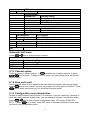
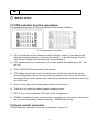
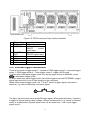
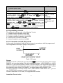
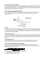
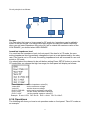
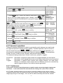
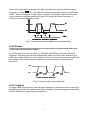
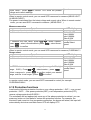
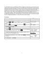
1
3) When select bus trigger mode, first set the trigger source as BUS, connect the
electronic load by GPIB or USB or GET communication interface, then if get the *TRIGG
command, the load will produce a trigger signal.
4) When select timer trigger mode, first set the trigger source as TIMER, set the TIGGER
TIMER's time,the load will produce a singal from time to time.
5) When select hold trigger mode, first set tirrger source as HOLD, the load will produce
signal when get the TREG:IMM command.
Pin 2 will output corresponding trigger signal whatever trigger mode you choose.
5.4.2 External ON/OFF control connection
31
1
8
Figure 5-6
ON/OFF IN is used to control the multi-channel to take load or unload synchronizelly.
When ON/OFF IN pin receives a low pulse, ON/OFF state of load will reverse. If SYNC
ON SET of a specific channel is set ON, then you can use figure 5-6 connection to control
its ON/OFF state.
ON/OFF OUT indicates ON/OFF state of multi channels electronic load. If SYNC ON SET
of any specific channel is set on, and the channel’s input state is on, the pin 4 output low
level, otherwise it output high level
5.5 Extended frame connections
The following section introduces extended function of IT8702 mainframe:
Extended mainframe
interface
Figure 5-7 Expand interface
This interface can be used to connect extended frame. IT8700 can take up to 16
channels with extended frame.
Procedure: Use expand cable to connect mainframe and expand interface of extended
frame. Enable expand function in the menu of IT8702 mainframe by pressing Shift
+
4
, select “Expand modul”, choose ON.
37