1
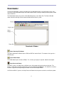
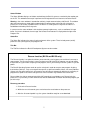
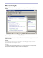
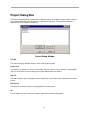
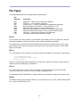
Version 2.0
1998-2002 by NetMedia, Inc. All rights reserved.
Basic Express, BasicX, BX-01, BX-24 and BX-35 are trademarks of NetMedia, Inc.
2.00H
2
Contents
1. Downloader...............................................................4
2. Editor and compiler.........................................................8
3. Project dialog box ........................................................11
4. BX-01 chip dialog box ......................................................13
5. BX-24 and BX-35 chip dialog boxes ...........................................16
6. Watch window ...........................................................18
7. Tutorial on using the watch window ...........................................20
8. File types ...............................................................23
9. Command line operation ....................................................26
3
Downloader
The BasicX Downloader is where executable files are downloaded and run on the BasicX system. You
can also use the Downloader to open the Editor/Compiler when creating or editing the BXP project or BAS
source code files.
The Downloader displays the results of the download process in the Status Bar. The Status Window
allows interactive two-way RS-232 communication with the BasicX system.
Downloader Window
Open Download File Button
The Open Download File Button loads a BXB and PRF file into the BasicX. The button will ask you for a
BXB filename.
Open Editor Button
The Editor Button opens the BasicX Editor. This is where your project is opened, edited and compiled.
Stop Processor Button
On BX-01 systems, the Stop Processor Button turns off the power derived from the parallel port. The
button is useful when changing components on the Developer Board. Warning -- this button has no effect
on power supplied externally through the Power Port on the Developer Board.
On BX-24 and BX-35 systems, the Stop Processor Button halts the processor but has no effect on power.
4
Execute Button
The Execute Button tells the BasicX program to boot up and start running. This is indicated when the
Status Bar says RUNNING. The Execute Button has the same effect as physically releasing the Reset
Switch on the Developer Board.
Reset Processor Button
The Reset Processor Button halts BasicX program. This is indicated when the Status Bar says RESET.
The button has the same effect as physically pressing the Reset Switch on the Developer Board, but the
(software) button takes precedence over the physical switch.
Download Program Button
The Download Program Button loads a BXB file into the BasicX system.
Clear Serial Window Button
The Clear Serial Window Button clears the contents of the Status Window.
Downloader Menus
File Menu
The File Menu allows you to open BXB and PRF files, or exit the BasicX Development Environment. The
BXB files are BasicX binary executables created by the compiler, and PRF files contain additional
information needed by the BXB file.
Open Download opens user-specified BXB and PRF files. After you open the files, you use the Download
button to load the program into the development system.
Set Starting Directory allows you to specify the directory where the program initially looks for project files
to open.
5
Capture File Window
The Capture to File menu choice allows you to record data received by the monitor port on the PC. The
data is stored in a user-specified file, which has a length limited only by available disk space. Recording
continues until you close the file or exit the program.
Processor Menu
The Processor menu allows you to select which BasicX system type to use. Choices are BX-01, BX-24
and BX-35.
I/O Ports Menu
The I/O Ports menu allows you to configure communication ports. Download Port configures the port used
for downloading programs to the BasicX. The download port may be either a parallel or serial port,
depending on the BasicX system being used.
If a serial port is used for downloading, you select only the com port number. Other settings, such as baud
rate and parity, are fixed and cannot be changed by the user.
Monitor Port configures the serial port that is connected to the status window. Here you can specify the
PC’s com port number, baud rate, parity, number of data bits and number of stop bits.Note that the
monitor port is bidirectional -- data received from a BasicX is displayed in the status window, and data you
type into the status window is transmitted to the BasicX.
Note that for systems that use serial downloading, the monitor port can be the same as the download port.
The program switches between the 2 modes automatically.
The Rescue function (BX-24 and BX-35 only) forces the processor to accept a new program (see page 7
for more detail).
Progress Bar
The Progress Bar displays the percentage of completion when downloading your program into the BasicX
system.
6
Status Window
The Status Window displays serial data received from the BasicX system as received by the monitor port
on the PC. This window also accepts input from the PC keyboard for serial transmission to the BasicX.
Warning -- the status window is intended for relatively simple communications with BasicX. The window
does not incorporate any handshaking protocol when it communicates with a BasicX serial port. In
practice, this is not usually a problem unless the BasicX is sending data at a high rate and the PC is
loaded down with other processing tasks.
In some cases the status window is able to detect communication errors, such as overflow of its input
buffer. If an error is detected, the message "Serial Data Error Detected" is displayed to the right of the
Progress Bar.
Status Bar
The Status Bar indicates the status of various elements of the system. These include power (on/off),
processor state (running/reset) and program size.
Title Bar
The Title Bar indicates the BasicX Development System version number.
Rescue function (BX-24 and BX-35 only)
The Rescue function is an option that allows you to override a running processor and force it to accept a
new program. The Rescue function is necessary because a BX-24 or BX-35 program can go into modes
that prevent the system from accepting a new program, even if you manually reset the system or cycle the
power.
The BasicX Operating System needs to see the serial port in order to accept a new program. Anything
that interferes with this, such as turning off interrupts for a significant amount of time, can cause problems.
System calls PulseOut and PulseIn, for example, turn off interrupts temporarily while they'
re executing. A
program that spends a lot of time calling these or similar functions may need the Rescue function.
Rescue allows the chip to communicate within 0.25 seconds of a pushbutton reset. Rescue halts the
processor in a special way so it will communicate with the downloader no matter what kind of program you
put in the chip.
Recovery procedure:
1. Click on the Rescue function
2. Within the next 10 seconds, press and release the reset button on the processor.
3. After the 10 second period is up, the system should be ready for a new download.
7
Editor and Compiler
The BasicX Editor/Compiler is where your project and its accompanying files are opened, edited and
compiled.
Title Bar and Tabs
Editor Window
The Title Bar displays the project currently open. The tabs and nested windows display the names of each
module being edited.
File Menu
The File Menu opens and saves project and module files. Each BXP project file keeps track of the
collection of modules that make up each program.
Edit Menu
The Edit Menu allows various editing operations, such as cut, copy, paste, search and replace. Rightclicking the mouse also displays a popup menu with several editing options.
8
Compile Menu
The Compile Menu has options for compiling and running the project. Compile creates a BXB executable
file. Compile and Run creates the file, downloads it to the BasicX and starts the program running. Compile
Status displays the status of the last compile, including compiler error messages, if any.
Options Menu
In the Options menu, the Processor choice allows you to select which BasicX system type to use. Choices
are BX-01, BX-24 and BX-35 (this menu item is a duplicate of one in the downloader window).
The Environment choice opens a window (below) that allows you to control various environment settings.
Various editor settings are available in the Editor Options tab, including tab width, font size and font type.
Syntax highlighting is controlled by user-selectable colors for code, comments and string literals.
Environment Window
In the Project Options tab, you can specify that changes are automatically written to disk whenever you
compile a program. Or you can have the compiler ask whether you want to save changes.
You can also specify the following 3 compiler settings:
Code optimizer
This checkbox allows you to control whether the compiler optimizes the program.
Optimization generally reduces the size of a program.
Strict syntax rules
This checkbox enforces various coding restrictions intended to make code easier to
read and understand. The restrictions affect for-next loop counters, numeric literals
and bitwise logical operations. See the language reference manual for more details.
9
Maximum string length
This textbox allows you to specify the maximum allowable length of both
variable-length and fixed-length strings. The selectable range is 1 to 64
characters, with a default of 16 characters.
Since all variable-length strings require the same amount of storage, you
can reduce overall storage requirements by selecting an optimum value
for the string size.
Project Menu
The Project Menu has choices that affect the project. Chip opens the Chip Dialog Box with options to
make common setup routines easier, such as defining the initial states of I/O pins. The Files choice opens
the Project Dialog Box, which allows you to add or delete modules in the project. Watch Window allows
you to watch variables in a running BX-24 or BX-35 program.
Window Menu
The Window menu allows you to specify how nested windows are displayed in the editor. Choices are
Cascade, Tile Horizontal and Tile Vertical.
Edit Window
The Edit Window is where the code for the module files are created and edited. At the bottom of the edit
window is the Status Bar:
Status Bar
The Status Bar indicates the status of various elements of the system. Panel 1 indicates the line and
column number of the text cursor. Panel 2 shows whether the text cursor is in insert (INS) or overlay
(OVR) mode.
Panel 3 indicates whether errors or warnings were generated by the compiler. Panel 4 shows whether or
not the compile was successful.
If the compile was successful, panel 4 displays the amount of EEPROM memory used by code, the RAM
allocated to static variables, and the nonvolatile memory allocated to persistent variables (abbreviated
PRS). If the compile was not successful, a fatal error message appears in this panel.
The above information can also be viewed in a separate window by clicking on the Status Bar or choosing
Compile Status under the Compile Menu. You can also see more details of memory allocation by looking
at the MPP map file, which is created whenever you compile a program.
Warning – the RAM memory in the Status Bar applies only to memory allocated to static variables. This is
not the same as the total amount of RAM required by a program. In particular, task stacks need additional
RAM, which is not displayed here.
10
Project Dialog Box
The Project Dialog Box keeps track of source code that makes up the project. Source code is stored in
one or more module files, each of which has a default BAS extension. The collection of modules is
compiled into the final BXB executable file.
Project Dialog Window
Title Bar
The Title Bar displays the BXP filename of the currently-open project.
Project Files
The Project Files textbox lists all files in the project. Each file contains source code for a single module.
You can select which files to include by pressing the Add/Remove Files buttons.
Add File
The Add File button opens a dialog box where module files can be chosen to be added into the current
project.
Remove File
The Remove File button removes the highlighted file from the project.
OK
The OK button exits after saving any changes made within the Project Dialog Box.
11
BX-01 Chip Dialog Box
The Chip Dialog Box allows you to control BasicX chip options such as external RAM, COM1/COM2 serial
ports, internal SPI, SPI size and extended I/O. You can set network options such as baud rate and
node/group address. You can also control the initial state of each I/O pin (note that some of these options
can also be controlled by the BasicX program itself).
External RAM
The External RAM option configures BasicX to utilize the additional RAM of the RamSandwich . External
RAM requires pins 2, 16, 17, 21-28, and 32-39.
Cache
The Cache option can be enabled when External RAM is utilized. When checked, it loads your program
into memory where it will run faster.
12
COM1
The COM1 option configures BasicX to utilize the built-in COM1 device. This disables the network. COM1
requires pins 10 and 11.
COM2
The COM2 option configures BasicX to utilize the built-in COM2 device, which requires pins 1 and 12.
Extended I/O and RAM
This option configures BasicX to utilize an external device such as the Video-X . Extended I/O requires
pins 3, 21-28, and 32-39.
SPI code storage
The SPI Code Storage defines the maximum allowable program space available in the chip. The compiler
checks to make sure your program fits in this memory.
Internal EEPROM
The Internal EEPROM option determines whether your program is downloaded internally to the BasicX
chip, or externally to another SPI chip. External SPI requires pins 6, 7, and 8. Checking this box selects
internal SPI and frees those 3 pins.
Network Enable
The Network Enable option configures BasicX to utilize the built-in network feature. The network requires
the COM1 device and pins 10, 11, and 14.
Node Address
The Node Address sets the network address node for the processor. Each chip on a particular network
must have a unique address. Valid node addresses are in range 0 to 65 279.
Group Address
This option allows you to define the group address of the chip. Multiple nodes on a network are allowed to
share a common group address, and groupcasting allows you to send a network packet simultaneously to
all members of a particular group. Valid group addresses are in range 0 to 254.
Baud Rate
The Baud Rate sets the network communication rate. The maximum (and default) is 460 800 baud.
13
OK Button
The OK Button exits after saving any changes made within the Chip Dialog Box.
Cancel Button
The Cancel Button exits and disregards any changes made within the Chip Dialog Box.
I/O Pin Grid
The I/O Pin Grid allows you to define the initial state of each available I/O pin whenever the processor is
rebooted. Each pin can be set to one of four states -- tristate, pullup, output-high and output-low:
IN Input -- Configures the corresponding pin as a tristate (high impedance) input. Typically 5 V is logic
high (on 5 V systems) and 0 V is logic low.
P Input w/Pullup -- Configures the pin as an input with pullup. This state is typically used to sense the
state of passive devices such as switches.
0 Output Low -- Configures the corresponding pin as a logic low output, which is 0 V.
1 Output High -- Configures the pin as logic high output, which is typically 5 V.
The I/O Pin Grid defines only the initial states of each pin. After startup, you can also have the program
configure each pin independently using procedure PutPin or other system calls.
Known Bugs
If you enable the cache option, the program will occasionally fail to start after download or reset. A
workaround is to disable this option.
14
BX-24 and BX-35 Chip Dialog Boxes
The BX-24 and BX-35 Chip Dialog Boxes allow you to control the initial state of the I/O pins and on-board
LEDs on a BX-24. These options can also be controlled by the BasicX program.
I/O Pin Grid
The I/O Pin Grid allows you to define the initial state of each available I/O pin whenever the processor is
rebooted. Each pin can be set to one of four states -- tristate, pullup, output-high and output-low:
IN Input -- Configures the corresponding pin as a tristate (high impedance) input. Typically 5 V is logic
high (on 5 V systems) and 0 V is logic low.
P Input w/Pullup -- Configures the pin as an input with pullup. This state is typically used to sense the
state of passive devices such as switches.
0 Output Low -- Configures the corresponding pin as a logic low output, which is 0 V.
1 Output High -- Configures the pin as logic high output, which is typically 5 V.
The I/O Pin Grid defines only the initial states of each pin. After startup, you can also have the program
configure each pin independently using procedure PutPin or other system calls.
15
OK Button
The OK Button exits after saving any changes made within the Chip Dialog Box.
Cancel Button
The Cancel Button exits and disregards any changes made within the Chip Dialog Box.
LEDS Box (BX-24 only)
The LEDS box allows you to define the initial state of each of the two LEDs on the BX-24. You can also
have your program control the state of each LED through pin I/O functions -- the red LED is connected to
pin 25 and the green LED is connected to pin 26. To turn on an LED, you need to set the pin to logic low.
Raising the pin turns off the LED.
16
Watch Window (BX-24 and BX-35 only)
The Watch Window allows you to watch variables in a running BasicX program. The Watch Window can
handle static (module-level) variables in RAM memory. Variables can be numeric or Boolean types. If an
array is chosen, the first element of the array is displayed:
Watch Window
The Watch Window is chosen from the Project menu in the editor.
The upper window lists RAM-based module-level variables in the program. The checkboxes allow you to
select which variables to watch. The lower window displays the current values of the selected variables.
The Watch Window periodically polls the BasicX processor to update each variable. The combo box at the
bottom of the window allows you to tailor the sample rate by selecting from sample periods ranging from 1
second to 5 seconds.
The Watch Window reads the BXM file, which is generated whenever a program is compiled. See the next
section for details about the contents of the BXM file.
17
Warning -- the Watch Window requires the BasicX processor’s Com1 serial port in order to communicate.
The program should not use Com1 while the Watch Window is active, and the monitor port should be
closed.
Also, anything that inteferes with serial communications, such as turning off interrupts, will interfere with
the Watch Window.
The following variables and objects are not displayed in the watch window:
Local variables
Persistent variables
String variables
Register objects
Block data objects
18
Tutorial on using the Watch Window
Procedure
To illustrate the Watch Window, we'
ll use the following program as an example. The objective is to display
the value of static variable i while the program is running:
Dim i As Integer
Sub Main()
i = 1
Do
i = i + 1
If (i > 5) Then
i = 1
End If
Call Delay(2.0)
Loop
End Sub
To start the Watch window, the first step is to open the editor and make sure BX-24 or BX-35 is selected
in the Options-Processor menu:
Processor Type window
19
The next step is to compile and download your program as usual. Once the program starts running, select
the Project-Watch Window menu:
Project-Watch Window menu
20
The Watch Window should appear. In the top window, you can choose one or more module-level
variables to watch, and the compiler will dynamically update the values of each variable on the bottom
window. Note that the variable type is displayed next to each identifier in the top window:
Watch Window
In this case, the variable test.i is updated about once per second. The update rate can be chosen from the
combo box at the lower edge of the window.
21
File Types
The compiler/downloader reads and generates the following files:
File
Extension
Description
BAS
BXP
PRF
BXB
MPP
BXM
MPX
OBJ
ERR
Module file -- contains source code for the program.
Project file -- lists all modules in program.
Preferences file -- contains initialization and configuration information.
BasicX program in binary format -- similar to EXE file on a PC.
Map file of entire program, in human-readable format.
Map file of static module-level variables, in machine-readable format.
Map file of module level variables, in source code format for network.
Object file -- contains object code for each subprogram
Error log file, produced by command line mode
BAS file
This file contains the source code for a single module. Each module must be in a separate file, with one
and only one module per file. File extensions can be arbitrary, with BAS as the default.
The module name is taken from the filename without the extension. The module name must be a legal
Basic identifier, which means the name must start with a letter, and all other characters must be letters,
digits or underscores.
BXP file
This is the project file, which contains a list of the filenames of all modules in the program. Typical format:
C:\Dir1\MainModule.bas
C:\Dir3\SubDir\Irrigation.bas
SerialPort.bas
Filenames are prefixed by optional pathnames. If a pathname is absent, the compiler assumes the file is
located in the same subdirectory as the BXP file.
PRF file
This is the preferences file, which contains information required by the BasicX system. Information
includes the initial states of I/O pins, as well as memory configuration data.
The combination of PRF and BXB file is required whenever you download a program to a BasicX system.
BXB file
The BXB file contains the executable code that is run by the BasicX chip. This file, combined with the PRF
file, is similar to the EXE file on a PC.
22
MPP file
This file contains a map of the entire program. The following categories are listed:
Module-level RAM variables
Persistent (EEPROM) variables
Subprogram local data
Code memory (subprograms and block data)
BXM file
The BXM file contains a description of all module-level (static) variables and arrays in the program. The
file is in machine-readable ASCII text format. Each line in the file contains the following data in comma
delimited format:
ModuleName.VariableName -- Module name and variable (or array) name in quotes, using dot
separator.
MemoryLocation -- Address of the start of the variable.
DataType -- Data type enumeration (see below).
IsPersistent -- Whether variable is persistent. Value is #TRUE# or #FALSE#
Dimensions -- Number of dimensions. Scalar is zero.
The lower and upper bound of each dimension is listed for all eight possible dimensions. For string
variables, the first upper bound is the maximum number of characters that can be stored in the
string.
Data type enumerations:
Type
Value
UnsignedInteger
Byte
Integer
Long
UnsignedLong
Single
Boolean
String
17
18
19
20
21
32
50
61
Example -- assume the file SerialPort.bas contains the following module-level declarations:
Private Const InputBufferSize As Integer = 32
Private InputBuffer(1 To InputBufferSize) As Byte
The BXM file contains this line:
"serialport.inputbuffer",400,18,#FALSE#,1,1,32,0,0,0,0,0,0,0,0,0,0,0,0,0,0
23
Decoded values:
ModuleName:
VariableName:
MemoryLocation:
DataType:
IsPersistent:
Dimensions:
LowerBound(1):
UpperBound(1):
LowerBound(2..8):
UpperBound(2..8):
"serialport"
"inputbuffer"
400
Byte (18)
False
1
1
32
0
0
MPX file
This file contains information about module-level variables in source code format. The primary function of
the MPX file is to provide information to a remote node on the network in order for the remote node to get
read/write access to static variables on the local node.
In the above serial port example, the MPX file contains the following lines pertaining to array InputBuffer:
' serialport_inputbuffer data type: Byte
Public Const serialport_inputbuffer As Integer = 400 ' &H190
Public Const serialport_inputbuffer_IsPersistent As Boolean = False
You can include the MPX file directly as a module in the remote program. Whenever you change the local
program, the MPX file is updated automatically when you compile the program, which means you can
recompile the remote program to update it.
Note -- the address of each variable has a numerical range of 0 to 65 535. However, the MPX file uses
16-bit signed integer types in which to store these numbers, and addresses between 32 768 and 65 535
are actually represented as negative numbers in two'
s complement format. The internal bit patterns
correspond to the actual addresses.
As an example, the apparent address -1 corresponds to real address 65 535 (&HFFFF).
OBJ file
These files contain the compiled object code for each subprogram. The files are written to the
<Install>\Temp subdirectory, where <Install> is where the BasicX.exe program is installed.
Whenever a BasicX program is finished being compiled, the OBJ files are no longer needed. You can
erase all the files in the Temp subdirectory whenever the compiler is done.
Warning – you should not run 2 or more copies of the compiler at the same time. This will cause the
compilers to interfere with each other, since all object files are written to a common directory.
24
Command Line Operation
The compiler and downloader may be invoked from a command line. This is useful when you'
re using a
third-party editor for writing your BasicX code. The syntax is as follows:
BasicX Project /c /d
BasicX - invokes the BasicX.exe file. If nothing follows this parameter, the BasicX Environment will
start without a project. The pathname may also be required if the current directory is other than the
installation directory.
Project (optional) -- the name of your .BXP project file without the .BXP extension. You must set
the starting directory to the location of this file. If nothing follows this parameter, the BasicX
Environment will start with the specified project loaded into the editor.
/c (optional) -- switch for compiling the project. This will create the .BXB file for your project. The
BasicX Environment itself will not start when this switch is used.
/d (optional) -- switch for downloading the project. This switch will download the .BXB file to your
chip. The .BXB file must exist already if this switch is used without /c. The BasicX Environment itself
will not start when this switch is used.
The command line is not case sensitive. Each argument must be separated by 1 or more spaces or tabs.
The project must be completely created as usual within the BasicX Environment. Once the source
filenames and chip preferences have been established and saved in the project, you may then edit your
source files in another ASCII editor and use the command line to compile and download the project. The
starting directory, processor type (BX-01, BX-24, BX-35, etc.) and download port must be properly set for
the current project.
A message file named BasicX.err is created in the starting directory when you use the command line
option. The file contains the processing results. If errors are encountered, the error number and
description will be given along with any compile time errors, generally including the line number and
filename of the source file causing the error.
Example -- in the following example, file DemoProgram.bxp is located in the starting directory:
C:\Program Files\BasicX\>BasicX DemoProgram /c /d
This line causes the program to be compiled and downloaded. Note that BasicX.exe is assumed to be
located in subdirectory \Program Files\BasicX in this example. This location can vary, depending on where
the program is installed.
25