1
Hardware Detail
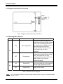
2.2 Diagram of Internal Pin J5 and J6
Fig 2
Diagram of Inner Structure of J5 and J6
2.3 Switching Mode Options
Switch
Status
Function
ON
Non-retriggerable
OFF
Retriggerable
ON
Enable LDR
OFF
Disable LDR
K1
K2
Note
This module cannot be triggered
continuously during the output of high
level. It can only be triggered when
the module starts outputting low level
after resuming from high level.
Interval between two high levels is
2-3s. Refer to fig 4 for time
sequence.
This module can be triggered
continuously during the output of high
level. The module will not stop
outputting high level until there is no
trigger. Refer to fig 3 for time
sequence diagram.
When ambient light reaches a certain
level, the module will not be triggered
and will keep outputting low level.
Ambient light is irrelevant to the
trigger of the module.
Table 2 Switch Status Diagram
Note:
+V CC should be used to connect power supply when a relay is connected like
shown in fig 2.
© 2004-2009 Sure Electronics Inc.
DC-SS502_Ver1.0_Page 3