1
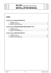
AU-201 Authentication Unit (IC Card Type)
INSTALLATION MANUAL
Applied Machines: C650/C550/C451/C353/C253/C203
COLOR MFP (Color/B&W): 50 ppm/65 ppm, 45 ppm/55 ppm, 45 ppm/45 ppm, 35 ppm/35 ppm, 25 ppm/25 ppm,
20 ppm/20 ppm
Product Code: A00H/A00J/A00K/A02E
I. Accessory parts
No.
Name
Shape
Q’ty
1. Authentication
unit
After unpacking, be sure to get rid of the
packaging materials and keep them out of
the reach of children.
1
Putting the head in the plastic bag
involves danger of suffocation.
A09NIXC003DB
2. Ferrite core
Note:
• The working table and the local interface kit
need to be mounted before to install this unit.
• Take the same procedures, though the machine
illustrations or adjustment screens are different
from the ones in the procedures.
1
A09NIXC008DA
3. Velcro fastening A
(hook)
(25.4 × 10 mm)
3
4. Velcro fastening B
(loop)
(25.4 × 10 mm)
3
5. CD-ROM
1
4040IXC111DA
6. Safety
information
guide
1
7. Quick guide
1
8. Installation
manual
1
set
4980IXC019DA
E-1
A09N-9550-01
II. Installation procedures
4. Fix the authentication unit on the working table
using velcro fastenings (A and B) furnished with
the unit.
A: three places on the back of the authentication
unit
B: three places on the working table
1. Turn off the machine and unplug the power cord
from the power outlet.
2. Attach the ferrite core as shown in the illustration.
Note:
• Install the ferrite core by winding the cable two
turns.
• Place the ferrite core approximately 60 mm
away from the authentication unit.
A09NIXC004DB
5. Attach the cord clamp onto the position shown in
the illustration.
Note:
The cord clamp is furnished with the working table
(WT-502).
A09NIXC009DA
A09NIXC010DA
3. Remove the cap from the working table (one
place).
A09MIXC008DA
6. Run the authentication unit cable through the
hole in the working table.
7. Route the cable as shown in the illustration so
that the wire saddles (three places) and the cable
clip (one place) hold the cable securely.
A09MIXC003DA
A09NIXC006DA
E-2
III. Setting IC cord authentication
<When installing to C650/C550/C451>
8. Remove the right rear cover.
1. Plug the power cord into the power outlet and
turn on the machine.
2. Display the Service Mode screen.
(For details of how to display the Service Mode
screen, see the service manual.)
3. Display the Billing Setting screen.
(To display the Billing Setting screen, press Stop
→ 9 on the Control Panel.)
4. Touch “Management Function Choice.”
A00JIXC071DA
9. Connect the cable from the authentication unit to
the machine.
A09MIXE012DA
5. Touch “Authentication Device2.”
6. Touch “Card.”
A09NIXC007DA
10. Reinstall the right rear cover that has been
removed in step 8.
<When installing to C353/C253/C203>
8. Connect the cable from the authentication unit to
the machine.
A09NIXE011DB
7. Touch “END.”
8. Touch “Exit” on the Service Mode screen.
9. Turn OFF and ON the Main Power Switch.
Note:
When displayed the Service Mode screen, be sure
to turn off the main power after exiting the Service
Mode screen and wait for 10 seconds or more
before turning on.
A09NIXC012DA
E-3