1
PK-517 Punch Kit
INSTALLATION MANUAL
Applied Machine: FS-527
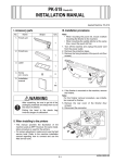
I. Accessory parts
No.
Name
II. Installation procedures
Shape
Note:
When mounting the punch kit, mount it before
mounting the finisher to the machine.
Q’ty
1. Punch unit
1. Turn off the machine and unplug the power cord
from the power outlet.
2. Remove the protective tape.
1
A10EIXC001DA
2. Punch box
1
A10EIXC002DA
3. Label
1
4512IXC053DA
A10EIXC003DA
4. Installation
manual
3. If the finisher is mounted on the machine, remove
the finisher.
Note:
For the finisher removal procedure, see installation manual for finisher.
1
set
4980IXC019DA
4. Remove the exit tray from the finisher.
After unpacking, be sure to get rid of the
packaging materials and keep them out of
the reach of children.
Putting the head in the plastic bag
involves danger of suffocation.
Note:
This manual provides the illustrations of the accessory parts and machine that may be slightly different
in shape from yours. In that case, instead of the
illustrations, use the appearance of your machine to
follow the installation procedure. This does not
cause any significant change or problem with the
procedure.
Y111590-5
A10EIXC004DA
E-1
Installation Manual
5. Remove the upper cover from the finisher (four
screws).
8. Open the cover of the finisher as shown in the
illustration and place the punch kit on the finisher.
A10EIXC005DB
6. Remove the plate from the finisher as shown in
the illustration (two screws).
A10EIXC008DA
9. Connect the punch kit connector to the finisher.
A10EIXC006DA
A10EIXC009DA
7. Remove the plate from the finisher as shown in
the illustration (three screws).
A10EIXC007DA
Installation Manual
E-2
Y111590-5
12. Align the middle mark on the punch kit with the
dowel on the plate and secure the punch kit (two
screws).
Note:
Use the screws removed in step 6.
10. Slightly raise the punch kit and insert the plate
removed in step 7 between the finisher and the
punch kit.
Note:
Align the three dowels on the finisher with the
three dowel holes on the plate.
A10EIXC012DA
13. Attach the upper cover removed in step 5 to the
finisher (four screws).
14. Attach the exit tray removed in step 4 to the finisher.
15. Install the furnished punch box.
Dowel
A10EIXC010DB
11. Secure the plate to the finisher with the three
screws removed in step 7.
A10EIXC013DA
16. Affix the furnished label to the front door of the
finisher as shown in the illustration.
A10EIXC011DA
A10EIXC014DA
17. Mount the finisher to the machine.
Note:
For the finisher mounting procedures, see installation manual for finisher.
Y111590-5
E-3
Installation Manual
III. Punch option setting
4. Loosen the two screws that hold the punch unit in
place.
1. Plug the power cord into the power outlet and
turn on the machine.
2. Display the Service Mode screen. (For details of
how to display the Service Mode screen, see the
service manual.)
3. Touch “Finisher.”
4. Touch “Punch option setting.”
5. Touch “PK-517” and select a desired number of
holes.
6. Touch “decision.”
7. Touch “END.”
8. Touch “Exit” on the Service Mode screen.
Screw
A10EIXC015DA
IV. Punch hole deviance adjustment
5. Move the punch unit back and forth to adjust its
position, referring to the guide lines.
1. Make a copy in the punch mode.
(Refer to the user’s guide (copy operations))
2. Fold the copy into halves and check for possible
deviation in the punch hole positions.
Specifications: 0 ± 2.0 mm
A10EIXC016DA
6. After the adjustment, tighten the two screws loosened in step 4.
7. Close the upper cover of the finisher.
8. Make a copy and check the punch hole positions
again.
A10EIXC018DA
* If the positional deviation of the punch holes is
not within the accepted range, take the following
steps.
3. Open the upper cover of the finisher.
A10EIXC019DA
Installation Manual
E-4
Y111590-5
V. Punch hole position adjustment
VI. Punch regist loop size adjustment
1. Make a copy in the punch mode.
(Refer to the user’s guide (copy operations))
2. Measure width A on the copy and check to see if
the measured dimension falls within the specified
range.
<North America: 2 holes, 3 holes>
Specifications: 9.5 ± 1.0 mm
<Europe: 4 holes>
Specifications: 11 ± 1.0 mm
<Sweden: 4 holes>
Specifications: 10.5 ± 1.0 mm
• If the measured width A outside the specified
range, perform the following procedure to punch
hole position adjustment.
1. Make a copy in the punch mode.
(Refer to the user’s guide (copy operations))
2. Check the tilt of the output paper.
• If it tilts, follow the procedures below for punch
loop adjustment.
<North America:
2 holes>
A
3. Display the Service Mode screen.
(For details of how to display the Service Mode
screen, see the service manual.)
4. Touch “Finisher.”
5. Touch “FS-FN adjustment.”
6. Touch “Punch Regist Loop Size.”
7. Set the correction value using the
/
keys.
• To make loop length larger, enter a positive value.
• To make loop length smaller, enter a negative
value.
8. Touch “END.”
9. Touch “OK.”
10. Touch “Exit” on the Service Mode screen.
11. Make a copy again and check the deviance of
punch hole position.
<North America:
3 holes>
A
4512IXC056DA
<Europe: 4 holes>
A
4512IXE057DA
<Sweden: 4 holes>
A
4512IXE061DA
4512IXE062DA
3. Display the Service Mode screen.
(For details of how to display the Service Mode
screen, see the service manual.)
4. Touch “Finisher.”
5. Touch “FS-FN adjustment.”
6. Touch “Punch Horizontal Position.”
7. Set the correction value using the
/
keys.
• To make width A wider, enter a positive value.
• To make width A narrower, enter a negative
value.
8. Touch “END.”
9. Touch “OK.”
10. Touch “Exit” on the Service Mode screen.
11. Make a copy and check the punch hole positions
again.
Y111590-5
E-5
Installation Manual