1
Amptek Inc.
User’s Manual for PC4 Interface Boards Rev A4
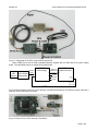
Figure 3. Photograph of the PC4-3 with the DP4 and XR100.
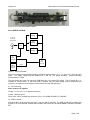
Many OEMs use the PA-210/230 preamplifier/detector together with the DP4 and PC4-3 power supply
board. This total OEM solution is configured as shown below.
Amptek
AXR
Detector
Amptek
PA-210/230J1
Preamplifier
PC4-3
Power Supply
Signal &
Power
flex cable
Power &
USB/RS-232
J1
J4A
J3
OUT
J5
flex cable
+5VDC
RS232
DP4
Digital Processor
JP6
INPUT
JP7
USB
Signal to pin 1
Shield to pin 2
Signal
coax cable
Figure 4. Block diagram of the PC4-3, DP4, detector, and PA210/230 preamp. The detector must be used with a
heat-sink like the right angle one shown.
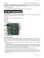
Figure 5. Photo of PC4-3, DP4, Detector, PA210/230.
Page 2 of 8