1
Amptek Inc.
User’s Manual for PC4 Interface Boards Rev A4
The RC filter has a series resistance of 30 MΩ. This provides some current limiting, but it also means that the
bias cannot be accurately measured at this node with a conventional DVM. Most DVMs have an input
impedance of approximately 10 MΩ, so will only measure a fraction of the actual voltage.
Thermoelectric Cooler Discussion
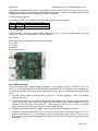
The control circuit for the thermoelectric cooler is shown in the schematic below. This circuit maintains a fixed
temperature rather than a fixed output voltage. A temperature sensor is located in the detector hybrid. The
conditioning circuitry generates an output of 10 mV/K. This is compared to the set point to generate the error
signal.
Supply
TEC
Power
RC Filter
Temperature
Sensor
Conditioning
3.3
V
TP1
R9
VR2
10K
Error
Amplifier
TP8
R31
R30
15K
Figure 11. Schematic for thermoelectric cooler supply circuit. The board is shipped with R9 and R31 not
installed, so VR2 adjusts the set point. TP8 measures the set point while TP1 measures the actual temperature.
Both are in units of 10 mV/K, i.e. a 250 K temperature yields 2.5 V.
There exists a maximum temperature differential which a given cooler can achieve. If the set point is lower than
this, then the supply will provide maximal cooling (with an output current limit) but the detector temperature is no
longer regulated. It will change as the system temperature changes. A two stage cooler can typically reach a
temperature of about 220 K under normal, laboratory conditions.
Amptek detectors use a diode temperature sensor that must be calibrated. This has been done at the factory,
but if the calibration is lost the procedure is:
1. Locate TMPSET and read the voltage with a multimeter.
2. Adjust VR2 until the voltage reaches its maximum voltage of approximately 3.25 volts.
3. Disconnect the multimeter.
4. Connect a detector to the PC4-3. The detector will now be at room temperature.
5. Locate TMON and read the voltage with a multimeter.
6. Adjust VR1 until the voltage on TMON matches room temperature (i.e. 293 K = 2.93 V).
7. Disconnect the multimeter.
8. Locate TMPSET and connect the multimeter.
9. Adjust VR2 until the voltage reaches your required temperature set point. See above for 1 and 2-stage
cooler temperature ranges.
10. Disconnect multimeter.
11. Diode calibration is now complete.
Page 6 of 8