1
Amptek Inc.
User’s Manual for PC4 Interface Boards Rev A4
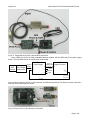
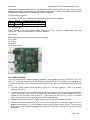
Figure 6. PC4-3 and DP4 stacked together.
PC4-2 SPECIFICATIONS
+3.3V
Supply
Power In
2.5 to 5.5V
Center GND
Auto
Switch
+5V
Supply
-5V
Supply
J2
USB
Connector
P1
RS232
Connector
9 pin D
JP2
DP4
Connector
RS232
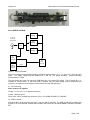
Figure 7. PC4-2 Schematic
The PC4-2 contains three separate switching regulators which produce +5 V, -5 V, and +3.3 V from the input
power. The supply voltage must be between 2.5 V and 5.5 V for proper operation. Nominal switching
frequencies are >1 MHz.
The input power can come from either the USB power pin or an external DC supply. The DC power plug, J1,
contains an internal switch. If the power jack is inserted, then the power supply current comes from this
connector, otherwise the power supply current is drawn from the USB power pin.
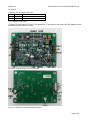
J1: DC Power Plug
Note: center pin is negative.
Voltage: 2.5 V to 5.5 V (6 V absolute maximum)
Current: 500 mW typical
Power Jack: 2.5mm, example part numbers: CUI Inc. PJ-102BH, DIGI-KEY CP-102B-ND
J2: USB Connector
Standard USB Type B connector receptacle. Only D+ and D- are used. The USB ground may be tied to DP4
ground via J2 or left isolated. Example part numbers: MILL-MAX: 897-30-004-90-000000, DIGI-KEY: ED90003ND.
Page 3 of 8