1
1 DOOR ACCESS CONTROLLER WITH FINGERPRINT
STAR FINGER007
USER’S MANUAL
Access Controller
Rev. V1.0
20030516
User’s Manual
STAR FINGER007
Table of Contents
1. IMPORTANT SAFETY INSTRUCTIONS
2. INTRODUCTION
Page 4
Page 6
2.1 IDENTIFYING SUPPLIED PARTS
2.2 ABOUT STAR FINGER007
2.3 SPECIFICATION
3. PRODUCT OVERVIEW
Page 8
3.1 FUNCTIONS
3.2 PRODUCT EXPLANATION
3.2.1 Panel Description
3.2.2 Color Coded & Wiring Table
4. INSTALLATION REQUIREMENTS
Page 12
4.1 WIRE/CABLE
5. INSTALLATION
Page 13
5.1 TEMPLATE (Wall Mount)
5.2 BACKUP BATTERY S/W
5.4 SYSTEM INITIALIZATION (Extra Reader Port)
5.4 WIRING
5.4.1 POWER
5.4.2 INPUT CONNECTIONS
5.4.3 OUTPUT CONNECTIONS
5.4.4 READER CONNECTIONS (Extra Reader)
6. COMMUNICATIONS
Page 17
6.1 RS232 COMMUNICATION PORT CONNECTION
6.2 RS-422 COMMUNICATION PORT CONNECTION
6.2.1 RS-422 COMMUNICATION (STANDALONE)
6.2.2 RS-422 COMMNUNICATION
(MULTIPLE FINGER007 CONNECTIONS)
6.3 DIAL UP MODEM
6.4 TCP/IP CONVERTER (EXTERNAL VERSION)
7.
BASIC SETTINGS
Page 20
7.1 INITIALIZATION OF FINGER007
7.2 HOW TO ENTER THE SETUP MENU
7.3 DATE AND TIME SETTING
7.4 ID REGISTRATION
8. OPERATION
Page 25
8.1 NORMAL OPERATION
8.2 DEFAULT SETTING
2
20030516
User’s Manual
9.
SETTING CHANGES
STAR FINGER007
Page 26
9.1 SETUP MENU F1
9.2 SETUP MENU F2
9.3 SETUP MENU F3
9.4 SETUP MENU F4
APPENDIX
Page 50
A. THE RELATION BETWEEN INPUT AND OUTPUT (DEFAULT)
B. TROUBLE SHOOTING
WARRANTY AND SERVICE
Page 56
TEMPLATE
Page 57
3
20030516
User’s Manual
1. IMPORTANT SAFETY INSTRUCTIONS
STAR FINGER007
To prevent injuries to persons and damages to property, please read all the instructions and follow
them whenever you deal with this product.
After reading, please put this instruction manual where it can be easily seen for the system operator.
ON INSTALLATION AND POWER
Use 12V DC power ONLY.
- Connecting to higher than 12V DC may result in a risk of electric shock, fire, or heavy damage of the unit.
Do NOT install this product at places with wet or metallic dust, or that can be watered.
- There may be risks of electric shock and fire.
Do NOT install this product near electric motors running.
- The unit may not operate normally.
Do NOT set this product near heaters or any thing that produces heat.
- There may be a risk of fire.
Be ALWAYS careful not to short-circuit any part of the circuitry with tools like a screwdriver in hand.
- There may be a risk of fire or heavy damage of the unit.
ON MAINTENANCE
Do NOT use any kind of liquid for cleaning.
- There may be a risk of electric shock, fire or heavy damage of the unit. Use an air spray, if needed.
Users are cautioned NOT to attempt repair of this product or modify the wirings set by the installer at their
own discretion.
- It may pose the risk of fire, hardware damages, or abnormal operations of the unit.
It is recommended not to use a flammable spray or something easy to burn near this product.
- There may be the risk of an explosion or fire.
Keep the unit away from any unauthorized people.
- It may cause abnormal operations of the unit.
4
20030516
User’s Manual
NOTICE
STAR FINGER007
Please, contact a designated service center or the outlet at which the product was purchased when
A. Any liquid has been spilt or sprayed onto the product. In this case, cut the power off first.
B. The product seems to be operating abnormally.
C. The unit exhibits a distinct change in performance.
D. The unit has fallen to be broken down or damaged on its case.
* The cost of repairing can be charged for troubles due to the improper handling or negligence of users or the
operator.
5
20030516
User’s Manual
2. INTRODUCTION
STAR FINGER007
2.1 IDENTIFYING SUPPLIED PARTS
Please unpack and check the contents of the box. (Optional accessories, if purchased, may be included in
the package)
2.2 ABOUT STAR FINGER007
The STAR FINGER007 is a highly advanced, intelligent single door controller with a powerful 32bit and
dual 8bit microprocessor to meet the market requirement for a robust integrated solution for access
control and time & attendance. The unit is designed to be flexible and reliable as well as provide the
ultimate in biometric high security at a reasonable cost. This user-friendly device allows you to register
up to 720 fingerprint IDs (optional 2,000/4,500); add / delete user IDs conveniently; store up to 26,000
transactions in its event buffer; easily report and archive information to Excel or Access databases; and
ultimately successfully manage all access control and time & attendance issues. With a built-in 4" RF
reader, keypad for Personal Identification Numbers (PIN), and a sophisticated biometric fingerprint
analyzer, the FINGER007 offers up to three levels of ID verification. Any combination of prox, PIN, and
biometric may be used and different verification levels can be custom programmed for each user or user
group. Four independent input ports can be utilized for a wide variety of controls including exit buttons,
door contacts, PIR sensors and fire detection equipment. Actions to be taken and time settings can be
programmed with the front keypad or via the intuitive Windows based software program. The
FINGER007 can be used both as a stand-alone system and also be networked. All control setting values
such as ID numbers, inputs/outputs, real-time clock, time schedules, and event transaction reports can
be uploaded and/or downloaded to and from the host computer. The compact and contemporary unit is
easily installed and programming requires no significant knowledge of access control or time &
attendance. The Three-LED indicator lights inform you of the systems operating status at real time and
the digital display acts as a programming aid as well as a regulation time clock. By bundling the ultimate
in high security access control and comprehensive employee management tools into a compact user
friendly unit, the field proven STAR FINGER007 has made real what until recently was thought only to
be possible in science fiction.
6
20030516
User’s Manual
2.3 SPECIFICATION
CPU
Memory
Power
Card Holders/
Event Buffer
Reader Port
Reader Data Format
Communication port
STAR FINGER007
32bit, dual 8bit Microprocessor
Program Memory : 64KB EEPROM
Data Memory : 512KB SRAM(battery backup)
DC 12V/ 350mA max.(excluding lock current)
Card Holders : 720(optional 2,000/4,500)
Event Buffer : 26,000
1 Extra port, 1 Internal port
Standard 26bit Wiegand(STAR FINGER007)
Standard 34bit Wiegand(STAR FINGER007SR)
8 bit burst Format for keypad reader
RS232/RS422(up to 32 channels) selectable 4800,
9600(Default), 19200, 38400bps communication speed
Input/Output
4 Input ports/ DC12V/ 20mA
2 Relay Output ports/ DC12V/ FORM-C Relay 2A max.
2 TTL Output ports: DC5V/ 20mA
Keypad
LCD
Light source
Mounting
Color
Material
Self diagnostic
Reset
Operation Status
Operation Environment
Weight
Dimensions
Certification
16 Keypad (Back lighting)
1 x LCD module, 2Lines x 16ch, 65.6 x 13.8mm view area
LED (finger unit)
Wall mounted
Dark pearl gray
Polycarbonate
Yes
Power on Reset and Watchdog timer reset
3 LED (red, green, yellow) in dicators
0°C ~ +40°C, 10% ~ 90%(Humidity)
525g
161.6mm x 122.6mm x 36.5mm
FCC Class A part 15, UL294, MIC
7
20030516
User’s Manual
3. PRODUCT OVERVIEW
STAR FINGER007
3.1 FUNCTIONS
Stand-Alone Operation
The STAR FINGER007(STAR FINGER007SR) is capable of having two readers(entry and exit). The
unit receives card data signals from the RF readers and determines whether or not to unlock the door.
When an input signal is sent, for example from and activated sensor or if the exit button pressed, the
controller generates and logs an appropriate response. All events are kept in its own memory and sent
to the host computer. The access controller is a true standalone device that in the event of a
malfunction, will not affect other units, even if used in conjunction with one another.
Operation with Host Computer
All event transactions can be managed via the host computer. The data transmitted from the controller
can be displayed and stored on the host PC.
Data Backup
The controller retains all user information and event data for 30 days, even in the event of power failure.
CAUTION : Battery S/W must be set correctly before the unit running.
(See the INSTALLATION section)
Keypad
If the STAR FINGER007 is not connected to host PC, the integrated keypad and LCD display module
can also be used for the entire programming process manually.
Anti-Pass-Back
Using an additional proximity reader foe exiting, the Anti-Pass-Back mode can be set. Anti-Pass-Back
mode prevents any entry or exit when the registered user did not properly followed one entry and one
exit by the Anti-Pass-Back rule. APB only allowed exit for the user once got into the door first and it
doesn’t allow any user trying twice entry or twice exit
Input/Output
built-in 4 inputs and 4 outputs (2 relay outputs and 2 TTL outputs) which can
be used to manipulate a wide variety of controls.
The STAR FINGER007 has
Time Schedule Setup
You can program 10 time schedules and apply one time schedule to each user. Each time schedule has
8 different time zones from Monday to Sunday(7 time zones) and one holiday. Each time zone has 5
different time codes so you can program 5 different time codes to each day. Also you can program time
schedule for individual inputs and outputs. Note that the time schedule for input is activated time code
for input device so that the input is activated during the time code on this time schedule. Each time
schedule is linked to one of holiday schedule and this linked holiday only validates to holiday time code
8
20030516
User’s Manual
of the time schedule.
STAR FINGER007
Holiday Schedule Setup
Excepting Sunday, you can program 32 holidays to one holiday schedule. Each holiday schedule is
linked to one time schedule which has time code for holidays. So you can program all holidays to
holiday schedule and the time code for holidays is programmed to holiday time zone of time schedule.
Example : A : Holiday schedule 01 linked to time schedule 01,
Holiday schedule 02 linked to time schedule 02.
B : Holiday schedule 02 linked to time schedule 01,
Holiday schedule 01 linked to time schedule 02.
Forced Door Open and Door Open Alarm
When door is opened by force, Door Contact Output is generated. And, when the door is being opened
by normal operation, after 20 sec. door-open alarm(blink buzzer) will be generated until the door is
closed.
Duress Alarm
You can select Duress Mode enable or disable. If you select Duress Mode enable, in case of Duress,
enter the 2 digit Duress Password and press <ENT> and open the door using general process. If you
registered ID, then Duress Output will be generated, and alarm event will be sent to the host PC.
1:N Certification (IDENTIFICATION)
You can certify using the fingerprint alone without RF card or PIN. You can set this function through the
<TYPE SELECTION> in SETUP MENU F1. In the IDENTIFICATION MODE, the security level gets
higher automatically, FRR(False Rejection Ratio) as well, but FAR(False Accept Ratio) gets lower,
which may result in a lower recognition ratio.
When using this mode, you have to press the <ENT> key first, then the fingerprint scanner waits for a
fingerprint to be scanned. When a fingerprint-scanning is completed, FINGER007 compares the data
and makes corresponding outputs.
* CAUTION : The number of registrants must be 50 or less.
9
20030516
User’s Manual
STAR FINGER007
3.2 Product Explanation
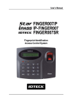
3.2.1 Panel Description
LCD
3 LED (showing
system status)
Fingerprint
Input window
16 Numeric keypad
Function Key
OFF state
ON state
BAT connection S/W
•
FINGER007(of V4.70 or higher) has a S/W(reverse side – Template hole) for the backup battery
connection. Before the FINGER007 installation, it needs to be connected before H/W initialize so
that backup battery can retain the memory during power failure.
10
20030516
User’s Manual
STAR FINGER007
3.2.2 Color Coded & Wiring Table
IO PORT NAME
POWER
Main Power(+12V)
Power Ground
OUTPUT
Door Relay(COM)
Door Relay(NC)
Door Relay(NO)
Alarm Relay(COM)
Alarm Relay(NC)
Alarm Relay(NO)
TTL Output1
TTL Output2
INPUT
Exit Button
Door Sensor
Aux Input 1
Aux Input 2
EXTRA READER
Wiegand Data0
Wiegand Data1
RS232 INTERFACE
RS232-TX
RS232-RX
RS422 INTERFACE
RS422-TX(-)
RS422-TX(+)
RS422-RX(-)
RS422-RX(+)
SIGNAL NAME
COLOR CODED
+12V
GND
RED
BLACK
COM(1)
NC(1)
NO(1)
COM(2)
NC(2)
NO(2)
TTL1
TTL2
Gray with Red stripe
Blue with White stripe
White with Red stripe
White
Purple with White stripe
Purple
Orange with White stripe
Brown with White stripe
EXIT
CONTACT
IN1
IN2
Orange
Yellow with Red stripe
Green
Green with White stripe
DATA0
DATA1
Pink
Cyan
TXD
RXD
Black with White stripe
Red with White stripe
TX(-)
TX(+)
RX(-)
RX(+)
Yellow
Gray
Blue
Brown
11
20030516
User’s Manual
4. INSTALLATION REQUIREMENTS
STAR FINGER007
Installing the FINGER007 is a relatively easy task. It can be installed with common hand tools and readily available
communications wire. This section provides information about wiring, wire runs and other information to make the
installation quick and easy.
4.1 WIRE/CABLE
Good electrical connections will minimize the line losses and avoid damages to the FINGER007 control electronics.
Use good quality and proper thickness of wire with durable insulation such as vinyl or PVC. It may be faster and
much economical to run multiple, twisted pair cable rather than individual pairs. The following cable and wire
thickness from the Belden Master Catalog 885 are adequate for the most FINGER007 applications. These are
offered as a reference only.
Belden No. 9745 3 twisted pairs, 22 AWG, 7/30 stranded, unshielded, PVC insulation and jacket,
14.7 ohms/1000 feet (about 300meter).
Belden No. 9750 3 twisted pairs, 20 AWG, 10/30 stranded, unshielded, PVC insulation and jacket,
10.3 ohms/1000 feet (about 300meter).
Belden No. 8303 3 twisted pairs, 22 AWG, 7/30 stranded, shielded, overall foil/braid shield, PVC insulation and
jacket, 14.7 ohms/1000 feet (about 300meter).
CONDUIT
The FINGER007 does not normally require conduit. However, some location may require conduit for wire
protection. Check installation requirements and specifications for your site.
COMMUNICATIONS WIRING
FINGER007 communication is required for using twisted pair wires.
RS232C : 15 meters
RS422 : 1200 meters
POWER WIRING
Wires supplying power to FINGER007 may be either twisted or non-twisted pairs. Select the proper wire size to
minimize line losses.
OTHER WIRING
Other wiring not mentioned above may be twisted or non-twisted pair wires. This would include wires to door
contact sensors, door lock devices and other auxiliary devices. Wire runs should dictate the wire size used.
CAUTION : Install a surge absorber or reverse surge protector(diode) at any relay contact that switches DC
voltages to an inductive load.
EARTH GROUND
The FINGER007 must be properly grounded to the earth for safety reasons and to prevent damage to
the micro-electronics due to electrostatic discharges. The FINGER007 must be connected to earth
ground either through conduit, if used, or through a separate ground wire.
On-site connection to earth ground can be accomplished through:
A earth ground rod, A metal water pipe, The building’s structural steel, A ground grid
12
20030516
User’s Manual
5. INSTALLATION
STAR FINGER007
5.1 TEMPLATE
• Tear off last page and use provided template to drill two 6-32 holes and one ½” hole on the proper location
of the wall to mount the Wall Mount bracket as shown below.
(If the gang box is already installed on the wall then skip this step.)
• Using 2 screws, install wall mount to the wall.
* CAUTIONS *
Before mounting the STAR FINGER007 unit to the Wall Mount bracket, an operational test of the unit
should be completed, because the locking pins will lock the unit to the Wall Mount. Removing the unit from
the Wall Mount bracket after it has been snapped in place may cause damage to the bracket and prevent
reattachment.
• Insert 5 O-Rings to the Wall Mount as indicated, then run the cable from the main unit through the center
hole and snap in place the main unit to Wall Mount. Make sure that the main unit is securely locked in place
with Wall Mount.
13
20030516
User’s Manual
STAR FINGER007
5.2 BACKUP BATTERY S/W
FINGER007(of V4.70 or higher) has a S/W(reverse side – Template hole) for the backup battery
connection, which is left open circuit to prevent any current consumption of backup battery(Figure : S/W
setting). Before the FINGER007 installation, it needs to be connected so that backup battery can retain the
memory during power failure.
Figure : S/W SETTING
Figure : S/W location
5.3 SYSTEM INITIALIZATION (Extra Reader Port)
You must operate H/W initialization, before the FINGER007 installation.
Of V4.70 or higher, you must connect battery backup S/W in reverse side before H/W initialization.
You can H/W initialize using extra reader port. First, turn off the system power and connect 3 wires (pink,
cyan and black(GND)), and turn on the system power. Then you can hear “Initialize beep” and display
picture.
System Initialize
Master Password
1 – Yes, 0 - No
[____]
Errore.
System
System is Clear
Initializing...
Remove Wires!!
Errore.
1.
2.
3.
4.
Errore.
Errore.
: If you want H/W initializing, enter key <1>.
: Enter initial master password(<3141>).
: Showing initializing.
: After initializing – Main power OFF and separate 3 wire and main power ON again.
5.4 WIRING
5.4.1 POWER
14
20030516
User’s Manual
- Connect (+) wire of DC 12V power to +12V(Red wire) terminal.
- Connect GND(-) wire of DC 12V power to GND(Black wire) terminal.
STAR FINGER007
5.4.2 INPUT CONNECTIONS
Exit Button Connection (EXIT)
- Connect one wire from an Exit Button to EXIT(Orange wire).
- Connect the other wire from the Exit Button to the GND(Black wire).
Door Contact Sensor Connection (CONTACT)
- Connect one wire from a Door Contact Sensor to CONTACT(Yellow with Red stripe).
- Connect the other wire from the Door Contact Sensor to GND(Black wire).
Auxiliary Input Connection (Applied IN1, IN2)
- Connect one wire from an Auxiliary Input Device to one of the IN1(Green wire), IN2(Green with White
stripe).
- Connect the other wire from the Auxiliary Input Device to GND(Black wire).
Figure : INPUT DEVICES CONNECTION
5.4.3 OUTPUT CONNECTIONS
Door Lock (Power Fail Safe) Connection (Relay 1)
- Connect COM port of Relay 1 to + 12V.
- Connect NC port of Relay 1 to (+)wire of door lock device.
- Connect GND port to (-)wire of door lock devices.
Door Lock (Power Fail Secure) Connection (Relay 1)
- Connect COM port of Relay 1 to + 12V.
- Connect NO port of Relay 1 to (+)wire of door lock device
- Connect GND port to (-)wire of door lock devices
Alarm Device Connection (Relay 2)
- Connect COM port of Relay 2 to + 12V.
15
20030516
User’s Manual
- Connect NO port of Relay 2 to (+)wire of Alarm devices.
- Connect GND port to (-)wire of Alarm devices
STAR FINGER007
Figure : DOOR LOCK, ALARM DEVICE CONNECTIOIN
CAUTION : Please add one DIODE as shown above.
DIODE : Fast recovery DIODE(current : Min. 1A), 1N4001 ~ 1N4007 or similar
5.4.4 READER CONNECTIONS(Extra Reader)
Proximity Reader Connection
- Connect (+)wire of the Proximity Reader to +12V(Red wire)
- Connect (-)wire of the Proximity Reader to GND(Black wire)
- Connect Data-0 wire of the Proximity Reader to DATA0(Pink wire)
- Connect DATA-1 wire of the Proximity Reader to DATA1(Cyan wire)
• Compatible Readers(Extra Reader) :
FINGER007/iPFINGER007: Standard 26bit Wiegand Format Proximity Readers
Standard 26bit Wiegand + 8bit Burst Format Proximity and keypad Reader
FINGER007SR : Standard 34bit Wiegand Format Proximity Reader
Standard 34bit Wiegand + 8bit Burst Format Proximity and keypad Reader
• Recommended Readers :
FINGER007 : RF-TINY, RF10/20/30/70/500, RFK101, FGR006, FGR006EX
iPFINGER007: iP10/20/30, iPK101
FINGER007SR : SR10/20/30, SRK101, FGR006SRB
16
20030516
User’s Manual
STAR FINGER007
Figure : READER CONNECTION
6. COMMUNICATIONS
6.1 RS232 COMMUNICATION PORT CONNECTION
A 9-pin connector (Serial communication connector, female) is required to connect the FINGER007 to a
host computer via RS232 communication Please follow the instructions.
- Connect RS232-TX port of FINGER007 to the pin 2 of the 9-pin connector.
- Connect RS232-RX port of FINGER007 to the pin 3 of the 9-pin connector.
- Connect RS232-GND of Finger007 to the pin 5 of the 9-pin connector.
- Plug in the 9-pin connector to COM1 or COM2 Port of the host PC.
- Install and run FINGER007 Application Software.
6.2 RS-422 COMMUNICATION PORT CONNECTION
6.2.1 RS-422 CONNECTION (STAND ALONE)
RS422/RS232 converter(CNP200) is required to use RS422 communication between the FINGER007
and a host computer. Please follow the instructions.
- Connect RS422-TX(+) of the FINGER007 to RS422-RX(+) port of the converter.
- Connect RS422-TX(-) of the FINGER007 to RS422-RX(-) port of the converter.
- Connect RS422-RX(+) of the FINGER007 to RS422-TX(+) port of the converter.
- Connect RS422-RX(-) of the FINGER007 to RS422-TX(-) port of the converter.
- Plug in the RS232 9pin connector of the converter to the COM1 or COM2 Port of the PC.
- Install and run FINGER007 Application Software.
17
20030516
User’s Manual
STAR FINGER007
Figure : RS-422 Communication between FINGER007 and Host Computer
6.2.2 RS-422 CONNECTION (MULTIPLE FINGER007 CONNECTIONS)
RS422/RS232 converter is required to use RS422 communication between multiple FINGER007s and
a host computer. Please follow the following instructions.
First, you have to connect all RS422 port of all FINGER007s in parallel.
- Connect RS422-TX(+) of one FINGER007 to RS422-TX(+) of another FINGER007.
- Connect RS422-TX(-) of one FINGER007 to RS422-TX(-) of another FINGER007.
- Connect RS422-RX(+) of one FINGER007 to RS422-RX(+) of another FINGER007.
- Connect RS422-RX(-) of one FINGER007 to RS422-RX(-) of another FINGER007.
Second, you have to connect one of RS422 port of FINGER007 to RS422/RS232 converter.
- Connect RS422-TX(+) of the one FINGER007 to RX(+) port of the converter.
- Connect RS422-TX(-) of the one FINGER007 to RX(-) port of the converter.
- Connect RS422-RX(+) of the one FINGER007 to TX(+) port of the converter.
- Connect RS422-RX(-) of the one FINGER007 to TX(-) port of the converter.
- Plug in the RS232 9pin connector of the converter to the COM1 or COM2 port of the PC.
- Install and run FINGER007 Application Software.
18
20030516
User’s Manual
STAR FINGER007
Figure : RS-422 Communication between FINGER007s and Host Computer.
6.3 DIAL UP MODEM
Please, see the Software manual.
6.4 TCP/IP CONVERTER (EXTERNAL VERSION)
Please, see the Software manual.
19
20030516
User’s Manual
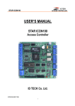
7.
STAR FINGER007
BASIC SETTINGS
If you turn on the system power
after connected 3 wires (pink, cyan
and black(GND)), you can enter
system initialize mode.
POWER ON
GENERAL BOOT
H/W RESET MODE
INITIAL BEEP( - - - -)
INITIALIZE BEEP( - - -)
In the system ready, LCD
display model name,
current date and time
NO
SYSTEM READY
SYS. INITIALIZE ?
YES
ID INPUT ?
WAIT INITIIAL MASTER P/W
("3141")
YES
YES
MASTER ID ?
RIGHT ?
NO
NO
NO
YES
ENTER SETUP MENU
DURESS P/W ?
NO
SETTINGIN SETUP MODE
END SETTING ?
NO
SYSTEM INITIALIZE
YES
DURESS FLAG
SET
RF_PIN_ENABLE SETTING
REGISTERED ID ?
WAITING REBOOT
YES
P/W, T/S, Door,
Finger, APB etc...
CHECK REGISTERED
ID'S FLAGS
NO
RIGHT ?
YES
OUTPUT CONTROL OF EACH
STATUS
NO
You can select output of each
status in "setup menu F2"
YES
20
20030516
User’s Manual
STAR FINGER007
7.1 INITIALIZATION OF FINGER007
Before system installation and when you can’t enter setup menu(system error or something wrong) then
you have to H/W initialize. You can H/W initialize using extra reader port. Turn off the system power and
connect 3 wires (pink, cyan and black(GND)), and turn on the system power. (Ref. 5.3 FINGER007
INITIALIZATION). Initializing will erase all stored data incl. registered IDs event data. Then you have to
setting system parameter.
Before first installation, you must H/W initialize.
In case of over V4.70, you must connect battery backup S/W in reverse side before H/W
initialization.
System Initialize
Master Password
System is Clear
1 – Yes, 0 - No
[3141]
Remove Wires!!
7.2 HOW TO ENTER THE SETUP MENU
To setup or to change the FINGER007 settings, you have to enter the SETUP MENU first. To do so, press
the 8 times <0> key for Master ID(Default setting “00000000”) and <ENT> key and press Master P/W
(Default setting “3141”) then you can get into SETUP MENU. There are 4 main SETUP MENU and you
first get into [SETUP MENU F1]. You can move to other SETUP MENU by pressing <F1> key for [SETUP
MENU F1], <F2> key for [SETUP MENU F2], <F3> key for [SETUP MENU F3] and <F4> key for [SETUP
MENU F4]. There are several SUB MENU in the main SETUP MENU and you can scroll up and down the
SUB MENU by pressing <4> and <6> key in the main SETUP MENU. If you press <ESC> key then
FINGER007 will exit the SETUP MENU then return to normal operation. You can also change the Master
ID in the [SETUP MENU F1].
The Master ID for FINGER007SR is 10 times <0> key (Default setting “0000000000” ), and default Master
P/W is <3141>.
7.3 DATE AND TIME SETTING
Select [TIME SETTING] in the [SETUP MENU F1] and enter the Year / Month / Date / Hour / Minute /
Second / Day(Total 15 digits) as shown below. LCD will display the new Date and Time after the time
setting completed but year and day will not be displayed. FINGER007 has 24 hours system and day
codes are 1 for Sunday, 2 for Monday, 3 for Tuesday, 4 for Wednesday, 5 for Thursday, 6 for Friday and
7 for Saturday. The Master ID for FINGER007SR is 10 digits number (Default setting “0000000000”).
21
20030516
User’s Manual
STAR FINGER007
Master card(PIN)/
Password/Fingerprint
FINGER_007 [F1]
MM/DD hh:mm:ss
Select ‘Time Setting’
menu
Initial Master key <00000000>)/
Initial password(<3141>)
Initial display
TIME SETTING
MM/DD hh:mm:ss
YYYYMMDDhhmmssW
200107050918305
ENT
<Year/Month/Day/Hour/Min./Sec./Day>
TIME SETTING
07/05 09:18:30
FINGER_007 [F1]
07/05 09:18:30
ESC
Initial display after time setting
: After change Master
: Initial Master
à Day code 1 : Sun., 2 : Mon., 3 : Tue., 4 : Wed., 5 : Thu., 6 : Fri., 7 : Sat.
For example, <200106071330253> for Tuesday, June 7, 2001 01:30:25PM.
7.4 ID REGISTRATION
You can register the User ID into FINGER007. Select [SETUP MENU F3] à [ID REGISTRATION] then
follow the steps below.
The Master ID for FINGER007SR is 10 digits number(Default setting “0000000000”).
Master Card(PIN)/
Password/Fingerprint
FINGER_007 [F1]
MM/DD hh:mm:ss
Initial display
ID REGISTRATION
Select ID Registration menu
(Setup menu F3)
Initial Master pin(<00000000>)/
Initial password(<3141>)
ENT
ID REGISTRATION
1 - Card, 2 - Key
22
20030516
User’s Manual
STAR FINGER007
1. Registration by RF Cards (FINGER007 only)
<1>Key
Put ID CARD
Scanning…
25500100
Approach card
reader1
PW1234 TS00 RD3 FPX
Input PW/TS/RD/FP
Not using Fingerprint (FP:0)
Using Fingerprint
(FP:1)
success
To Register FP
Put Your FP On..
Input fingerprint first time
False
success
Lift and Put FP
Waiting…
completion
Input fingerprint second time
Display false message, and return
False
Registration mode.
2. Registration by Keypad (FINGER007 & FINGER007P)
<2>Key
Input
Key InPut ID
à ¦ ________
00000100
Registration Key
PW1234 TS00 RD3 FPX
Input PW/TS/RD/FP
Not using fingerprint (FP:0)
Using fingerprint
(FP:1)
To Register FP
Put Your FP On..
Input fingerprint first time
False
Success
Lift and Put FP
Waiting…
Success
Completion
Input fingerprint second time
Display false message, and return
Registration mode.
False
3. After ID Registration complete, return initial display by enter <ESC> Key.
4. When register more than one ID, register first ID and continuously register other IDs.
5. If the ID number has a fingerprint already, in case of re-registration, the current fingerprint should be
scanned first.
6. You can’t register using RF card in FINGER007P.
23
20030516
User’s Manual
STAR FINGER007
• The [ID] is Personal Identification Number What you can use RF Card or Keypad. In case of RF Card,
ID number consists of 3-digits Facility code from 000 to 255 and 5-digits ID number form 00000 to
65535 so that the 8-digits ID number can not exceed 25565535. But, in case of Keypad, you can use 4
~ 8 digit for ID number. (ID number of FINGER007SR has 10-digits decimal numbers.)
• The [PW] is for password input the password is needed to access doors when the controller is
operating in RF+Finger(P/W) or RF+P/W+Finger mode. But regardless of the operating mode, it is
necessary to input a password when registering.
• The [TS] is Time Schedule code (00-10). [TS] is the Time Schedule for the Main Reader, Extra Reader.
When you present the card to Reader then the cardholder is only allowed the access of the door during
the Time Schedule code entered to TS__ . To control the accessible Time Schedule for each
cardholder, you must setup the Time schedules first and enter the Time Schedule code here. If you
want to access the door anytime for the cardholder then enter default Time Schedule code '00' for the
value.
• The [RD] is reader usage codes for the cardholder. If you put ‘1’ for RD then Main Reader is accessible
and if you put ‘0’ for RD then the cardholder can not access through the Main and Extra Reader, and
FINGER007 generates an error message “Access Door Error!” and displays on the LCD. To get access
through all Readers, you have to input “3” value for RD.
• The [FP] is for using fingerprint. If “1” is entered for the value, the user has to register fingerprint. And
the user certification of fingerprint in RF+Finger(P/W) and RF+P/W+Finger mode. If “0” is entered for
the value, fingerprint substitute by password.
24
20030516
User’s Manual
8. OPERATION
STAR FINGER007
8.1 NORMAL OPERATION
Power ON
When the Power is applied to FINGER007, the RED LED is turned on.
Registered Card Reading
When a registered card (or PIN) is read, the Door(Relay 1) will open for 3 seconds(Defaults) with the
Green LED on.
Exit Button
To request for exit from the inside, an Exit Button(or Extra Reader) can be used. The Door(Relay 1) will
open for 3 seconds(Defaults) with the GREEN LED on.
Alarms (unregistered/password/fingerprint/time schedule/door ERROR)
When an unregistered card is read, wrong password is input, wrong fingerprint is input, over the time
schedule, and access wrong door, the access is denied and the alarm(Relay 2) will be activated for 3
seconds(Defaults) with RED LED on.
8.2 DEFAULT SETTING
When you operate the FINGER007 first time or you initialize the FINGER007, the controller will setup
all values defaults (factory settings). You can change the settings for desired application.
Please refer to the APPENDIX for the default setting values.
25
20030516
User’s Manual
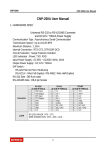
9.
STAR FINGER007
SETTING CHANGES
INITIAL DISPLAY
(MODEL NAME, CURRENT TIME)
NO
ID INPUT?
YES
MASTER ID /PW/
FINGERPRINT ?
YES
NO
OPERATE GENERAL
MODE
SETUP MODE
SETUP F1 MODE
1. MODE SELECTION
2. TIME SETTING
3. TYPE SELECTION
4. APB SETUP
5. COMM ID SETTING
6. DURESS MODE SET
7. BAUD RATE
8. EVENT CLEAR
9. MASTER ID CHANGE
10. SYS INITIALIZE
11. ID CLEAR
12. TIME SCHE CLEAR
13. RF_PIN_INPUT
SETUP F2 MODE
1. TIME SCHEDULE
2. HOLIDAY T/S
3. IN/OUT DEFINE
4. HOLIDAY INDEX
5. MODE INDEX
6. LCD DISPLAY
7. OUTPUT TIME
SETUP F3 MODE
SETUP F4 MODE
1. ID REGISTRATION
2. ID DELETE
3. ID LIST
4. ID COUNT
5. EVENT COUNT
1. F/W VERSION
2. SRAM TEST
3. OUTPUT TEST
4. LCD TEST
5. KEYPAD TEST
6. READER TEST
7. INPUT TEST
8. COMM TEST
9. GET GAIN IN FDA
10. SET GAIN IN FDA
. To setup or to change the FINGER007 settings, you have to enter the SETUP MENU first. To do so, input Master
ID(Default setting “00000000”), input Master P/W(Default setting “3141”) and input Master Fingerprint then you can get
into SETUP MENU. There are 4 main SETUP MENU and you first get into [SETUP MENU F1]. You can move to other
SETUP MENU by pressing <F1> key for [SETUP MENU F1], <F2> key for [SETUP MENU F2], <F3> key for [SETUP
MENU F3] and <F4> key for [SETUP MENU F4]. There are several SUB MENU in the main SETUP MENU and you can
scroll up and down the SUB MENU by pressing <4> and <6> key in the main SETUP MENU. If you press <ESC> key
then FINGER007 will exit the SETUP MENU and return to normal operation.
The Master ID for FINGER007SR is 10 times <0> key(Default setting).
26
20030516
User’s Manual
STAR FINGER007
9.1 SETUP MENU F1
MODE SELECTION
Seach Key <4>,<6>
RF Only (ID Only)
RF+FINGER(P/W) (ID+FINGER(P/W))
RF+P/W+FINGER (ID+P/W+FINGER)
TIME SETTING
Seach Key
TYPE SELECTION
Seach Key
STAND ALONE
USE/NOT USE
FINGER007P
USE/NOT USE
USE DUAL FINGER
USE/NOT USE
ADAPTIVE MODE
USE/NOT USE
IDENTIFICATION
USE/NOT USE
Seach Key
APB SETUP
NOT USE/USE/ALL CLEAR
Seach Key
Seach Key
27
20030516
User’s Manual
STAR FINGER007
Seach Key
DURESS MODE SET
USE/NOT USE
USE
Seach Key
BAUD RATE
DURESS P/W
4800/9600(DEFAULT)/19200
Seach Key
EVENT CLEAR
YES/NO
MASTER ID CHANGE
Seach Key
Seach Key
SYSTEM INITIALIZE
YES/NO
Seach Key
ID CLEAR
YES/NO
Seach Key
TIME SCHE CLEAR
YES/NO
Seach Key
RF_PIN_INPUT
ENABLE/
DISABLE
28
20030516
User’s Manual
9.1.4 ANTI-PASS-BACK MODE SETTING
APB SETUP
NOT USE
APB SETUP
--> NOT USE
APB SETUP
STAR FINGER007
. You can select whether the anti-pass-back(APB) mode is used or
not. To change mode, press <ENT> key.
(It only applies when the Door has Exit Reader)
. Press <4> or <6> to toggle the mode, from NOT USE to USE or the
reverse, and finish selecting by pressing <ENT> key.
NOT USE : Anti-pass-back mode is not applied.
USE
: Anti-pass-back mode is separately applied.
All Clear : Ignore all registered ID’s APB flag only once.
--> USE
APB SETUP
--> All Clear
9.1.5
COMMUNICATION ID(ADDRESS) DISPLAY
COMM ID SETTING
COMM ADDRESS
00
COMM ADDRESS 01
. This is communication ID setting menu.
To change the communication ID, press <ENT> key.
. The number on the LCD is the current communication ID(Device NO.)
Press <ENT> key again to set a new communication ID.
? . When the cursor is blinking, enter a new ID(Two Digit number), then the
setting is completed.
Possible ID is between 00 ~ 31 inclusive.
31
20030516
User’s Manual
STAR FINGER007
9.1.6 Setting Duress Mode
DURESS MODE SET
NOT USE
'ENT'
Seach key <4>,<6>
USE
If you select <USE>
DURESS P/W
DISPLAY CURRENT P/W
'ENT'
ENTER NEW P/W
( 2DIGIT)
DURESS MODE SET
NOT USE
. You can select whether the Duress mode is used or not.
To change mode, press <ENT> key.
DURESS MODE SET
--> USE
DURESS P/W
00
DURESS P/W
99
. If you select USE, then system display current DURESS P/W. To change
P/W, press <ENT> key.
NOTE : You can setting duress output in setup menu F2(in/out define). In
case of Duress, enter the 2 digit Duress Password and press <ENT> and
open the door using general process. If you registered ID, then duress
output will be generated.
32
20030516
User’s Manual
9.1.7 BAUD RATE SETTING
BAUD RATE
9600
BAUD RATE
--> 9600
BAUD RATE
STAR FINGER007
. FINGER007 supports 4800, 9600 and 19200 of baud rate and default
setting is 9600bps. Wrong baud rate setting will cause communication
errors and you have to set same baud rate to FINGER007 and host PC. If
you have communication problem, please check followings;
- Check COMM ID of FINGER007 and host PC
- Check BAUD RATE of FINGER007 and host PC
- Check communication port and cable
- Check COM port setup of host PC
Parity: None, Data Bit: 8 bit, Stop Bit: 1 bit
To change the baud rate, press <ENT> key and select desired baud rate
by pressing <4> or <6> key then press <ENT> key.
--> 19200
9.1.8 EVENT CLEAR
EVENT CLEAR
EVENT CLEAR
1 – YES, 0 - NO
. You can clear the event memory in this menu. Press <ENT> key then
press <1> key to clear event memory or <0> key to cancel the operation
CAUTION : Before you clear the events, make sure that the stored
events is not necessary to upload to the host PC
otherwise you may lose important data.
33
20030516
User’s Manual
STAR FINGER007
MASTER ID CHANGE
M ASTER ID CHANGE
CARD
WAITING NEW MASTER CARD
KEY
WAITING NEW MASTER ID
EXIST MASTER ID?
YES
NO
CERTIFICATION OLD MASTER
YES
WAIT NEW MASTER FINGERPRINT
(FIRST TIM E, SECOND TIME)
NO
(M ASTER ID : "00000000"
P/W : "3141")
SUCCESS?
NO
SUCCESS?
YES
ENTER NEW MASTER P/W
END M ASTER ID CHANGE
9.1.10 SYSTEM INITIALIZE
SYS INITIALIZE
`
Sys Initializing
1 – Yes, 0 - No
. This operation will initialize the FINGER007. Press <ENT> key, if an
initialization is needed. (First time installation or resetting in the event of a
malfunction)
After the initialization, FINGER007 will return to the setup menu.
CAUTION : Initializing will erase all stored data in the memory.
(ID, EVENT, T/S, In/Out define, etc...)
System
Initializing …
9.1.11 CARD ID CLEAR
CARD ID CLEAR
Card ID Clear
1 – Yes, 0 - No
. When you want to delete all User ID (Card ID), you can clear all User ID
from the memory. Press <ENT> key then press <1> key to clear all User ID
or <0> key to cancel the operation.
CAUTION : Before you clear all User ID, make sure that the registered
User ID is no longer used otherwise you may lose all registered
User ID.
35
20030516
User’s Manual
9.1.12 TIME SCHEDULE CLEAR
TIME SCHE CLEAR
Time Sche Clear
1 – Yes, 0 - No
STAR FINGER007
. When you want to delete all Time Schedule (01~10), you can clear all T/S
from the memory. Press <ENT> key then press <1> key to clear all T/S or
<0> key to cancel the operation.
CAUTION : Before you clear all T/S, make sure that the stored T/S
is no longer used otherwise you may lose all stored T/S in the
memory.
9.1.13 KEYPAD INPUT SETTING
RF_PIN_INPUT
ENABLE
RF_PIN_INPUT
--> DISABLE
. You can enable PIN(card number) to be input through the keypad, so
that someone who doesn't carry RF cards with him can access the door.
When it is disabled, accessing the door by keypad will be denied.
Press <ENT> key to toggle the mode.
CAUTION: The default Master number, “00000000”, must be replaced
with a new Master card number before disabling keypad input, or you
CANNOT access the setup menu again.
In case of that, the only thing you can do is hardware initializing.
Do not use this menu in FINGER007P.
36
20030516
User’s Manual
STAR FINGER007
9.2 SETUP MENU F2
TIME SCHEDULE
INDEX : 01 ~ 10
WEEKLY : HOL, SUN, MON,.., SAT
NO. : 01 ~ 05
Seach Key
HOLIDAY T/S
Seach Key
IN/OUT DEFINE
Seach Key
Seach Key
HOLIDAY INDEX
Seach Key
MODE INDEX
INDEX : 01 ~ 10
NO. : 01 ~ 32
01 : EXIT OUTPUT
02 : DOOR CONTACT OUTPUT
03 : AUX1 OUTPUT
04 : AUX2 OUTPUT
05 : TAMPER OUTPUT
06 : R1 ID OK OUTPUT
07 : R1 ID ERROR OUTPUT
08 : R1 ID T/S ERROR OUTPUT
09 : R1 APB ERROR OUTPUT
10 : R2 ID OK OUTPUT
11 : R2 ID ERROR OUTPUT
12 : R2 ID T/S ERROR OUTPUT
13 : R2 APB ERROR OUTPUT
14 : DURESS MODE OUTPUT
15 : OUTPUT T/S
16 : IN/OUT T/S
Seach Key
LCD DISPLAY
Status
Card No.
Seach Key
OUTPUT TIME
1 SEC
0.1 SEC
37
20030516
User’s Manual
STAR FINGER007
9.2.1 REGISTERING AND CHANGING TIME SCHEDULE
TIME SCHEDULE
'ENT'
DISPLAY CURRENT T/S
SELECT T/S NUMBER AND INDEX
(USE "2","8","4","6"KEY)
'ENT'
ENTER T/S (8 DIGIT)
(START TIME(hh:mm) - END TIME(hh:mm))
YES
'ESC'
TIME SCHEDULE
T/S : 01 HOL : 1
00:00 - 00:00
COMPLETION
NO
? . You may program time schedules to grant and restrict access for each
user. There can be up to ten different schedules. A minimum of one
schedule must be defined.
If only one schedule is programmed the most common setting allows
access for all users 24 hours / day. A time schedule can be programmed
for each day of the week and holidays, and five shifts can be defined for
each day. To set time schedules, press <ENT> key from this menu.
If you want to set time schedules, press <ENT> key when this figure is
displayed.
. Press <2> key or <8> key to adjust the Time Schedule (T/S) number (1-10)
and the day of the week (Mon-Sun and ‘HOL’). Define which shift of the
day (1-5), using the <4> key and <6> key. ‘HOL’ refers to specific
holidays you will register. Press <ENT> key, and the cursor will blink,
then enter the beginning time of the period, in the form of hour(2digit):minute(2-digit) and the ending time in the same form. Then the
lower line will indicate the defined period. For more schedules, repeat
the process. To end time scheduling, press <ESC> key.
?. Possible values for time scheduling
1) Time schedule number : 01 ~ 10 (Needed when IDs are registered)
2) A day of the week
: MON, TUE, WED, THU, FRI, SAT, SUN, HOL
3) Index
: 1 ~ 5(referred to the five periods of time of a day)
38
20030516
User’s Manual
STAR FINGER007
9.2.2 REGISTERING AND CHANGING HOLIDAY TIME SCHEDULE
HOLIDAY T/S
'ENT'
DISPLAY CURRENT T/S
SELECT T/S NUMBER AND INDEX
(USE "2","8","4","6"KEY)
'ENT'
ENTER T/S (4 DIGIT)
(MM:DD)
YES
'ESC'
COM PLETION?
NO
You can register up to 32 specified “holidays,” per year for each schedule
setting. There can be 10 other registration sets created, meaning holidays
can be set for up to 10 years. Press <ENT> to register the days.
HOLIDAY T/S
HOL T/S : 01
00:00
.
#01
With <2> key and <8> key, select the date registration set number (1~10), and
with <4> key and <6> key, select the index for the days (1~32). Then, press
<ENT> key, and the cursor will blink, then enter the date, in the form of Month
(1~12):date, Then the LCD will indicate the defined date. Now, a day has been
registered. For further registration, repeat the process.
1) Holiday Time schedule(Date registration set) number : 01 ~ 10(10 years)
2) Index for the days
: 01 ~ 32(32 days)
39
20030516
User’s Manual
STAR FINGER007
9.3 SETUP MENU F3
ID REGISTRATION
Search key
ID DELETE
SELECT REGISTRATION METHOD
(FINGER007)
CARD/KEY
ENTER ID NUMBER (4 ~ 8 digits)
(FINGER007P)
KEY
CARD or ID INPUT(KEY PAD)
(FINGER007)
CARD/KEY
ID INPUT(KEY PAD)
(FINGER007P)
KEY
Search key
Search key
ID LIST
DISPLAY ID, PW, TS, DOOR and
FINGERPRINT FLAG
Search key
ID COUNT
DISPLAY REGISTERED ID COUNT
Search key
EVENT COUNT
DISPLAY STORE EVENT COUNT
42
20030516
User’s Manual
STAR FINGER007
9.3.1 CARD REGISTRATION
ID REGISTRATION
SELECT REGISTRATION METHOD
(FINGER007)
FINGER007
CARD or KEY ?
CARD
PRESENT CARD
KEY
FINGER007P
ENTER NEW ID
(4 ~ 8 Digits)
YES
MASTER ID ?
NO
INPUT
P/W, T/S, DOOR and FINGERPRINT
flag
USE FINGERPRINT ?
YES
ALREADY EXIST ID ?
NO
YES
CERTIFICATION ID's FINGERPRINT
NO
SUCCESS ?
YES
NO
NO
NO
REGISTRATION NEW ID's
FINGERPRINT
(First time)
SUCCESS ?
REGISTRATION NEW ID's
FINGERPRINT
(Second time)
SUCCESS ?
YES
COMPLETION ID REGISTRATION
43
20030516
User’s Manual
STAR FINGER007
ID REGISTRATION
? . ID number is registered in the FINGER007 by RF cards or through the keypad. For RF cars, Press <1> key, the
keypad, <2> key, or you can quit the registration by pressing <ESC> key.
FINGER007 - Over
CARD & Key Use
1 – CARD, 2 - Key
Put ID CARD
Scanning …
V4.70 : 4 ~ 8 Digits.
Under V4.70 : 4 Digits.
FINGER007SR - 4 ~ 8 Digits.
. In case register by RF card, FINGER007 is waiting for an RF card which is to be registered. And In case register
by keypad, you can register 4 ~ 8 digits ID.
* CAUTION :
Under V4.70 : In case register by keypad, you have to enter only
Key Input ID
4digits ID.
à : ¦ _______
XXXXXXXX
PW____TS__RD_FP_
This figure appears, indicating the ID number you just entered on the upper line, and you are
to enter the following information for the ID number : Four-digit password, two-digit Time
Schedule number, Reader number(see the NOTE below) and FP flag(enter <1> to register a
fingerprint, <0>, not to.). If you enter <0> for the FP flag, the message ‘ID Registered’ will be
shown for a moment and the controller waits for another PIN number to be input. You can
XXXXXXXX
ID Registered
To Register FP
Put Your FP On ..
Lift and Put FP
Waiting ...
register other PINs in the same way. Press <ESC> key to quit the registration. (You can
change the TS, the RD and the FP flag in the same way as the new registration)
.If you enter <1> for the FP flag to register a fingerprint for the ID number, you will
see this figure showing and the red light fleshing in the fingerprint input window.
As the fingerprint should be scanned twice, Put a finger to the window, according
to the message displayed, lift the finger off briefly and put it again.
NOTE : 1. The fingerprint registration needs two a little different images of a
fingerprint. For that reason, after the first scan, the finger must be lifted off
briefly. 2. When a ID number using fingerprint is re-registered for changing
options, the current fingerprint is needed to be scanned.
1) PW(password) : The password used in RF + fingerprint(password) and RF + password + fingerprint mode.
2) TS(Time schedule)
00 : Anytime accessible
01 ~ 10 : Accessible according to each T/S index
3) RD(Reader code)
1 : for using reader 1 alone
2 : for using reader 2 alone,
3 : for using both reader 1 and 2.
4) FP(Fingerprint flag)
1 : To register a fingerprint for the ID number being registered.(If the ID number has a fingerprint
already, in case of re-registration, the current fingerprint should be scanned first.)
0 : When the ID don’t need a fingerprint registered. If the controller is set to operate in
RF+FINGER(P/W) or RF+P/W+FINGER mode, it will operate in RF+P/W(Password)mode.
44
20030516
User’s Manual
9.3.3 ID LIST
ID LIST
MEMORY
EMPTY
XXXXXXXX
XXXX XX XX X
STAR FINGER007
. If you want to see the list of registered user ID, press the <ENT> key in this
menu.
“MEMORY EMPTY” message will be displayed when there is no
registered user ID.
From four to eight digit user ID, 4 digit password, the applied T/S, reader
code and fingerprint flag are displayed on the LCD, and you can scroll up
and down the list by pressing <4> and <6> keys. Press <ESC> key to return
to the setup menu.
“ID LIST TOP” message will be displayed first when the first registered
user ID is displayed on the LCD.
“ID LIST BOTTOM” message will be displayed first when the last
registered user ID is displayed on the LCD.
ID List TOP
ID List BOTTOM
9.3.4 REGISTERED ID COUNT
ID COUNT
. This menu displays the total number of registered user ID count. It
automatically counts when you register or delete user ID.
XXXX
9.3.5 STORED EVENT COUNT
EVENT COUNT
. This menu displays the total number of stored event count.
XXXXX
46
20030516
User’s Manual
STAR FINGER007
9.4 SETUP MENU F4
F/W VERSION
DISPLAY CURRENT F/W VERSION
Search key
SRAM TEST
SRAM TEST
Search key
OUTPUT TEST
OUTPUT TEST
Search key
LCD TEST
LCD TEST
Search key
Search key
KEYPAD TEST
KEYPAD TEST
Search key
READER TEST
(FINGER007)
READER TEST
Search key
DO NOT USE THIS MENU
(FINGER007P)
INPUT TEST
INPUT TEST
Search key
COMM TEST
COMMUNICATION TEST (RS-232)
Search key
GET GAIN IN FDA
CHECK FINGERPRINT DARKNESS
Search key
SET GAIN IN FDA
SET FINGERPRINT DARKNESS
47
20030516
User’s Manual
STAR FINGER007
9.4.1 VERSION CHECK
F/W Version
X.XX
. The version of the controller’s firmware is displayed on the LCD. Press <4>
or <6> key to look for other menus of setup menu F4.
9.4.2 SRAM TEST
. To test the SRAM memory, press <ENT> key.
SRAM TEST
If the SRAM has problems, LCD will show the memory block number
with “Memory fail!!!” message. In this case, you have to contact technical
support.
Memory fail !!!
RAM testing …
If the SRAM is working properly then LCD will show “RAM test pass!!!”
message.
RAM test pass !!!
Press any key …
9.4.3 OUTPUTS TEST
OUTPUT TEST
'ENT'
RELAY 1 TEST
(Activated two times)
This test is applicable to
Relay1 and green LED
RELAY 2 TEST
(Activated two times)
This test is applicable to
Relay2 and green LED
TTL OUTPUT1 TEST
(Activated two times)
This test is applicable to
TTL1 (0V ~ 5V)
TTL OUTPUT2 TEST
(Activated two times)
This test is applicable to
TTL2 (0V ~ 5V)
BUZZER OUTPUT TEST
(Activated two times)
This test is applicable to
Buzzer.
OUTPUT TEST END
48
20030516
User’s Manual
STAR FINGER007
OUTPUT TEST
OUTPUT 5
Press any key …
? . To test the output performances, press <ENT> key. If the output
performance has no problems, the test will proceeds as follows :
First, the green LED blinks twice as the relay is being shorted and opened
twice. The relay ticktack as it works, you can hear the sound.
Second, the yellow LED blinks twice as the relay is being shorted and
opened twice. The relay ticktack as it works, you can hear the sound.
Third, the LCD changes its figure, <ON, OFF, ON, OFF>. There’s no other
presentation you can see.
Fourth, the buzzer beeps twice.
9.4.4 LCD TEST
LCD TEST
. To test the performance of LCD, press <ENT> key.
As the test proceeds several characters will move quickly from right to left.
Last Update
XXXX/XX/XX
9.4.5 KEYPAD TEST
KEYPAD TEST
. Press <ENT> key to start the keypad test.
When operating normally, pressing the keys on the keypad will
display the corresponding letter on the LCD.
0123456789ABCDEF
Note : The letters on the LCD, A, B, C, D, E and F are referred to <F1>,
<F2>, <F3>, <F4>, <ESC> and <ENT>key, respectively.
49
20030516
User’s Manual
STAR FINGER007
9.4.6 READER TEST
READER TEST
. To test the performance of the reader, press <ENT> key.
NOTE : In case FINGER007P, you don’t using this menu.
Scanning …
The reader is waiting for an RF card to read. Present an RF card to the
reader. The test has completed successfully if the LCD displays the ID card
number(example shown to left)
Reader 1
XXXXXXXX
Reader No.
Card No.
9.4.7 INPUT TEST
INPUT TEST
INPUT TEST
1 1 1 1 1
. To test performance of input ports, press <ENT> key.
The lower line on the LCD indicates the status of the five input signals.
Note:
1. Input 1~4 − <1> : No input signal, <0> : Exist input signal
2. Input 5
− <0> : No input signal, <1> : Exist input signal
9.4.8 COMMUNICATION TEST
COMM TEST
TX data = 0
COMM fail
COMM test pass !!
Press any key …
. To test performance of input ports, press <ENT> key.
(Before this communication test, connect the RS-232 RX, TX wires
to each other.)
If there is a problem with the communication performance, check
connections and try again.
As the test proceeds, you can see the characters being transmitted and
received. Finally LCD display communication test pass message.
50
20030516
User’s Manual
9.4.9 CHECK FINGERPRINT DARKNESS
GET GAIN in FDA
STAR FINGER007
. You can see the current fingerprint darkness for scan.
The gain is the higher, scan fingerprint is the dark.
CAUTION : Fingerprint darkness gain and fingerprint certification ration is not
always direct proportion.
9.4.10 SET FINGERPRINT DARKNESS
SET GAIN in FDA
. You can adjust the fingerprint darkness at this menu. Press <ENT> key to
adjust the fingerprint darkness. You can 1,2,4(default) or 8 as the value.
51
20030516
User’s Manual
STAR FINGER007
APPENDIX
A. THE RELATION BETWEEN INPUT AND OUTPUT(DEFAULT)
1. The relation between input and output
Index No
Relay#1
Relay#2
TTL1
TTL2
BUZZER
[1] Exit Button
03
00
00
00
00
[2] Door Contact
00
03
03
03
03
[3] AUX 1
00
03
03
03
03
[4] AUX 2
03
00
03
03
03
[5] Tamper S/W
00
99
99
99
99
[6] Reader1 ID OK
03
00
00
00
00
[7] Reader1 ID Error
00
03
00
00
00
[8] Reader1 ID T/S Error
00
03
00
00
00
[9] Reader1 APB Error
00
03
00
00
00
[10] Reader2 ID OK
03
00
00
00
00
[11] Reader2 ID Error
00
03
00
00
00
[12] Reader2 ID T/S Error
00
03
00
00
00
[13] Reader2 APB Error
00
03
00
00
00
[14] DURESS MODE
03
00
03
03
00
[15] OUTPUT TIME SCHEDULE
00
00
00
00
00
Exit
Contact
AUX 1
AUX 2
Tamper
00
00
00
00
00
[16] INPUT TIME SCHEDULE
* Index No. [1] ~[14]
* Index No. [15]
* Index No. [16]
: The value indicates operation time (second) of each output for the input signal.
: The value indicates time schedule code (index) that each output operation is to
be applied.
: The value indicates the time schedule code (index) that each input:1
(Exit button) ~ 5(Tamper S/W) operation is to be applied.
52
20030516
User’s Manual
STAR FINGER007
B. TROUBLE SHOOTING
?Broken or abnormal letters show on the LCD, when powered on.
Cause
Of troubles of its battery in charge of the internal back-up or of circuits near around
Solution 1. Initialize the controller referring “hardware initialization of the manual”
2. Set the current time in Set-Up menu of F1 and turn its power off and on again.
3. If the problem remains after performing 1, 2 of the above, please contact designated service center.
?Unable to enter set-up mode with MASTER ID (default value:‘00000000’) and P/W(default value: ’3141’)
(cf. In case FINGER007SR, master ID consists 10digits character. Default ID “0000000000”)
Cause
Solution
Of internal element error, of unconsciously changed Master ID or of Set-up error
1. Check Master ID and Master P/W.
Try changing the RF_PIN_ENABLE setting to “ENABLE” through the application S/W.
Try changing the Master ID and P/W through the application S/W.
2. When it is not feasible, initialize the unit in the light of the manual.
Check Backup BAT S/W (Mount hole in the reverse side. Of V4.70 or higher)
- It must be placed “ON”.
* Note that all the value will be set to default, including the IDs after initializing.
3. If the trouble remains after the procedure above, contact a designated service center.
?Randomly changed value of in/out define from previously setting value after power reset.
Cause
Discharge of RAM Back-Up battery problem during the main power off.
Solution 1. Check Backup Battery S/W : It must be placed ON. (Of V4.70 or higher)
2. Check if the voltage of Back-Up Battery is over 3.6V..
3. If it is over 3.6V, make initialization process as below.
- Turn off the system power and connect 3 wires (pink, cyan and black(GND)).
- Turn on the system power. Then you can enter system initialization mode. Enter <1>key,
then system is initializing.
- After initializing, keep the main power on more than 5 days.
* Aware that all the setting value be back to the default value and data memory be clear.
(ID data clear/Event data clear/ Time Schedule data clear etc.)
4. If after all the above, the problem remains, please contact a designated service center.
53
20030516
User’s Manual
STAR FINGER007
?“ACCESS DOOR ERR” message shows when the RF ID card is read.
Cause
Incorrect user setting or false of internal circuit.
Solution 1. If it is of properly operating unit before, there has been electric shock that damaged internal memory
and data. Please initialize the unit as instructed in the manual.
2. Check if ID information is put incorrectly during its registration.
* Register ID again checking the following points.
- Since the controller has two reader ports, define “RD” – door for the user to be allowed to access.
Reader1 only(Main reader) : “1”, Reader 2 only(Extra reader) : “2”, Reader 1 & 2 both: “3”
- If RD is set as “1”, only when the card is read at reader 1, the door opens but not at reader2. If it is
read at reader 2, “ACCESS DOOR ERROR” message shows.
- If RD is set as “2”, only when the card is read at reader 2, the door opens but not at reader1. If it is
read at reader 1, “ACCESS DOOR ERROR” message shows.
- If RD is set as “3”, reader 1 & 2 both opens each door.
3. Use software for time schedule setting in case it is connected to PC as the software manual.
4. If the trouble remains after checking the above, contact a designated service center.
?“SCHEDULE ERROR” message shows when RFID card is read.
Cause
Error in RFID card registration, time schedule setting or the system itself.
Solution 1. If it is of properly operating unit before, there has been electric shock that damaged internal memory
and data. Please initialize the unit as instructed in the manual.
2. Check if ID information is put incorrectly during its registration.
* Register ID again checking the following points.
-In order to restrict access of the ID user for specific time zone as instructed in the manual, register
time schedule in advance and apply the time schedule code(1~10) in the registration of the user ID.
- In order to allow the user to access at all times put “00”.
3. Use software for time schedule setting in case it is connected to PC as the software manual.
4. If the trouble remains after checking the above, contact a designated service center.
54
20030516
User’s Manual
STAR FINGER007
?A valid card became unregistered after batch-downloading IDs from PC.
Cause
Wrong procedure during download, or a component defect.
Solution 1. The card ID might be registered only to the controller and not registered in PC. The process of
downloading IDs, FINGER007 first erase the ID memory of the unit, therefore if the IDs from the PC
didn’t contain the card ID, this can happen.
2. Check whether the card ID is registered in PC
3. If not, please register the number and try downloading again.
If the trouble remains after the procedure above, contact a designated service center.
?The controller does not communicate with PC.
Cause
Defective cable is used, errors in wiring, an error in setting COMM ID of the controller, or damage on the
communication port (either on PC side or on the controller side).
Solution 1. Please, check the settings of the application S/W and the controller.
- Check the controller’s COMM ID is listed on the application S/W.
- Set the different COMM ID when two or more controllers are installed.
- Check the communication speed(Default 9600bps) is the same as the setting on the S/W.
- Make sure that the PC’s COM port is set correctly on the S/W.
- The parameters at the S/W should be set as follows.
Parity bit : NONE
Data bit : 8bit
Stop bit : 1bit
2. Check the line connection for communication
RS232
RS422( )
RS232/422
PC
Converter
The RS232 cable from
TX(-)
the converter.
TX(+)
FINGER007
PC
FINGER007
RX
TX
RX(-)
TX
RX
RX(+)
GND
GND
TX(-)
RX(-)
TX(+)
RX(+)
FINGER007
RX(-)
RX(+)
RS422(Multi Drop)
RS232/422
FINGER007
PC
Converter
The RS232 cable from
RX(-)
TX(-)
the converter
RX(+)
TX(+)
TX(-)
TX(-)
RX(-)
TX(+)
TX(+)
RX(+)
55
20030516
User’s Manual
STAR FINGER007
3. In case of setting RS422 communication, recommend to use line-end resistors of 120 Ohm
between the RX(+) and RX(-) lines and between the TX(+) and TX(-) lines, and apply the same
resistors to the converter RS422 lines. Consult a service center or an electric technician if you cannot
be sure how to do it.
4. When a multi-drop communication doesn’t work, test one-by-one communication first.
5. If the trouble remains after the procedure above, contact a designated service center.
56
20030516
User’s Manual
?Keep making buzzer sound: “beep~ beep ~ beep” or “beep~~~~”.
STAR FINGER007
Cause
Error in installation, door status or internal circuits.
Solution
1. Check the door status. It occurs in case that the door is opened over 20 sec after the proper door
open time.
2. Check the door contact sensor type: it should be NO type.
3. Check in “IN/OUT DEFINE” of F2, the fifth Time schedule code(01~10) value of 15 output T/S. If the
time schedule code is set between 01-10 and if the present time is included in the schedule.
If it is set to unintended value, change it to “00” ( Programmable via PC software)
4. If the trouble remains after checking the above, contact a designated service center.
?The extra reader seems to read cards, but the controller does not respond or does not respond
properly, such as displaying wrong card numbers in the reader test mode.
Cause
Reader defect, wiring error between the reader and the controller, or the electric noises around.
Solution 1. Be sure that the reader reads the card ID when you present a card.
2. Be sure that the reader format is correct. 26bit Wiegand or 34bit Wiegand for FINGER007SR.
3. Check the wiring between the reader and FINGER007.
- Check the wires of Wiegand data lines D0 and D1 which is connected correctly.
- Connect the controller ground to the ground wire of the reader and it is recommended to
connect them to an earth ground.
4. Using oscilloscope, check the shape of signals from the reader at the controller’s side.
When noises are shown on the signals, it is recommended to use shielded wires and the unused
wires to the common ground. You can use repeaters, also.
5. Check the maximum cable length, which may be indicated on the reader manual.
6. If the trouble remains after the procedure above, contact a designated service center.
?No problem with accessing by cards, but cannot access with the PIN input.
Cause
An error in Setup or possible component defect.
Solution
1. Check whether a beep sound is generated when you press a key.
When it is, the problem may be an error in setup. Proceed followings.
- Enter the Master ID(“00000000” default), P/W(“3141” default) and Fingerprint to enter the Setup
mode. (Note that the default Master ID for FINGER007SR is 10 times <0>, “0000000000”.)
- Press <F1> key.
- ‘MODE SELECTION’ will appear on the LCD, then use the key <6> to choose ‘RF_PIN_INPUT’
and select ‘Enable’ as wanted.
2. When there is no beep sound or already enabled Key-in functions, contact a designated service
center.
57
20030516
User’s Manual
STAR FINGER007
?“Fingerprint error” shows in the LCD repeatedly during fingerprint registration.
Cause
Of that fingerprint is damaged, fingerprint is extremely dried or the fingerprint module is defective of the
device.
Solution 1. Of fingerprint registration, it read a fingerprint twice. If the first one and the second one are perfectly
accord, its registration fails. After the first fingerprint reading, take the finger out and put again on
the fingerprint reading window.
2. If the fingerprint is extremely dry or seriously damaged, it can not find its specifications. Of version
4.00 or over, get into the setting mode, F1, TYPE SLECTION and change ADAPTIVE MODE “USE”
and then try again its fingerprint registration. (ADAPTIVE MODE “USE” provides more delicate
reading of fingerprint but it delays a little more than normal.)
3. If the problem remains after performing 1, 2 of the above, it could be of fingerprint module defect or
the device defect, please contact IDTECK service center
?“Door Closed”& CONTACT MASTER“ it shows on LCD with buzzer sounds after card reading.
Cause
Of setting error, P/W deletion, defect of internal elements
Solution 1. Check the communication status. If the communication of the device with PC is normal and this
problem occurs, check if the yellow LED is on in normal. If normally the yellow LED is ON, the door
is locked by output time schedule setting.
2. If it is case of “1”check OUTPUT T/S or reinitialize the device. If the problem remains after
performing it, please contact IDTECK service center.
3. If it is not the case of “1”, no communication, its yellow LED light off, it is of saved P/W deletion.
Please contact IDTECK service center.
4. Of V4.5 or higher, in case of “3” it shows message “CONTACT IDTECK”WWW.IDTECK.COM with
buzzer sound when the power is turn on.
58
20030516
User’s Manual
STAR FINGER007
WARRANTY AND SERVICE
STAR FINGER007 warranty is 2 years from the shipping date; returns must have an RMA (Return Material
Authorization) number. The customer is to provide a description of the specific problem. The customer is to
include serial numbers, formats, and model numbers with the items to be returned.
Technical Support
OUTSIDE OF THE UNITED STATES
ID TECK Co., Ltd. Service Center
5F. Ace Techno Tower Bldg.,
684-1 Deungchon-dong, Gangsuh-gu,
SEOUL 157-030, KOREA
Tel.: +82 (2) 2659-0055
Fax.: +82 (2) 2659-0086
E-mail: [email protected]
Web-site: www.idteck.com
IN THE UNITED STATES
RF Logics Inc. Service Center
3026 Scott Blvd.,
SANTA CLARA, CA95054
Tel.: (408) 980-0001
Fax.: (408) 980-8060
E-mail: [email protected]
Web-site: www.rflogics.com
CAUTION: Damage occurring during shipment is deemed the responsibility of the carrier, and
claims should be made directly to the carrier.
59
20030516
User’s Manual
STAR FINGER007
TEMPLATE
60
20030516
User’s Manual
STAR FINGER007
www.idteck.com
[email protected]
Rev 2.0 ( 2003. 06. 19 )
61
20030516
User’s Manual