1
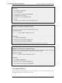
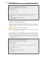
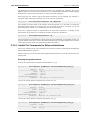
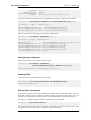
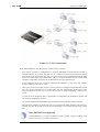
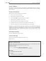
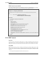
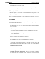
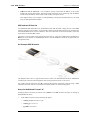
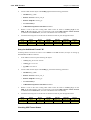
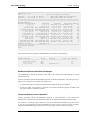
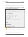
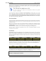
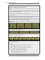
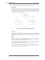
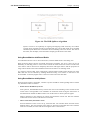
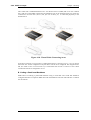
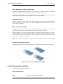
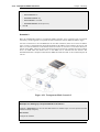
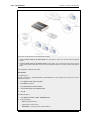
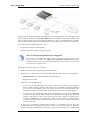
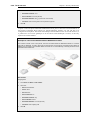
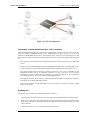
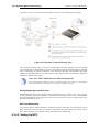
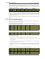
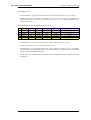
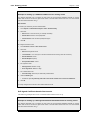
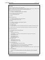
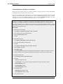
4.3.5. The Ordering parameter
Chapter 4. Routing
Example 4.5. Policy-based Routing Configuration
This example illustrates a multiple ISP scenario which is a common use of Policy-based Routing. The following is
assumed:
•
Each ISP will provide an IP network from its network range. A 2 ISP scenario is assumed in this case, with the
network 10.10.10.0/24 belonging to ISP A and 20.20.20.0/24 belonging to ISP B. The ISP provided gateways
are 10.10.10.1 and 20.20.20.1 respectively.
•
All addresses in this scenario are public addresses for the sake of simplicity.
•
This is a "drop-in" design, where there are no explicit routing subnets between the ISP gateways and the
NetDefend Firewall.
In a provider-independent network, clients will likely have a single IP address, belonging to one of the ISPs. In a
single-organization scenario, publicly accessible servers will be configured with two separate IP addresses: one
from each ISP. However, this difference does not matter for the policy routing setup itself.
Note that, for a single organization, Internet connectivity through multiple ISPs is normally best done with the BGP
protocol, which means not worrying about different IP spans or about policy routing. Unfortunately, this is not
always possible, and this is where Policy Based Routing becomes a necessity.
We will set up the main routing table to use ISP A and add a named routing table called r2 that uses the default
gateway of ISP B.
Interface
Network
lan1
10.10.10.0/24
Gateway
ProxyARP
wan1
lan1
20.20.20.0/24
wan2
wan1
10.10.10.1/32
lan1
wan2
20.20.20.1/32
wan1
all-nets
lan1
10.10.10.1
Contents of the named Policy-based Routing table r2:
Interface
Network
Gateway
wan2
all-nets
20.20.20.1
The table r2 has its Ordering parameter set to Default, which means that it will only be consulted if the main
routing table lookup matches the default route (all-nets).
Contents of the Policy-based Routing Policy:
Source
Interface
Source
Range
Destination
Interface
Destination
Range
Selected/
Service
Forward
VR table
Return
VR table
lan1
10.10.10.0/24
wan2
all-nets
wan2
all-nets
ALL
r2
r2
lan1
20.20.20.0/24
ALL
r2
r2
To configure this example scenario:
Web Interface
1.
Add the routes found in the list of routes in the main routing table, as shown earlier.
2.
Create a routing table called "r2" and make sure the ordering is set to "Default".
3.
Add the route found in the list of routes in the routing table "r2", as shown earlier.
4.
Add two VR policies according to the list of policies shown earlier.
•
Go to Routing > Routing Rules > Add > Routing Rule
•
Enter the information found in the list of policies displayed earlier
•
Repeat the above to add the second rule
168