1
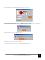
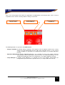
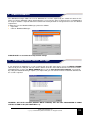
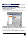
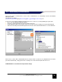
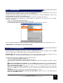
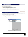
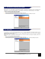
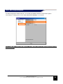
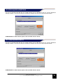
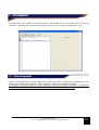
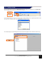
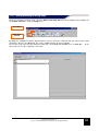
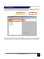
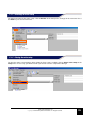
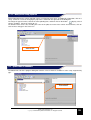
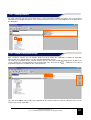
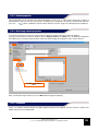
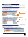
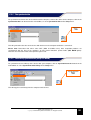
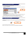
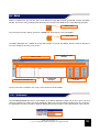
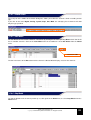
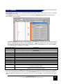
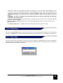
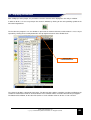
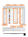
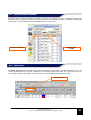
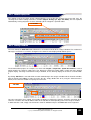
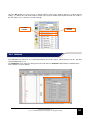
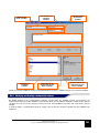
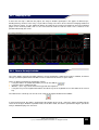
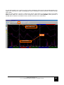
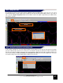
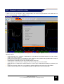
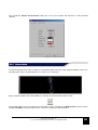
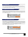
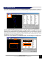
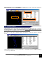
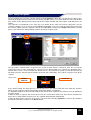
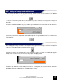
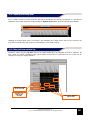
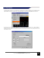
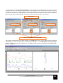
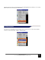
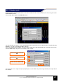
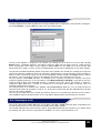
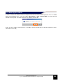
•
Type of calibration allows you to choose the type of calibration to use in the channel selected: A list of
types of calibration appears when you click on the button
with the left button of the mouse button. Make
the choice based on the type of channel you are working on: e.g. for potentiometer sensors choose Linear
The following types of calibration are available
Type of calibration
None
Linear
Description
No calibration: The channel is not calibrated
It is a linear type of channel and only the two values X and Y are needed to define the
characteristic
Step
The channel provides a “stepped” signal: Up to ten levels can be defined
Thermocouple
Channel connected to a thermocouple probe: calibration is not required
RPM
Channel connected to the ignition pickup: Provide the X value based on your engine
Speed
Channel connected to the proximity sensor applied to the wheel *
Time
Time type channel: calibration is not required
Latitude/Longitude
Latitude and longitude GPS data channel calibration is not required
Frequency
Channel connected to a variable frequency channel: calibration is not required
Accelerometer
Channel connected to an accelerometer: calibration is not required
NTC
Channel connected to a NTC sensor: calibration is not required
Voltage
Channel connected to a voltage signal: calibration is not required
Battery Voltage
Channel connected to the battery voltage: calibration is not required
RPM Spark
Channel is connected to a rpm sensor on the spark plug cable: enter the Coeff and Offset
values based on your engine
GEAR
Channel related to the gear ratio number entered: Enter the X (speed) and Y (rmp) values to
identify the gear entered in the vehicle
The value of speed varies according to the diameter of the tire used and the number of pulses per revolution
sent by the sensor placed on the wheel. Use the Calc Diameter function for sensors placed on the pinion: a
screen will open that will allow you to determine the values to enter to obtain a correct measurement of the
speed
•
•
Fields X, Y: Allows the association of the values read by the sensors (in the fields marked with X) to values
set by the user (in the fields marked with Y). This combination of values defines that calibration of the
channel. By clicking on an X field and then clicking the Capture button on the top right corner of the
Calibration dialog box, the current value of the channel (Y field) is associated to the previously selected X
field.
WARNING: The direct acquisition procedure described above must be made with the GET data
acquisition connected to a PC.
If there is no data acquisition device connected to a computer you can enter the values in the X and Y fields
manually using the keyboard.
NOTE: consult the instruction booklet of the sensor being calibrated to know the XY values to enter in the
appropriate fields
The Show in volts option, if enabled, shows the voltage of the channel expressed in volts.
6.5.5 Applying an offset
You can use the offset the button to specify a value to be added or subtracted to the value read from the
selected channel. Use negative values to subtract the offset from the channel and positive values to add offset,
confirm the data entered with the OK button.
GATE user manual rev. 03
Copyright ©2008 GET by Athena Evolution srl. All rights reserved
54