1
SERVICE MANUAL
FIELD SERVICE
2008.12
Ver. 2.0
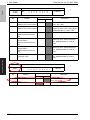
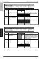
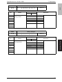
Revision history
After publication of this service manual, the parts and mechanism may be subject to change for
improvement of their performance.
Therefore, the descriptions given in this service manual may not coincide with the actual machine.
When any change has been made to the descriptions in the service manual, a revised version will be
issued with a revision mark added as required.
Revision mark:
• To indicate clearly a specific section revised within text, 1 is shown at the left margin of the
corresponding revised section.
The number inside 1 represents the number of times the revision has been made.
• To indicate clearly a specific page that contains a revision or revisions, the page number appearing at the left or right bottom of the specific page is marked with 1 .
The number inside 1 represents the number of times the revision has been made.
NOTE
Revision marks shown in a page are restricted only to the latest ones with the old ones deleted.
• When a page revised in Ver. 2.0 has been changed in Ver. 3.0:
The revision marks for Ver. 3.0 only are shown with those for Ver. 2.0 deleted.
• When a page revised in Ver. 2.0 has not been changed in Ver. 3.0:
The revision marks for Ver. 2.0 are left as they are.
Corresponded to a MAIN firmware version 21/
2008/12
2.0
1
Error corrections
2008/06
1.0
—
Issue of the first edition
Date
Service manual Ver.
Revision mark
Descriptions of revision
Field Service Ver. 2.0 Dec. 2008
FK-507
CONTENTS
FK-507
Outline
1.
Product specifications ............................................................................................. 1
2.
Other ....................................................................................................................... 5
2.1
Disassembly/adjustment prohibited items ............................................................ 5
FAXU board (with G3 multi port option) ................................................................ 6
3.2
Ni-MH battery replacement................................................................................... 8
Adjustment/Setting
4.
How to use the adjustment section ....................................................................... 11
5.
Utility Mode ........................................................................................................... 12
5.1
Utility Mode function tree .................................................................................... 12
5.2
Utility Mode function setting procedure............................................................... 14
5.2.1
Procedure ................................................................................................... 14
5.2.2
Exiting ......................................................................................................... 14
5.2.3
Changing the setting value in Utility Mode functions................................... 14
5.3
Settings in the User Settings .............................................................................. 15
5.3.1
5.4
Display Settings .......................................................................................... 15
Settings in the User Management ...................................................................... 15
5.4.1
Line Monitor Sound..................................................................................... 15
5.4.2
Memory RX ON/OFF .................................................................................. 15
5.5
Settings in the Admin. (Administrator Management) .......................................... 16
5.5.1
Document Management.............................................................................. 16
5.5.2
Fax Settings ................................................................................................ 17
5.5.3
TX Settings ................................................................................................. 18
5.5.4
RX Settings ................................................................................................. 18
5.5.5
Report Settings ........................................................................................... 19
5.5.6
Software Switch Setting .............................................................................. 20
5.6
Adjustment / Setting
3.1
Maintenance
Disassembly/assembly............................................................................................ 6
Settings in the Print Lists .................................................................................... 23
5.6.1
TX Report.................................................................................................... 23
5.6.2
RX Report ................................................................................................... 23
5.6.3
Bulletin List.................................................................................................. 23
i
Troubleshooting
3.
Outline
Maintenance
FK-507
Field Service Ver. 2.0 Dec. 2008
5.6.4
One-Touch List............................................................................................ 23
5.6.5
Program List ............................................................................................... 23
6.
Service Mode ........................................................................................................ 24
6.1
Service Mode function setting procedure ........................................................... 24
6.2
Service Mode function tree................................................................................. 25
6.3
Settings in the System Input............................................................................... 25
6.3.1
6.4
Settings in the List Output .................................................................................. 26
Outline
6.4.1
6.5
Maintenance
Protocol Trace............................................................................................. 26
Settings in the FAX Settings ............................................................................... 26
6.5.1
7.
Software Switch Setting.............................................................................. 25
Self-Telephone #......................................................................................... 26
Soft Switch ............................................................................................................ 27
7.1
Soft Switches Disclosed to Users (Screen Setting)............................................ 27
7.2
List of Defaults.................................................................................................... 31
7.3
List of Soft Switches ........................................................................................... 42
Troubleshooting
Troubleshooting
Adjustment / Setting
8.
ii
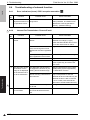
Troubleshooting..................................................................................................... 89
8.1
Diagnosis by alarm code .................................................................................... 89
8.2
Communication error codes ............................................................................... 90
8.2.1
Errors in operations .................................................................................... 90
8.2.2
Terminal alarm ............................................................................................ 91
8.2.3
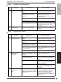
Communication errors (TX) ........................................................................ 91
8.2.4
Communication errors (RX) ........................................................................ 93
8.2.5
Malfunction ................................................................................................. 94
8.2.6
Internet Fax transmission / Scan to E-mail ................................................. 95
8.2.7
Internet Fax reception ................................................................................. 96
8.2.8
IP address Fax transmission....................................................................... 96
8.2.9
IP Relay ...................................................................................................... 97
8.2.10
Full mode communication........................................................................... 97
8.2.11
Scan to FTP transmission........................................................................... 98
8.2.12
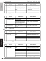
Scan to SMB Transmission......................................................................... 98
8.3
Diagnosis by symptoms...................................................................................... 99
8.4
Troubleshooting of network function ................................................................. 104
8.4.1
Error indications (Icons): POP3 reception anomalies .............................. 104
8.4.2
Internet Fax Transmission / Scan to E-mail .............................................. 104
8.4.3
IP address Fax Transmission.................................................................... 105
8.4.4
Internet Fax reception ............................................................................... 105
IP Relay..................................................................................................... 106
8.4.6
Scan to FTP .............................................................................................. 106
8.4.7
Scan to SMB ............................................................................................. 106
8.4.8
Assistant tool for C200 .............................................................................. 107
8.4.9
Others (Network device related) ............................................................... 109
Troubleshooting
Adjustment / Setting
Maintenance
Outline
8.4.5
FK-507
Field Service Ver. 2.0 Dec. 2008
iii
Troubleshooting
Adjustment / Setting
Maintenance
Outline
FK-507
Field Service Ver. 2.0 Dec. 2008
Blank Page
iv
Field Service Ver. 2.0 Dec. 2008
1. Product specifications
Outline
Product specifications
FK-507
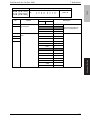
1.
A. Type
1
64 MB
Communication mode
G3/ECM
Scanning resolution
(main line x feed line)
8 x 3.85 line/mm
8 x 7.7 line/mm
8 x 15.4 line/mm
16 x 15.4 line/mm
Data transmission rate
G3 / ECM: 2.4 Kbps to 33.6 Kbps
Transmission rate
G3 / ECM: Image signal - 3 sec approx. (A4, V.34, 33.6 Kbps, JBIG)
Coding method
MH / MR / MMR / JBIG
Applicable network
G3/ECM
Options
Stamp unit SP-503
Fax multi line ML-504
Outline
Memory capacity
Phone line, FAX communication network
1
1
1. Product specifications
Field Service Ver. 2.0 Dec. 2008
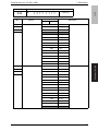
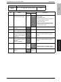
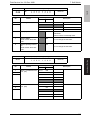
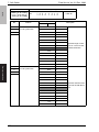
B. List of functions
FK-507
Function
Speed
Outline
Resolution
Operability
bizhub C200
High speed scanning
{
High speed printout
{ (20 ppm/A4)
ECM mode
{ (3 sec approx./Std document)
High speed half tone
{
Super fine mode
{
Half tone transmission
{
Auto retransmission after error
{ (ECM)
Brightness control
{
Smoothing
{
Mixed mode (Text + Photo)
{
One-touch dialing
{ (300 destinations)
One-touch program dialing
{ (30 destinations, # of one-touch dialing
numbers)
Auto re-dialing
{
Transmission booking
{ (64 destinations)
Broadcast destination
{ (210 destinations)
Origination selecting
{ (8 types)
Destination retrieval
{
LCD display
{ (320 x 240)
Operation
{ (Analog touch panel)
Disable copy function
{
Universal design
{
Enlarge display
Specify display location
{
Toner front access
{
2-in-1 printout
{
2-in-1 page transmission
{
TX marker
{ (Option)
Automatic document feed (ADF)
{ (70 sheets)
Automatic selection of print paper size {
Power source
saving & utility
functions
2
Password communication
{
Quick scan transmission
{
Priority transmission
{
Insert destination
{
Automatic pause for PSTN number
{
Display communication result
{
Record TSI information
{
ID display/record
{ (Received date and time record)
Power source saving mode
{
Print lamp
{
Sound volume
{ (Setup on screen; OFF/5 steps)
ADF 2 sided transmission
{
Field Service Ver. 2.0 Dec. 2008
1. Product specifications
{
Transmission report
{
Incompleted transmission report
{ (with document merge)
Serial broadcast report
{ (with document merge)
{
One-touch list
{
Fax program list
{
Bulletin board list
{
Setting list
{
Multi access
{ (Interrupt key exists)
Transmission booking document
number
{ (64 destinations)
Retransmission
{ (Destination changeable)
Document retransmission
{
Reception by memory
{
Outline
Report functions Account list
FK-507
bizhub C200
Function
Activity report (TX/RX)
Transmission management document
{ (48)
number
Memory
functions
1
1
System
configuration
Mutual
connectivity
Memory polling transmission
{
Confidential transmission
Confidential print
{ (F code)
Serial broadcast
{ (210 destinations; Full dial broadcast 12
(Included number))
Relay broadcast
{ (F code)
Automatic destination switching
{
Color → Black and White Fallback
{
Multi copy
{ (Sorting function)
Remote copy
{ (F code)
Quick memory transmission
{
File backup
{ (1H)
Rotated Rx
{
Extra telephone
{ (PB forwarding reception possible)*
*PSTN (Port 1 only)
Account track mode
{ (50 accounts)
Chain dialing
{
Multi-port
{ (Option)
Inch/mm conversion
{
Memory
{ (File memory 512 MB)
Paper feed cassette
{ (3100 sheets max.)
PC print
{
ITU-T G3/ECM
{
3
1
1. Product specifications
Field Service Ver. 2.0 Dec. 2008
Function
FK-507
1
bizhub C200
Remote diagnostics (CSRC)
{ (Terminal Dispatch)
Self diagnostics
{
Counter per application
{
In-file image data transmission
{
Switch display of communication error
{
code
{
Adjust touch panel registration
{
Adjust ADF zoom ratio (main/sub)
{
Adjust ADF registration (main/sub)
{
Adjust BS zoom ratio (main/sub)
{
Adjust BS registration (main/sub)
{
Check sensors
{
Adjust document size sensor
{
Adjust registration of printer engine
(main/sub)
{
Adjust mask of printer engine
(main/sub)
{
Adjust feeder loop of printer engine
(main/sub)
{
Test printing
{
Paper through test
{
Lock position
{
1
Internet Fax
{
1
IP address Fax
{ (B/W only)
1
Scan to E-mail
{
1
Scan to FTP
{
1
Scan to SMB
{
Outline
Change standard zoom ratio
Maintenance
Network function Document forwarding /
Archive distribution
1
{
1
LDAP search
{
Assistant tool for C200
{
Printer controller
{
1
1
{
IP relay
4
Field Service Ver. 2.0 Dec. 2008
2. Other
Maintenance
2.1
Other
FK-507
2.
Disassembly/adjustment prohibited items
B. Red-painted screws
NOTE
• The screws which are difficult to be adjusted in the field are painted in red in order
to prevent them from being removed by mistake.
• Do not remove or loosen any of the red-painted screws in the field. It should also
be noted that, when two or more screws are used for a single part, only one representative screw may be marked with the red paint.
C. Variable resistors on board
NOTE
• Do not turn the variable resistors on boards for which no adjusting instructions
are given in Adjustment/Setting.
D. Removal of PWBs
CAUTION
• When removing a circuit board or other electrical component, refer to “Handling of
PWBs” and follow the corresponding removal procedures.
• The removal procedures given in the following omit the removal of connectors and
screws securing the circuit board support or circuit board.
• Where it is absolutely necessary to touch the ICs and other electrical components
on the board, be sure to ground your body.
5
Maintenance
A. Paint-locked screws
NOTE
• To prevent loose screws, a screw lock in blue or green series color is applied to
the screws.
• The screw lock is applied to the screws that may get loose due to the vibrations
and loads created by the use of machine or due to the vibrations created during
transportation.
• If the screw lock coated screws are loosened or removed, be sure to apply a screw
lock after the screws are tightened.
3. Disassembly/assembly
3.
Disassembly/assembly
3.1
FK-507
Field Service Ver. 2.0 Dec. 2008
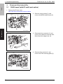
FAXU board (with G3 multi port option)
1. Remove the IR rear cover.
See P.46 of the main body service manual.
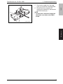
2. Remove seven screws [1], and
remove the MFBU shield cover [2].
[2]
[1]
[1]
Maintenance
A0F0F2C006DA
3. Disconnect the connector [1], and
remove the cable from two wire saddles [2] and the edge cover [3].
[1]
[2]
[3]
A0F0F2C007DA
4. Remove three screws [1], and
remove the FAX mounting plate [2].
[2]
[1]
A0F0F2C008DA
6
3. Disassembly/assembly
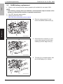
5. Remove the cable from the edge
cover [1] of the FAX mounting plate.
6. Disconnect the connector [2],
remove four screws [3], and remove
the FAXU board [4].
NOTE
• Connect the connector located on
the ferrite core side to the FAXU
board.
[3]
[4]
[1]
A0F0F2C009DA
Maintenance
[2]
FK-507
Field Service Ver. 2.0 Dec. 2008
7
3. Disassembly/assembly
3.2
Field Service Ver. 2.0 Dec. 2008
Ni-MH battery replacement
FK-507
1. Check on the screen that the memory capacity still available for use reads 100%.
NOTE
• If the memory capacity does not read 100%, let the machine output contents of the
memory or wait until the machine completes transmission.
2. Turn OFF the main power switch.
3. Remove the IR rear cover.
See P.46 of the main body service manual.
4. Remove seven screws [1], and
remove the MFBU shield cover [2].
Maintenance
[2]
[1]
[1]
A0F0F2C006DA
5. Disconnect the connector [1], and
remove the harness from the wire
saddle [2] and the edge cover [3].
[3]
[2]
[1]
A0F0F2C010DA
6. Tie band [1] is cut with nippers, and
the Ni-MH battery [2] is replace.
[1]
[2]
A0F0F2C011DA
8
Field Service Ver. 2.0 Dec. 2008
3. Disassembly/assembly
Maintenance
NOTE
• After the Ni-MH battery has been replaced with a new one, be sure to turn ON the
main power switch.
• Discard the used battery in accordance with the corresponding local regulations
and NEVER discard it or let it discharge on the user’s premises.
FK-507
7. Turn ON the main power switch.
9
Field Service Ver. 2.0 Dec. 2008
Maintenance
FK-507
3. Disassembly/assembly
Blank Page
10
Field Service Ver. 2.0 Dec. 2008
4. How to use the adjustment section
4.
How to use the adjustment section
• “Adjustment/Setting” contains detailed information on the adjustment items and procedures for this machine.
• Throughout this “Adjustment/Setting,” the default settings are indicated by “ ”.
FK-507
Adjustment/Setting
Advance checks
Before attempting to solve the customer problem, the following advance checks must be
made. Check to see if:
CAUTION
• To unplug the power cord of the machine before starting the service job procedures.
• If it is unavoidably necessary to service the machine with its power turned ON, use
utmost care not to be caught in the scanner cables or gears of the exposure unit.
• Special care should be used when handling the fusing unit which can be
extremely hot.
• The developing unit has a strong magnetic field. Keep watches and measuring
instruments away from it.
• Take care not to damage the PC drum with a tool or similar device.
• Do not touch IC pins with bare hands.
11
Adjustment / Setting
• The power supply voltage meets the specifications.
• The power supply is properly grounded.
• The machine shares the power supply with any other machine that draws large current
intermittently (e.g., elevator and air conditioner that generate electric noise).
• The installation site is environmentally appropriate: high temperature, high humidity,
direct sunlight, ventilation, etc.; levelness of the installation site.
• The original has a problem that may cause a defective image.
• The density is properly selected.
• The original glass, slit glass, or related part is dirty.
• Correct paper is being used for printing.
• The units, parts, and supplies used for printing (developer, PC Drum, etc.) are properly
replenished and replaced when they reach the end of their useful service life.
• Toner is not running out.
5. Utility Mode
5.
Utility Mode
5.1
FK-507
Field Service Ver. 2.0 Dec. 2008
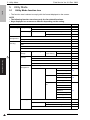
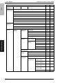
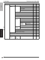
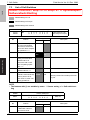
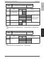
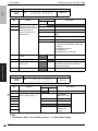
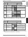
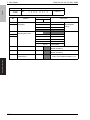
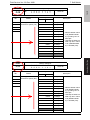
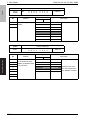
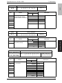
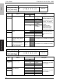
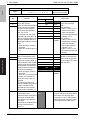
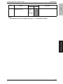
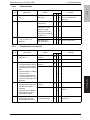
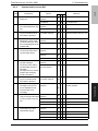
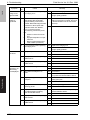
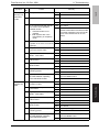
Utility Mode function tree
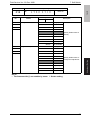
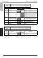
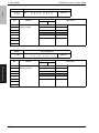
• The function tree is shown to comply with the format displayed on the screen.
NOTE
• The following function tree shows only the fax-related functions.
• Keys displayed on screens are different depending on the setting.
Utility
Ref. page
User Settings Display Settings Default Screen
*
Default Fax Screen
Default Settings Fax/Scan
P.15
Default Scan/Fax Settings
*
File Type
*
User
Management
Line Monitor Sound
P.15
Memory RX ON/OFF
P.15
One-Touch/
Box Reg.
One-Touch
*
Index
*
Domain Name
*
Bulletin
Admin.
Adjustment / Setting
1
*
System
Settings
Output Settings
One-Touch/
Box Reg.
One-Touch
Document
Management
Print/Fax
Printer
Output Setting Fax/E-Mail
*
*
*
Index
*
Domain Name
*
Bulletin
*
TX Forwarding
RX Document
P.16
All Other Docs. Password
RX Doc. Settings
P.16
Forwarding Dest.
Network/G3
Password
RX Doc. Settings
P.16
Forwarding Dest.
Reception user User Box Name
box
Type
Number
Password
P.17
RX Doc. Settings
Forwarding Dest.
Remote Input Check
Fax Settings
Self-ID
RX Functions
P.17
Reception Mode
P.17
Numbers of RX Call Rings
P.17
Password Communication
1
12
P.17
Field Service Ver. 2.0 Dec. 2008
5. Utility Mode
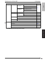
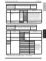
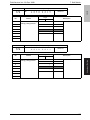
Utility
Fax Settings
Self-Telephone #
Information 1
Ref. page
Self-Telephone # 1
PBX Connect. Mode 1
Dialing Method 1
Self-Telephone #
Information 2
FK-507
Admin.
Self-Telephone # Info 2
P.18
PBX Connect. Mode 2
Dialing Method 2
TX Settings
TSI Registration
P.18
RX Settings
Memory RX Timer Memory RX Time
Setting
Memory Lock Password
P.18
Delete User Box
P.19
Report Settings TX Report
Activity Report
Print Lists
Print Lists
P.19
P.19
*
Software Switch Setting
P.20
TX Report
P.23
RX Report
P.23
Bulletin List
P.23
One-Touch List
P.23
Program List
P.23
*: For details, see the main body service manual.
Adjustment / Setting
1
Setting List
P.18
13
1
5. Utility Mode
FK-507
5.2
5.2.1
Field Service Ver. 2.0 Dec. 2008
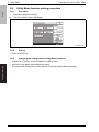
Utility Mode function setting procedure
Procedure
1. Press the Utility/Counter key.
2. The Utility Mode screen will appear.
A02FF3E516DA
5.2.2
Exiting
• Touch the [OK] key.
Adjustment / Setting
5.2.3
Changing the setting value in Utility Mode functions
• Use the [+] / [-] key to enter or change the setting value.
• Use the 10-key pad to enter the setting value.
(To change the setting value, first press the Clear key before making an entry.)
14
Field Service Ver. 2.0 Dec. 2008
Settings in the User Settings
5.3.1
Display Settings
FK-507
5.3
5. Utility Mode
A. Default Fax Screen
Functions
Use
Setting/
Procedure
• The default setting is “One-Touch”.
“One-Touch”
Search
Direct Input
Index
Settings in the User Management
5.4.1
Functions
Use
Setting/
Procedure
5.4.2
Functions
Use
Setting/
Procedure
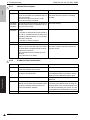
Line Monitor Sound
• To set the volume of the line monitor sound that can be heard from the monitor speaker
during fax transmission.
• The default setting is “3”.
0 (mute) to 5
Memory RX ON/OFF
• To allow the machine to produce a print temporarily even in the off mode.
• A print control password is necessary to print data.
1. Touch [Memory RX ON/OFF].
2. If a password has been specified, enter the password for “Memory Lock Password”
and touch [OK].
3. Touch [Lock OFF].
4. To halt the print cycle, touch [Lock ON] while the print cycle is being run.
5. Touch [Temporarily Print] to resume the print cycle.
Adjustment / Setting
5.4
• To set the screen which is preferentially displayed when in fax mode.
15
5. Utility Mode
FK-507
5.5
Field Service Ver. 2.0 Dec. 2008
Settings in the Admin. (Administrator Management)
• The Admin. setting will be available by entering the administrator password (8 digits) set
by the Admin. setting or Service Mode.
(The administrator password is initially set to “12345678.”)
5.5.1
Document Management
A. TX Forwarding
Functions
• To set to forward received text to a destination that has been set by the administrator.
Use
• When forwarding received text to a destination that has been set by the administrator.
Setting/
Procedure
1.
2.
3.
4.
5.
Touch [Document Management].
Touch [TX Forwarding].
Select the forwarding communication mode, and touch [Next].
Specify the forwarding destination, and touch [Next].
Check the forwarding destination, and touch [OK].
B. RX Document
(1) All Other Docs.
Functions
Use
Adjustment / Setting
Setting/
Procedure
• Specify the reception method for documents that were received normally.
1. Touch [RX Document].
2. Touch [All Other Docs.].
3. Touch [Password] and register the password.
New Password: Enter the new password to be used
Confirm New Password: Re-enter the new password
4. Touch [RX Doc. Settings], then select the desired processing type and touch [OK].
* If [Forward] or [Print & Forward] is selected, set the forwarding destination.
(2) Network/G3
Functions
Use
Setting/
Procedure
16
• A different reception method can be specified for each line.
1. Touch [RX Document].
2. Touch [Network], [G3-1] or [G3-2].
3. If [YES] is selected for document management, set how the received document is to
be handled.
4. Touch [Password] and register the password.
New Password: Enter the new password to be used
Confirm New Password: Re-enter the new password
5. Touch [RX Doc. Settings], then select the desired processing type and touch [OK].
* If [Forward] or [Print & Forward] is selected, set the forwarding destination.
Field Service Ver. 2.0 Dec. 2008
5. Utility Mode
Functions
• A reception user box specifically for documents containing special information, such as
Fcodes, can be created, and the reception method can be specified.
Use
1. Touch the [RX Document].
2. Touch the button of the user box to be specified.
3. Touch [User Box Name] and enter the user box name from the 10-key pad.
(A maximum of 8 characters can be entered.)
4. Touch [Type] and select the reception management type.
5. Touch [Number] and enter in the number appropriate for the reception type from the
10-key pad.
6. Touch [Password] and register the password.
New Password: Enter the new password to be used
Confirm New Password: Re-enter the new password
7. Touch [RX Doc. Settings], then select the desired processing type and touch [OK].
* If [Forward] or [Print & Forward] is selected, set the forwarding destination.
8. If F-codes are used, touch [Remote Input Check] and select whether remote input
checking is enabled or disabled.
Setting/
Procedure
5.5.2
FK-507
(3) Reception user box
Fax Settings
A. Self-ID
• To register the name, telephone number, and other information of the local machine as
an ID.
Use
• When the registered information is to be printed on journals and displayed on the panel
of the fax machine on the receiving end.
Setting/
Procedure
1. Touch the [Self-ID].
2. Enter the local machine ID (up to 12 characters) and touch [OK].
Adjustment / Setting
Functions
B. RX Functions
(1) Reception Mode
Functions
• To set the reception mode of faxes.
Use
• When changing the reception mode of faxes.
Setting/
Procedure
• The default setting is “Auto”.
“Auto”
Manual
(2) Numbers of RX Call Rings
Functions
• To set the number of call rings heard before automatic reception is activated.
Use
• When changing the number of call rings heard before automatic reception is activated.
Setting/
Procedure
• The default setting is “1x”.
1 to 20
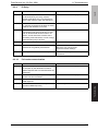
C. Password Communication
Functions
• To allow a fax to be received only when there is a match in the password that has previously been registered on the transmitter and receiver ends.
Use
• When using password reception.
Setting/
Procedure
• The default setting is “00”.
“00” (Disabled)
01 to 99 (Enabled)
17
5. Utility Mode
Field Service Ver. 2.0 Dec. 2008
FK-507
D. Self-Telephone # information
Functions
Use
Setting/
Procedure
5.5.3
• To register information required for fax communication, including the telephone number
of the local fax machine, whether or not a PBX is available, and the type of line.
1. Touch the [Self-Telephone # information].
2. Touch [Self-telephone #] and enter the telephone number.
3. Touch the [PBX Connect. Mode].
[Extension]: If a connection is made via the PBX to the ordinary fixed line
[Outside]: If a connection is made directly to the ordinary fixed line
* If [Extension] is selected, enter the Outside Line.
4. Touch the [Dialing Method].
[DP20]: 20 pps pulse dialing line
[DP10]: 10 pps pulse dialing line
[PB]: Tone dialing line
TX Settings
A. TSI Registration
Functions
• To set the name (of the sending party) to be notified to the recipient.
Use
• When changing the name (of the sending party) to be notified to the recipient.
Setting/
Procedure
• Up to eight different names can be registered.
1. Touch the [TSI Registration].
2. Select the number, for which the sending party is to be registered.
3. Enter the name of the sending party and touch [OK].
Adjustment / Setting
5.5.4
RX Settings
A. Memory RX Timer Setting
(1) Memory RX Time
Functions
• To set the time of day and the day of the week, at which printing of the received fax is to
be started or stopped.
Use
• When a received fax is to be printed at a specific time specified without allowing it to be
printed on the spot.
Setting/
Procedure
1. Touch the [Memory RX Timer Setting].
2. Touch the [Memory RX Time].
3. Make the necessary settings and touch [OK].
* Touch [OFF] if no settings are to be made.
(2) Memory Lock Password
Functions
Use
Setting/
Procedure
18
• To set a password used for printing a fax received at a time not specified.
1.
2.
3.
4.
Touch the [Memory RX Timer Setting].
Touch the [Memory Lock Password].
Touch [New Password], then enter the password and touch [OK].
Touch [Confirm New Password], then enter the password a second time and touch
[OK].
Field Service Ver. 2.0 Dec. 2008
5. Utility Mode
Functions
Use
Setting/
Procedure
5.5.5
FK-507
B. Delete User Box
• To delete a user box that has previously been registered.
1. Touch the [Delete User Box].
2. Select the private box to be deleted.
3. Touch the [Yes].
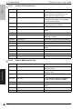
Report Settings
A. TX Report
Functions
• To set the mode of output of the report used for confirming results of transmission.
Use
• When changing the mode of output of the report used for confirming results of transmission.
• Setting is made individually for a single destination and two or more destinations.
Setting/
Procedure
<Single Dest>
ON
“If TX Fails”
OFF
<Broadcasting>
ON
“If TX Fails”
OFF
B. Activity Report
• To select whether or not to print the activity report for every 50 transactions automatically.
Use
• When printing the activity report for every 50 transactions automatically.
Setting/
Procedure
• The default setting is “ON”.
“ON”
OFF
Adjustment / Setting
Functions
19
5. Utility Mode
5.5.6
FK-507
Functions
Use
Setting/
Procedure
Field Service Ver. 2.0 Dec. 2008
Software Switch Setting
• To specify the value (mode, bit, HEX) for software DIPSW to suit the purpose of the
use, and to change the machine status.
• Only software DIPSW available of setting by the user (administrator) are described
here.
• For details of the software DIPSW as well as software DIPSW which can be set by
CE, refer to the “Service mode” or main body service manual.
1. Touch [Software Switch Setting].
2. Touch [Mode Selection], and enter the mode number (three digit number) using the
10-key pad.
3. Touch [Bit Selection].
4. Set the cursor using the [ ← ] or [ → ] key to specify the bit with 0 or 1 on the 10-key
pad. (When setting in hexadecimal, press [HEX Selection] to enter using the 10-key
pad or A to F key.)
5. Touch [Apply].
6. Touch [OK].
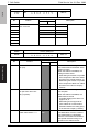
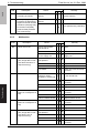
A. List of the software switch settings for administrator
(1) For network settings
Adjustment / Setting
Mode
• Specifying settings concerning the SMTP transmission timeout
357
• Specifying settings concerning the SMTP reception timeout
358
• Specifying settings concerning the POP3 reception timeout
361
• Specifying settings concerning Assistant tool for C200, SMTP transmission/reception
and POP3 reception
364
• Specifying the setting for the POP Before SMTP time
365
• Specifying settings concerning the timeout for a FTP connection
367
• Specifying settings concerning the timeout for a DNS inquiry
372
• Specifying settings concerning the transmission interval for divided e-mail messages
1
376
• Specifying settings concerning the AppleTalk protocol
1
378
• Specifying settings concerning the IPP printing
380
• Specifying security settings for e-mail transmissions
1
1
Setting item
356
383
• Specifying security settings for e-mail receptions
384
• Specifying settings concerning the network protocol
1
385
• Specifying settings concerning the SMB protocol
1
386
• Specifying settings concerning the TCP socket, NetWare
1
389
• Specifying settings concerning the encryption method for SSL and the SNMP protocol
1
390
• Specifying settings concerning the SNMP protocol
470
• Specifying settings concerning Assistant tool for C200
20
Field Service Ver. 2.0 Dec. 2008
5. Utility Mode
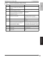
(2) For scan/fax settings
1
1
1
1
1
Setting item
• Specifying settings concerning the position of the transmission source information and
concerning password communications
001
• Specifying settings for inserting the recipient’s name in the original
002
• Specifying printing of the memory clear report and the report for a broadcast transmission
004
• Specifying the storage time for failed transmission documents
016
• Specifying whether or not a received date report is added and its format
023
• Specifying settings for the TWAIN operation lock time and the image in the results report
024
• Specifying settings for administrator forwarding
025
• Specifying settings concerning transmission if the memory becomes full
028
• Specifying the maximum number of copies allowed with remote copying
030
• Specifying settings for fax reception functions
037
• Specifying the settings for selecting paper trays when faxes are received
043
• Specifying settings for general subscriber lines
249
• Specifying settings for the number of rings until automatic reception (port 2)
301
• Specifying settings for receiving long documents
302
• Specifying the setting for selecting paper when printing received documents
350
• Specifying settings concerning Internet faxing
351
• Specifying transmission source information for IP address fax transmissions and IP relay
operations
352
• Specifying whether transmission source information is added when performing a IP relay
operation, or when forwarding received documents
360
• Coding method for the receiver Internet fax capability (Network function, Mail mode)
363
• Specifying settings concerning the from address in MDN/DSN reports
366
• Specifying the default address input screen
368
• Specifying settings concerning IP relay operations appearing in the activity report
373
• Specifying settings concerning full mode functions with Internet faxing
381
• Specifying the default setting for the coding method
382
• Specifying settings concerning the communication results of IP relay operations
391
• File format, Coding format
473
• Specifying the Job list screen given priority
476
• Specifying settings concerning the direct input tab and broadcast transmissions
477
• Fax registration restriction and destination display, Setting confirmation screen for broadcast TX
478
• Specifying settings concerning the use of the button for deleting, the display when a onetouch dial button is touched, and the default communication mode
804
• Specifying settings for checked receiver transmissions
Adjustment / Setting
000
FK-507
Mode
(3) For printer settings
Mode
304
Setting item
• Specifying the storage time for confidential documents
21
1
5. Utility Mode
Field Service Ver. 2.0 Dec. 2008
(4) For copy settings
Adjustment / Setting
FK-507
Mode
22
Setting item
402
• Specifying settings for the main application
403
• Specifying settings for using copy mode operations
417
• Specifying whether or not the number of copies are limited
471
• Specifying how the screen for selecting an account appears in administrator mode
501
• Specifying settings for enlarge display mode
835
• Specifying the setting concerning public accounts
Field Service Ver. 2.0 Dec. 2008
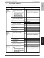
Settings in the Print Lists
5.6.1
TX Report
FK-507
5.6
Functions
• The TX report can be printed.
Use
• To output the report provided a record of transmission jobs such as document number,
start time, time, destination, mode, page, size to check it.
Setting/
Procedure
1. Touch [Print Lists].
2. Touch [TX Report].
3. TX report is output.
5.6.2
RX Report
Functions
• The RX report can be printed.
Use
• To output the report provided a record of reception jobs such as document number,
start time, time, destination, mode, page, size to check it.
Setting/
Procedure
1. Touch [Print Lists].
2. Touch [RX Report].
3. RX report is output.
5.6.3
Functions
Bulletin List
• The bulletin list can be printed.
Use
• To output the document list registered on the bulletin boards to check it.
Setting/
Procedure
1. Touch [Print Lists].
2. Touch [Bulletin List].
3. Bulletin list is output.
5.6.4
Functions
One-Touch List
• The one-touch list can be printed.
Use
• To output the registered one-touch list to check it.
Setting/
Procedure
1. Touch [Print Lists].
2. Touch [One-Touch List].
3. One-touch list is output.
5.6.5
Adjustment / Setting
1
5. Utility Mode
Program List
Functions
• The program list can be printed.
Use
• To output the selected program content to check it.
Setting/
Procedure
1.
2.
3.
4.
Touch [Print Lists].
Touch [Program List].
Touch the fax program that wants to output.
Program list is output.
23
1
6. Service Mode
FK-507
6.
6.1
Field Service Ver. 2.0 Dec. 2008
Service Mode
Service Mode function setting procedure
NOTE
• Ensure appropriate security for Service Mode function setting procedures. They
should NEVER be shown to any unauthorized person not involved with service
jobs.
A.
1.
2.
3.
Procedure
Press the Utility/Counter key.
Touch [Check Details].
Press the following keys in this order.
Stop → 0 → 0 → Stop → 0 → 1
NOTE
• When selecting [CE Authentication] under [Security Settings] available from Service Mode, authentication by CE password is necessary.
Enter the 8 digits CE password, and touch [END].
(The initial setting for CE password is “92729272.”)
• NEVER forget the CE password. When forgetting the CE password, it becomes
necessary to replace the RAMU board with a new one and call responsible person
of KMBT.
• The service code entered is displayed as “*.”
Adjustment / Setting
4. The Service Mode menu will appear.
A02FF3E517DA
NOTE
• Be sure to change the CE password from its default value.
• For the procedure to change the CE password, see the Security Settings.
B. Exiting
• Touch the [OK] key.
NOTE
• When changing the setting value in service mode, make sure to turn main power
switch off once and turn it on again.
C. Changing the setting value in Service Mode functions
• Use the [+] / [-] key to enter or change the setting value.
• Use the 10-key pad to enter the setting value.
(To change the setting value, first press the Clear key before making an entry.)
24
Field Service Ver. 2.0 Dec. 2008
6.2
6. Service Mode
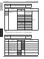
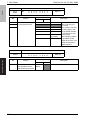
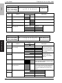
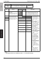
Service Mode function tree
FK-507
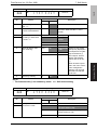
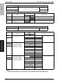
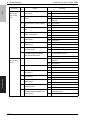
• The function tree is shown to comply with the format displayed on the screen.
NOTE
• The following function tree shows only the fax-related functions.
• Keys displayed on screens are different depending on the setting.
Ref.
page
Service Mode
System Input
Memory Clear
*
Software Switch Setting
P.25
P.27
Counter
Fax Connection Error
*
List Output
Protocol Trace
P.26
State Confirmation
Machine Configuration
*
Fax Settings
Self-Telephone #
P.26
*: For details, see the main body service manual.
6.3
Settings in the System Input
Software Switch Setting
Functions
Use
Setting/
Procedure
• To change the status of each function by setting values (mode, bit, HEX) for soft
switch of the machine as necessary.
• Refer to the corresponding item on [Admin.] for the list of the soft switches available
of setting by the user (administrator).
See P.20
1. Call the Service Mode on the screen.
2. Touch [System Input] → [Software Switch Setting].
3. Touch [Mode Selection], and enter the mode number (three digit number) using the
10-key pad.
4. Touch [Bit Selection].
5. Set the cursor using [ ← ] or [ → ] key, and set the bit with 0 or 1 on the 10-key pad.
(When setting in hexadecimal, press [HEX Selection], and enter on the 10-key pad
or A to F keys.)
6. Touch [Apply].
7. Touch [OK].
A. Software Switch
Mode
Bit
HEX
• Each parameter is expressed as a three-digit number.
Use the keypad to type in the value.
• The bits are the eight numbers that represent the parameter status.
By specifying a binary number (0 or 1) for each of the bits (0 through 7), settings for
each parameter can be specified.
• Specify a setting for each mode as a hexadecimal number (0 through 9 and A
through F). Bit setting “0011 0000” is expressed as the hexadecimal setting “30.”
• Specify the status of each parameter by using either bits or hexadecimal values.
25
Adjustment / Setting
6.3.1
6. Service Mode
FK-507
6.4
Settings in the List Output
6.4.1
Protocol Trace
Functions
Use
Setting/
Procedure
6.5
Field Service Ver. 2.0 Dec. 2008
• To produce an output of a protocol information during fax transmission.
1. Call the Service Mode on the screen.
2. Touch [List Output] → [Protocol Trace].
3. Press the start key to print the report.
Settings in the FAX Settings
6.5.1
Self-Telephone #
• It is displayed only when bit2 for the mode 043 is set to “1” by the following setting:
[Service Mode] → [System] → [Software Switch Setting].
Functions
Use
Adjustment / Setting
Setting/
Procedure
26
• To register the telephone number of the local fax machine.
1. Touch [Self-Telephone #].
2. Select the key for the self-telephone # to be regist.
3. Enter the self-telephone # from the 10-key pad, and touch [OK].
Field Service Ver. 2.0 Dec. 2008
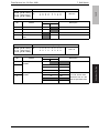
Soft Switch
User
Settings
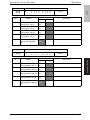
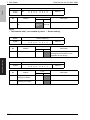
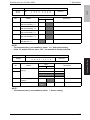
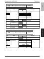
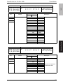
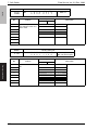
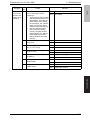
Soft Switches Disclosed to Users (Screen Setting)
System
Settings
FK-507
7.1
Utility
Mode
bit
Language Selection
820
7 to 2
Priority Tray
408
7 to 4
Auto Tray Switch ON/OFF
403
1
No Matching Paper in Tray Setting
409
0
400
5 to 3
Measurement Unit Setting
Paper Tray
Setting
Paper Type/Size Setting
Auto Color Level Adjustment
Dehumidify Scanner
Display
Settings
Default Screen
493
1, 0
Default Fax Screen
476
5, 4
Default
Settings
Copy
IP Relay Dest. Selection
382
2 to 0
File Type
Full Color
391
7, 6
Gray Scale
391
5
Black
391
4
424
3
Fax/Scan
Default Scan/Fax Settings
Copier Settings Small Originals
Auto Zoom for Combine
403
7
Auto Sort/Group Selection
412
3
Printer Settings Basic Settings PDL Setting
440
7, 6
Number of Copies
442
7 to 0
Original Direction
441
3, 2
Document Hold Time
457
7 to 0
Paper Tray
441
7 to 4
Paper Size
440
5 to 0
2-Sided Print
443
7
Bind Position
443
6, 5
A4/A3 <--> LTR/LGR Auto Switch
Paper
Settings
PCL Settings
Font #
444
7 to 1
Symbol Set
445
7 to 2
Font Size
447
448
449
450
451
7
7 to 0
3 to 0
7 to 0
5 to 0
Line/Page
446
7 to 0
CR/LF Mapping
Print Reports
Configuration Page
PCL Demo Page
PCL Font List
27
Adjustment / Setting
7.
7. Soft Switch
7. Soft Switch
Field Service Ver. 2.0 Dec. 2008
FK-507
Utility
User
Settings
Printer Settings Print Reports
Mode
bit
492
7 to 5
492
4 to 2
PS Font List
User
Confirmation Beep
Management Alarm Volume
Line Monitor Sound
493
7 to 5
Job Complete Beep
494
4 to 2
038
1
Panel Cleaning
Dehumidify
POP3 RX
Memory RX ON/OFF
One-Touch/
Box Reg.
One-Touch
Index
Domain Name
Bulletin
Admin.
System
Settings
Power Save
Settings
Output
Settings
Auto Reset
448
7 to 0
Low Power Mode Settings
489
7 to 0
Sleep Mode Settings
490
7 to 0
LCD Back-Light OFF
491
7 to 0
Enter Power Save Mode
883
3
Print/Fax
Printer
Output Setting Fax/E-Mail
301
0
Adjustment / Setting
Output Tray
Setting
Copy
305
2
Printer
305
0
Network
309
0
Fax (Port 1)
305
1
Fax (Port 2)
309
1
821
7 to 2
354
7 to 2
400
5 to 3
Language (I/O)
Date & Time
Setting
Date & Time Setting
Time Zone
Daylight Saving Time
Expert
Adjustment
AE Level Adjustment
Density
Adjustment
Thick Paper Image
Density -Yellow
Thick Paper Image
Density -Magenta
Thick Paper Image
Density -Cyan
Thick Paper Image
Density -Black
Black Image Density
28
Field Service Ver. 2.0 Dec. 2008
7. Soft Switch
Utility
System
Settings
Expert
Adjustment
Image
Stabilization
Mode
bit
455
456
7 to 0
1, 0
Initialize +
Stabilization
FK-507
Admin.
Image Stabilization
Color Reg.
Adjustment
Cyan
Magenta
Yellow
Gradation
Adjustment
Copy
Printer (Gradation)
Printer (Resolution)
Printer
Adjustment
1
Media Adjustment
Paper Size/Type Counter
1
One-Touch/Box One-Touch
Reg.
Index
Domain Name
Bulletin
Administrator
Settings
1
Administrator Password
Activity Report E-Mail TX
Call Remote Center
Account Track
Authentication Account Track
Settings
Allow Print Without Auth.
Document
Management
TX Forwarding
RX Document
Printer Settings Timeout
Fax Settings
Adjustment / Setting
Account Track Account Track Registration
Settings
All Counter Clear
Self-ID
RX Functions Reception Mode
Number of RX Call Rings
Password Communication
1
SelfTelephone #
Information
Self-Telephone # 1
SelfTelephone #
Information 2
Self-Telephone # Info 2
PBX Connect Mode 1
086
2
Dialing Method 1
086
5, 4, 3
PBX Connect Mode 2
116
2
Dialing Method 2
116
5, 4, 3
038
1, 0
002
6, 5
002
7
TX Settings
TSI Registration
RX Settings
Memory RX
Memory RX Time
Timer Setting Memory Lock Password
Delete User Box
Report Settings TX Report
Activity Report
29
1
7. Soft Switch
Field Service Ver. 2.0 Dec. 2008
Utility
FK-507
Admin.
Print Lists
Setting List
Network
Settings
Basic Settings DHCP
Mode
bit
355
4
355
7, 6, 5
361
0
IP Address
Subnet Mask
Gateway
Network Board Set
DNS Settings
Machine Name
SMTP TX Settings
SMTP RX Settings
POP3 Settings
Scanner
Settings
Activity Report
352
7
RX Doc. Header Print
353
6
E-Mail Header Text
353
7, 4
Binary Division
371
1
Binary Division Size
351
7
387
5 to 3
Subject Registration
Division
Settings
Gateway TX
1
LDAP
Settings
Setting Up LDAP
1
Frame Type Set
Search Default Setting
Adjustment / Setting
IP Relay Settings
RAW Port Number Settings
Software Switch Setting
Ping
Firmware Version
Security
Settings
1
30
Function
Mgmt
Settings
Maximun Job Allowance
Field Service Ver. 2.0 Dec. 2008
1
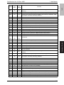
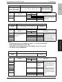
MODE
HEX
(For
U.S.)
HEX
(For
Europe)
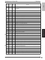
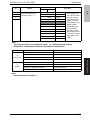
000
30
20
001
00
00
Dest. insert
002
A8
A8
Reports *
003
43
43
Broadcast TX result report *
004
06
06
Memory time *
005
04
08
(Undefined)
006
00
00
(Undefined)
007
F0
F0
G3-1 non-selectable cassette
008
F0
F0
G3-2 non-selectable cassette
009
F0
F0
Network non-selectable cassette
010
F0
F0
Reports non-selectable cassette
011
00
00
(Undefined)
012
00
00
(Undefined)
013
05
01
Automatically switch destinations, Operation when INBOX forward fails
FK-507
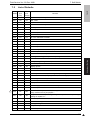
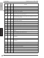
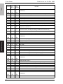
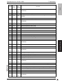
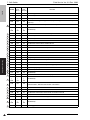
List of Defaults
Remark
TSI, Password, Memory TX *
014
00
00
(Undefined)
015
8A
8A
Color, Resolution, Quality *
016
11
11
FLS-Legal switching, Reception date printing *
017
00
00
Select initial value of TSI *
018
46
46
Density setting, Background adjustment *
019
00
00
(Undefined)
020
40
40
Display reports
021
80
80
(Undefined)
022
00
00
Zoom ratio for TX *
TWAIN operation lock time, Set merge for report image *
023
38
38
024
D1
D1
Forward function button, Display caller ID, No receiving by other users *
025
40
40
Processing when memory overflow occurs
Adjustment / Setting
7.2
7. Soft Switch
026
00
00
(Undefined)
027
04
04
Display ID, Secured comm., F code, 2in1 TX
028
63
63
Remote copy protocol, # of remote multi-copies *
029
00
00
(Undefined)
030
D1
D0
Rotate TX, Rotate print, 2in1 RX, Print paper selection restriction,
assign mixed mm/inch print papers *
031
A0
A0
Merge for multi-sheet report image, Merge for output format of report image,
Binding for duplex TX *
032
00
00
(Undefined)
033
00
00
2-sided TX setting *
034
02
02
Overlap printing
035
03
03
RX by memory
036
00
00
(Undefined)
31
1
7. Soft Switch
FK-507
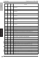
MODE
1
Adjustment / Setting
32
HEX
(For
Europe)
Remark
037
F8
F8
Select FAX print paper cassette *
038
0A
0A
Setting stop/start printing *
039
00
00
(Undefined)
040
FE
FE
Binary coding, T.6 coding, JBIG, V.34JBIG
ECM mode, Audio response
041
40
40
042
3F
3F
Redialing interval
043
83
83
# of resending doc., Redialing non-answered call, No. of rings, TSI/CSI registration, PSTN port automatic selection *
044
82
82
RTN sending error trace threshold, TX special processing, T4 timer, Action
against abnormal overseas communications, RTN reception processing,
V.34 control channel retrain
045
10
20
Number of redialing times
28
Line holding guard timer, Symbol rate display, EQM value monitoring, Probing information monitoring
V.34 fallback tolerance
046
1
HEX
(For
U.S.)
Field Service Ver. 2.0 Dec. 2008
28
047
88
88
048
C7
C7
Set up MODEM standard, Redialing interval for broadcast TX
049
0D
0D
Transmission speed upper limit (TX)
050
0D
0D
Transmission speed upper limit (RX)
051
21
21
Declare RX print paper size
052
00
00
(Undefined)
053
48
48
Document processing when F-CODE reception fails
054
7A
7A
Silence detection time, History control of V.34 auto dialing, Demodulation
method
055
02
02
Silence detection, Silence detection level
056
0C
0C
Select sending time of ANSam
057
19
19
Time that ANSam TX starts after line is blocked
058
|
069
3C
|
1A
3C
|
1A
(Undefined)
070
14
14
Pseudo-ringer sound
071
|
076
00
|
14
00
|
14
(Undefined)
077
60
60
Hook monitoring adjustment times during ringer
078
00
00
(Undefined)
079
02
02
(Undefined)
080
23
6E
Line connection time (PSTN1)
081
00
00
(Undefined)
082
34
34
Detect busy tone, Line monitoring, Detect line disconnection (PSTN1)
083
50
50
Hook monitoring cycle, Hook detection voltage (PSTN1)
084
14
28
PB sending lever (PSTN1)
085
90
C0
TX level (PSTN1)
MODE
HEX
(For
U.S.)
HEX
(For
Europe)
Remark
086
4C
4C
RX attenuator (PSTN1), DP speed, PB/DP switching, Internal/external line
switching
087
90
90
Detect continuous ringer, Ringer detection frequency (PSTN1)
088
C0
C0
Process to be carried out when 2nd dialing tone timeout is detected, 1300
Hz reception sensitivity switching (PSTN1)
089
00
00
Posed insertion, Prefix # (PSTN1) *
090
00
00
(Undefined)
091
00
00
(Undefined)
092
70
70
Sending echo protection tone, Switch carrier frequency (PSTN1)
093
88
40
CED, Receive command echo (PSTN1)
094
0C
0C
AGC lock (PSTN1)
095
20
20
Digital TX/RX cable equalizer (PSTN1)
096
14
14
CI signal sending time (PSTN1)
097
14
14
TCF/NTCF sending level down, V.34 symbol rate (PSTN1)
098
46
46
CM signal sending start time, EQM threshold value (PSTN1)
099
88
88
V.34 symbol rate threshold value (PSTN1)
100
|
109
00
|
00
00
|
00
(Undefined)
110
23
6E
Line connection time (PSTN2)
111
00
00
(Undefined)
112
24
24
Detect busy tone, Detect line disconnection (PSTN2)
113
50
50
(Undefined)
114
14
28
PB sending lever (PSTN2)
115
90
C0
TX level (PSTN2)
116
4C
4C
RX attenuator, DP speed, PB/DP switching, Internal/external line switching
(PSTN2)
117
90
90
Detect continuous ringer, Ringer detection frequency (PSTN2)
118
C0
C0
Process to be carried out when 2nd dialing tone timeout is detected, 1300
Hz reception sensitivity switching (PSTN2)
119
00
00
Posed insertion, Prefix # (PSTN2) *
120
00
00
(Undefined)
121
00
00
(Undefined)
122
70
70
Sending echo protection tone, Switch carrier frequency (PSTN2)
123
88
40
CED, Receive command echo (PSTN2)
124
0C
0C
AGC lock (PSTN2)
125
20
20
Digital TX/RX cable equalizer (PSTN2)
126
14
14
CI signal sending time (PSTN2)
127
14
14
TCF/NTCF sending level down, V.34 symbol rate (PSTN2)
128
46
46
CM signal sending start time, EQM threshold value (PSTN2)
129
88
88
V.34 symbol rate threshold value (PSTN2)
33
FK-507
7. Soft Switch
Adjustment / Setting
Field Service Ver. 2.0 Dec. 2008
Adjustment / Setting
FK-507
7. Soft Switch
MODE
HEX
(For
U.S.)
HEX
(For
Europe)
130
|
211
00
|
02
00
|
02
(Undefined)
Remark
212
40
00
DP make rate (PSTN1)
213
|
231
00
|
05
00
|
02
(Undefined)
232
40
00
DP make rate (PSTN2)
233
|
248
00
|
51
00
|
51
(Undefined)
249
08
08
Ringer detection counts (PSTN2) *
250
|
287
08
|
FF
08
|
FF
(Undefined)
288
FF
FF
Insert dummy data before PIX
289
|
299
FF
|
00
FF
|
00
(Undefined)
300
41
41
Stamp, Trim print paper leading edge, Remote copy print order
301
19
15
Print image reduction, Division *
302
00
00
Print paper selection *
303
00
00
(Undefined)
304
00
00
Confidential document holding time, Print lamp lighting, etc. *
305
05
05
ADF density adjustment, Output pin *
306
00
00
(Undefined)
307
00
00
(Undefined)
308
00
00
Specify Imaging unit life stop, Normal stabilization, Specify next print color
mode operation, Take data for image stabilization
309
00
00
Output tray setting *
310
00
00
(Undefined)
311
00
00
(Undefined)
1
312
20
20
Setting printing area for ADF front side leading edge 1 (A)
1
313
07
07
Setting printing area for ADF front side leading edge 2 (B)
314
21
21
Setting printing area for ADF front side posterior end 1 (C)
315
00
00
Setting printing area for ADF front side posterior end 2 (D)
316
80
80
ACS parameter setting for ADF front side leading edge (2) *
317
10
10
ACS parameter setting for ADF front side posterior end (3) *
1
1
Field Service Ver. 2.0 Dec. 2008
318
00
00
ACS parameter setting (1) for ADF front side center (1) *
1
319
20
20
Setting printing area for ADF back side leading edge 1 (A)
1
320
07
07
Setting printing area for ADF back side leading edge 2 (B)
321
21
21
Setting printing area for ADF back side posterior end 1 (C)
322
00
00
Setting printing area for ADF back side posterior end 2 (D)
34
Field Service Ver. 2.0 Dec. 2008
7. Soft Switch
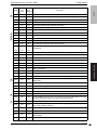
MODE
HEX
(For
U.S.)
HEX
(For
Europe)
323
80
80
ACS parameter setting for ADF back side leading edge (2) *
324
10
10
ACS parameter setting for ADF back side posterior end (3) *
325
00
00
ACS parameter setting for ADF back side center (1) *
326
00
00
ACS Parameter setting for the book scanner *
327
64
64
Main scan direction size detection threshold
328
03
03
Wait time after lamp lights until main scan direction size detection starts
329
19
19
Main scan direction size detection threshold
1
330
01
01
Wait time after cover closes until main scan direction size detection starts
1
331
60
60
Scan minimum value when cover is closed
1
332
80
80
Scan maximum value when cover is opened
333
1E
1E
Re-shading interval (first time)
334
3C
3C
Re-shading interval (since the second times)
335
|
349
00
|
00
00
|
00
(Undefined)
1
1
1
350
28
28
POP3 before SMTP TX, Document width/line density upper limit *
351
1C
1C
Gateway transmission, IP address fax reception, SMTP reception *
352
D0
D0
Notification of result, Add TSI for Gateway TX and forwarding *
353
88
80
Text insertion, Header printing *
354
38
60
Time zone *
355
30
30
Switch 10M/100M, Switch full-duplex/half-duplex, DHCP *
SMTP TX timeout *
356
20
20
357
A0
A0
SMTP receive timeout *
358
20
20
POP3 receiving timeout *
359
00
00
Set re-trials for forwarding RX docs, Forced priority TX
360
80
80
Coding method for the receiver Internet fax capability (Network function,
Mail mode) *
FK-507
Adjustment / Setting
1
Remark
361
F8
F8
DNS function *
362
8A
8A
Intervals for calling on the network *
363
40
40
SMTP expansion prohibited, Specify from address for DNS report *
364
05
05
POP before SMTP time *
365
02
02
FTP timeout
366
08
08
Priority address input for scan, Anonymous e-mail countermeasure, E-mail
file name character restrict, File name year digit quantity *
367
00
00
Time of DNS inquiry timeout *
368
82
82
Activity report, Activity report for scanner TX (TX), RX result management
for IP relay sending machine *
(Undefined)
369
00
00
370
FF
FF
Additional # of TX re-trials
371
40
40
Interval of retrials to be set for additional # of TX re-trials, Binary division,
Page division *
372
0F
0F
Transmission interval of size-divided e-mail file data *
35
1
FK-507
7. Soft Switch
MODE
HEX
(For
U.S.)
HEX
(For
Europe)
373
08
08
374
50
50
NOTIFY setting
375
00
00
(Undefined)
NetWare, NDS/Bindery, AppleTalk *
Remark
Full mode function, MDN correspondence *
1
376
00
00
1
377
FF
FF
Printer number for Nprinter/Rprinter mode *
1
378
FF
FF
IPP setting *
379
00
00
Edit data when forwarding received documents
380
3A
3A
APOP authentication, SMTP authentication, HTTP server, SSL *
381
80
80
IP relay function *
382
40
40
IP relay result timeout processing, Default station *
SMTP authentication reception *
383
38
38
384
FF
FF
TCP/IP, LPD, RAW port, FTP, SNMP *
1
385
C0
C0
Scan setting, print setting *
1
386
30
30
TCP Socket, NetWare *
387
00
00
LDAP
Adjustment / Setting
1
Field Service Ver. 2.0 Dec. 2008
388
00
00
Ethernet frame type *
389
0C
0C
Coding method, Allow write, Allow discovery user *
390
A4
A4
Read security level, Write security level, PDF profile reception limitation,
JPEG compression method *
391
00
00
File format, Coding format *
392
|
399
00
|
00
00
|
00
(Undefined)
400
10
10
Priority doc. mixed mode, Priority auto color level, Priority color *
401
00
00
2 colors, Mono color
402
04
04
Average density, Priority copy mode, Automatic function priority mode, Priority application, Neg./Pos. reverse *
403
00
00
Draft print zoom ratio, Sorting, AMS setting for tray selection, Copy function
use *
404
4C
4C
Background adjustment, Glossy copy *
1
405
40
40
Character reproduction, document binding, frame erase *
1
406
00
00
Erase position (book separation), binding margin
407
00
00
(Undefined)
408
00
00
Default tray (print paper) *
36
409
04
04
Default 4-in-1 print order, Priority document quality, Non-matching specified
feed trays *
410
00
00
(Undefined)
411
00
00
(Undefined)
412
08
08
Priority sort mode, Sort/group *
413
48
48
Copy density *
414
|
416
70
|
00
70
|
00
(Undefined)
Field Service Ver. 2.0 Dec. 2008
1
MODE
HEX
(For
U.S.)
HEX
(For
Europe)
417
00
00
Set max # of copies *
418
|
423
00
|
00
00
|
00
(Undefined)
424
00
00
Small doc. *
425
10
10
Select FLS size
426
10
00
(Undefined)
427
48
48
Brightness for color quality adjustment *
428
48
48
Contrast for color quality adjustment *
429
48
48
Saturation for color quality adjustment *
430
48
48
Red for color quality adjustment *
431
48
48
Green for color quality adjustment *
432
48
48
Blue for color quality adjustment *
433
48
48
Yellow for color quality adjustment *
434
48
48
Magenta for color quality adjustment *
435
48
48
Cyan for color quality adjustment *
436
48
48
Black for color quality adjustment *
437
60
60
Sharpness for color quality adjustment *
438
00
00
(Undefined)
439
00
00
(Undefined)
440
0B
01
Set PCL, Paper size *
441
80
80
Paper tray, Paper orientation *
442
01
01
# of copies (least significant 8 bits) *
443
20
20
Printing method, # of copies (most significant 2 bits) *
444
00
00
Language code *
445
78
4C
Symbol set *
446
3C
40
# of lines *
447
00
00
Unit of font size *
448
30
30
Font size (Scalable) (least significant 8 bits) *
Font size (Scalable) (most significant 4 bits) *
FK-507
Remark
Adjustment / Setting
1
7. Soft Switch
449
00
00
450
E8
E8
Font size (Bitmap) (least significant 8 bits) *
451
03
03
Font size (Bitmap) (most significant 6 bits) *
452
80
80
Switch A4/Letter, feed cassette fixed/priority, CR/LF mapping, allow printing
without account authentication *
453
00
00
Set PostScript error print *
454
03
03
(Undefined)
455
3C
3C
Timeout set (least significant 8 bits) *
456
00
00
Timeout set (most significant 2 bits) *
457
05
05
Memory overflow waiting time *
458
04
04
PC print job deletion operation, PC-FAX job deletion operation *
37
1
Adjustment / Setting
FK-507
7. Soft Switch
38
Field Service Ver. 2.0 Dec. 2008
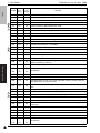
MODE
HEX
(For
U.S.)
HEX
(For
Europe)
459
|
469
00
|
00
00
|
00
(Undefined)
470
00
00
Set export extension, Simple format, PSDA use, Auto logout time *
471
01
00
Set user's list screen display and default screen *
472
00
00
(Undefined)
473
40
40
Set priority job list screen, Use of # for destination entry *
474
00
00
(Undefined)
475
00
00
(Undefined)
476
00
00
Destination display screen, Specify full-dial TX, Specify broadcast TX *
477
01
01
Fax registration restriction and destination display, Setting confirmation
screen for broadcast TX *
478
82
02
Specify delete key operation, Display when pressing one-touch, Comm.
mode initial value, Antidew processing, PB/DP auto detection key *
Remark
479
00
00
(Undefined)
480
00
00
Display file forwarding key, Sound patterns for alarm buzzer
481
|
484
00
|
00
00
|
00
(Undefined)
485
C0
00
Year/Month/Day display order
486
40
40
Daylight saving time activation switch
487
00
00
No sleep
488
01
01
Auto reset *
489
0A
0A
Low power mode *
490
14
14
Sleep mode *
491
01
01
LCD back-light OFF *
492
6C
6C
Sound volume setting (buzzer sound, alarm sound) *
493
64
68
Sound volume setting (monitor sound), Priority application screen *
494
0C
0C
Sound volume setting (completion sound) *
495
|
499
00
|
00
00
|
00
(Undefined)
500
00
00
Enlarge sound volume *
501
00
00
Screen reverse, Next screen display for enlarge display *
502
03
03
Key repeat starting time *
503
01
01
Key repeat interval *
504
03
03
Reservation completion screen display *
505
40
40
Buzzer sound *
506
00
00
Extend auto reset time *
507
|
511
00
|
00
00
|
00
(Undefined)
512
80
80
Dial tone detection
Field Service Ver. 2.0 Dec. 2008
7. Soft Switch
MODE
HEX
(For
U.S.)
HEX
(For
Europe)
513
|
517
64
|
01
64
|
0A
518
D4
D4
Setting the voice message
00
Setting to allow/prohibit fax operation when detecting an error during voice
message
00
FK-507
(Undefined)
520
01
01
Ringer detection counts (PSTN1)
521
|
767
1E
|
0A
1E
|
14
(Undefined)
768
0C
0C
Soft time adjustment value (V.17, V.27 ter)
769
07
07
Soft time adjustment value (V.29)
770
1C
C2
CFR-PIX interval
771
23
23
T1 timer for auto-TX
772
23
23
T1 timer for auto-RX
773
23
23
T1 timer for manual TX
774
23
23
T1 timer for manual RX
775
23
23
T1 timer for auto-TX of polling
776
23
23
T1 timer for manual TX of polling
777
07
07
PIX-Post command interval
778
|
803
00
|
01
00
|
02
(Undefined)
804
04
04
SF/SSF communication, Destination machine confirmation TX *
805
53
53
Special characters for destination machine confirmation TX
806
|
819
00
|
00
00
|
00
(Undefined)
820
04
04
Language code (for display)
821
04
04
Language code (for input/output)
822
00
00
(Undefined)
823
04
04
Language code (for input)
824
|
829
80
|
00
80
|
00
(Undefined)
830
50
60
Total counter count mode, Paper size considered as the large size
1
831
00
00
Key counter
1
832
00
00
Vendor + key counter, management device management setting
1
833
00
00
Vendor message, PC print control with key counter
1
834
00
00
(Undefined)
835
00
00
Public account *
836
|
879
00
|
00
00
|
00
(Undefined)
Adjustment / Setting
519
Remark
39
1
FK-507
7. Soft Switch
Adjustment / Setting
MODE
HEX
(For
U.S.)
HEX
(For
Europe)
880
70
10
881
00
00
(Undefined)
882
E0
E0
Warm-up mode *
883
04
00
Power save setting, LCT paper size, Optional original size detection (Book
scanner)
Remark
Unit change, Consumable life reminder
884
01
01
Fan control for the low-temperature warm-up
885
|
900
E0
|
00
E0
|
00
(Undefined)
1
901
01
01
CS Remote Care: Line for send only, Dial mode
1
902
73
73
(Undefined)
1
903
0A
0A
(Undefined)
1
904
02
02
CS Remote Care transmission mode
1
905
03
03
CS Remote Care modem redial interval
1
906
0A
0A
CS Remote Care modem redial times
1
907
01
01
CS Remote Care redial for response timeout
1
908
06
06
CS Remote Care retransmission interval on E-mail error
1
909
0A
0A
CS Remote Care retransmission times on E-mail error
1
910
00
00
CS Remote Care time zone
1
911
20
20
Ring reception → Connect reception timer
1
912
40
40
Dial call end → Connect reception timer
1
913
00
00
(Undefined)
1
914
20
20
Line Connect → Send start-up message request time
1
915
1E
1E
Opposite party signal answer wait time
1
916
00
00
(Undefined)
1
917
00
00
(Undefined)
1
918
01
01
CS Remote Care ATTENTION display
1
919
|
929
00
|
00
00
|
00
(Undefined)
1
930
00
00
CS Remote Care
Authentication, SMTP authentication information
1
931
05
05
CS Remote Care POP before SMTP time
1
932
20
20
CS Remote Care SMTP timeout
1
933
1E
1E
CS Remote Care POP3 server auto connection interval
1
934
20
20
CS Remote Care POP3 timeout
1
935
00
00
CS Remote Care APOP setting
1
936
|
940
00
|
00
00
|
00
(Undefined)
1
941
F0
F0
FIFO trigger level
1
1
Field Service Ver. 2.0 Dec. 2008
40
Field Service Ver. 2.0 Dec. 2008
7. Soft Switch
MODE
HEX
(For
U.S.)
HEX
(For
Europe)
1
942
|
944
00
|
00
00
|
00
(Undefined)
1
945
C1
C1
CS Remote Care
Unit of the timer for awaiting toner empty restoration
1
946
|
999
00
|
00
00
|
00
(Undefined)
Adjustment / Setting
FK-507
Remark
41
1
7. Soft Switch
FK-507
7.3
Field Service Ver. 2.0 Dec. 2008
List of Soft Switches
NOTE
Utilità> ContrDett> Stop> 0> 0> Stop> 0> 1> SystemImput>
• If no bit settings are given in the soft switch list that follows, the factory settings
SoftwareSwitchSetting
for those particular bits are fixed and should never be changed.
: Default settings of U.S.
: Default settings of Europe
: Default settings are common
MODE
000
Adjustment / Setting
Bit
Factory setting bit
Bit:
7 6 5 4
0 0 1 1
3 2 1 0
0 0 0 0
Logic
Feature
0
1
5
Specifies whether printOFF
ing TSI on transmitted
document is returned to
ON or OFF after completing operations. <*>
ON
4
Select position of TSI. <*> Out of
Doc.
On the
Doc.
3
Specifies whether confirming communication
password at TX is
returned to ON or OFF
after completing operations. <*>
OFF
ON
2
Confirm communication
password at RX. <*>
No
Yes
1
Specifies which TX
Memory- Quick
method is returned to ON, stored
scan
memory-stored TX or
quick scan TX, after completing operations. *
HEX: 30 (For U.S.)
HEX: 20 (For Europe)
Description
Memory-stored TX includes quick memory TX.
NOTE
• The features with (*) are settable by users. *: Screen setting <*>: Soft switch setting
MODE
001
Bit
0
42
Factory setting bit
Bit:
7 6 5 4
0 0 0 0
Logic
Feature
Specify whether to insert
a destination name on
document to send.
3 2 1 0
0 0 0 0
0
No
1
Yes
HEX: 00
Description
Field Service Ver. 2.0 Dec. 2008
002
Bit
7
6
5
Factory setting bit
Bit:
7 6 5 4
1 0 1 0
3 2 1 0
1 0 0 0
HEX: A8
Logic
Feature
0
Print communication
activity report automatically for every 50 activities. *
Description
1
No
FK-507
MODE
7. Soft Switch
Yes
“No” means manual print.
Select when a result
Bit 6-5:
report should be printed. *
00
No print
01
Print for
incomplete TX Specifies result reports
Always print
for TX, incomplete TX,
or broadcasting TX.
Not available
10
11
3
Print memory clear report. No
<*>
Yes
2
Log management of
broadcast transmissions.
<*>
Individual
All
together
MODE
003
Bit
7
6
Adjustment / Setting
NOTE
• The features with (*) are settable by users. *: Screen setting <*>: Soft switch setting
Factory setting bit
Bit:
Feature
7 6 5 4
0 1 0 0
3 2 1 0
0 0 1 1
HEX: 43
Logic
0
Result report of broadcast Bit 7-6:
transmissions. *
Description
1
00
No output
01
Output for
incomplete TX
10
Always output
11
Not available
NOTE
• The features with (*) are settable by users. *: Screen setting
43
7. Soft Switch
Field Service Ver. 2.0 Dec. 2008
FK-507
MODE
004
Bit
3
2
Factory setting bit
Bit:
7 6 5 4
0 0 0 0
3 2 1 0
0 1 1 0
Logic
Feature
0
Description
1
Selects holding time of
Bit 3-0:
incompleted TX document
in memory. <*>
0000
1
0
Adjustment / Setting
HEX: 06
0
Delete file from memory immediately (No
redialing function)
0001
10 min
0010
20 min
0011
30 min
0100
40 min
0101
50 min
0110
1 hr
0111
2 hr
1000
4 hr
1001
8 hr
1010
12 hr
1011
24 hr
1100
72 hr
Others
Not available
IC memory
device
NOTE
• The features with (*) are settable by users. <*>: Soft switch setting
MODE
007
Bit
44
Factory setting bit
Bit:
7 6 5 4
1 1 1 1
Feature
3 2 1 0
0 0 0 0
Logic
0
1
7
Cassette-specified
printing (G3-1: Tray 1)
Cannot
print
Can print
6
Cassette-specified
printing (G3-1: Tray 2)
Cannot
print
Can print
5
Cassette-specified
printing (G3-1: Tray 3)
Cannot
print
Can print
4
Cassette-specified
printing (G3-1: Tray 4)
Cannot
print
Can print
3
Cassette-specified
printing (G3-1: Bypass
tray)
Cannot
print
Can print
0
Cassette selection
per reception port
Disable
Enable
HEX: F0
Description
Field Service Ver. 2.0 Dec. 2008
Bit
7 6 5 4
1 1 1 1
3 2 1 0
0 0 0 0
Logic
Feature
0
1
7
Cassette-specified
printing (G3-2: Tray 1)
Cannot
print
Can print
6
Cassette-specified
printing (G3-2: Tray 2)
Cannot
print
Can print
5
Cassette-specified
printing (G3-2: Tray 3)
Cannot
print
Can print
4
Cassette-specified
printing (G3-2: Tray 4)
Cannot
print
Can print
3
Cassette-specified
printing (G3-2: Bypass
tray)
Cannot
print
Can print
MODE
009
HEX: F0
Description
Factory setting bit
Bit:
7 6 5 4
1 1 1 1
3 2 1 0
0 0 0 0
Logic
Bit
Feature
7
Cassette-specified
printing (Network: Tray 1)
Cannot
print
Can print
6
Cassette-specified
printing (Network: Tray 2)
Cannot
print
Can print
5
Cassette-specified
printing (Network: Tray 3)
Cannot
print
Can print
4
Cassette-specified
printing (Network: Tray 4)
Cannot
print
Can print
3
Cassette-specified
Cannot
printing (Network: Bypass print
tray)
0
1
HEX: F0
Description
Adjustment / Setting
008
Factory setting bit
Bit:
FK-507
MODE
7. Soft Switch
Can print
45
7. Soft Switch
Field Service Ver. 2.0 Dec. 2008
FK-507
MODE
010
Bit
Factory setting bit
Bit:
7 6 5 4
1 1 1 1
3 2 1 0
0 0 0 0
Logic
Feature
0
7
Cassette-specified
printing (Report: Tray 1)
Cannot
print
Can print
6
Cassette-specified
printing (Report: Tray 2)
Cannot
print
Can print
5
Cassette-specified
printing (Report: Tray 3)
Cannot
print
Can print
4
Cassette-specified
printing (Report: Tray 4)
Cannot
print
Can print
3
Cassette-specified
printing (Report: Bypass
tray)
Cannot
print
Can print
MODE
013
Adjustment / Setting
Bit
46
1
HEX: F0
Description
Factory setting bit
Bit:
7 6 5 4
0 0 0 0
Feature
3 2 1 0
0 1 0 1
Logic
0
1
HEX: 05 (For U.S.)
HEX: 01 (For Europe)
Description
2
Automatically switch
destinations.
OFF
ON
You can register main addresses and
2ndary addresses with onetouch. You
can send to 2ndary addresses when
communication with main addresses is
abnormal.
0
Select operation when
INBOX forward failed.
Destroy
document
immediately
Destroy
document
after
printing
Specify the action to be taken when
INBOX forwarding has failed. (Failed
means communications cannot be delivered. Communications means communication via FAX and E-mail.)
Field Service Ver. 2.0 Dec. 2008
Bit
7
7 6 5 4
1 0 0 0
3 2 1 0
1 0 1 0
0
Color default value *
Bit 7-6:
00
Resolution default value * Bit 5-3:
4
3
2
Quality default value *
Description
1
6
5
HEX: 8A
Logic
Feature
Bit 2-0:
FK-507
015
Factory setting bit
Bit:
Black
01
Gray scale
10
Full color
11
Not available
000
200 x 100 dpi
001
200 dpi
010
300 dpi
011
400 dpi
100
600 dpi
Others
Not available
000
Text
1
001
Photo
0
010
Text/Photo
011
Dot matrix
100
Map
Others
Not available
Specify default value of
color when transmitting.
Specify default value of
resolution when transmitting.
Specify default value of
quality when transmitting.
Adjustment / Setting
MODE
7. Soft Switch
NOTE
• The features with (*) are settable by users. *: Screen setting
MODE
016
Bit
Factory setting bit
Bit:
7 6 5 4
0 0 0 1
3 2 1 0
0 0 0 1
Logic
Feature
0
1
HEX: 11
Description
7
Switch FLS-Legal
FLS
Legal
5
Mail mode: Print date &
time received <*>
No
Yes
4
Mail mode: Position of
printing date & time
received <*>
Outside
of document
Inside of
Available when bit 5 of mode 016 is set
docuto “Yes”
ment
1
RX time stamp: Print date No
& time received <*>
Yes
0
RX time stamp: Position
of printing date & time
received <*>
Inside of Available when bit 1 of mode 016 is set
docuto “Yes”
ment
Used for G3 communications.
Outside
of document
Switches the detected size.
NOTE
• The features with (*) are settable by users. <*>: Soft switch setting
47
7. Soft Switch
Field Service Ver. 2.0 Dec. 2008
FK-507
MODE
017
Bit
3
Factory setting bit
Bit:
Feature
7 6 5 4
0 0 0 0
3 2 1 0
0 0 0 0
HEX: 00
Logic
0
Select initial value of TSI * Bit 3-0:
Description
1
0000
TSI 1
2
0001
TSI 2
1
0010
TSI 3
0
0011
TSI 4
0100
TSI 5
0101
TSI 6
0110
TSI 7
0111
TSI 8
Others
Not available
Adjustment / Setting
NOTE
• The features with (*) are settable by users. *: Screen setting
48
Field Service Ver. 2.0 Dec. 2008
Bit
7
7 6 5 4
0 1 0 0
Feature
HEX: 46
Logic
0
0000
1 (Light)
0001
2
5
0010
3
4
0011
4
Background adjustment *
Bit 7-4:
Description
1
6
3
Density *
3 2 1 0
0 1 1 0
Bit 3-0:
FK-507
018
Factory setting bit
Bit:
0100
5 (Standard)
0101
6
0110
7
0111
8
1000
9 (Dark)
Others
Not available
0000
-6 (Light)
2
0001
-5
1
0010
-4
0
0011
-3
0100
-2
0101
-1
0110
0 (Standard)
0111
+1
1000
+2 (Dark)
1001
Auto
Others
Not available
Specify default value of
density.
Specify default value of
background adjustment.
NOTE
• The features with (*) are settable by users. *: Screen setting
49
Adjustment / Setting
MODE
7. Soft Switch
7. Soft Switch
Field Service Ver. 2.0 Dec. 2008
FK-507
MODE
020
Bit
Factory setting bit
Bit:
3 2 1 0
0 0 0 0
HEX:40
Logic
Feature
0
Description
1
7
Displays # of reports.
No
Yes
“Yes” displays # of pages on phone line
in addition to ordinary # of papers.
6
Trace protocol.
No
Yes
“Yes” prints result of protocol trace after
completing communication. If next communication is proceeded before this
printing, information on previous communication protocol will be deleted.
5
Display number of error
No
lines/transmission speed.
Yes
“Yes” displays # of error lines/transmission speed on touch panel and outputs
port for auto checking.
4
Select monitor interval for Phase A
line.
All
phases
Specifies interval for monitoring phone
lines for G3 communication.
3
Display error codes.
(Reports)
Yes
“Yes” displays error codes (6 digits) in
reports.
MODE
022
Adjustment / Setting
7 6 5 4
0 1 0 0
Bit
5
No
Factory setting bit
Bit:
Feature
7 6 5 4
0 0 0 0
3 2 1 0
0 0 0 0
HEX: 00
Logic
0
Zoom setting default value Auto
for TX *
zoom
1
No
reduction
NOTE
• The features with (*) are settable by users. *: Screen setting
50
Description
Field Service Ver. 2.0 Dec. 2008
Bit
7 6 5 4
1 1 0 1
3 2 1 0
0 0 0 1
0
TX forwarding to adminis- Disable
trator. <*>
Enable
6
TX forwarding of scanner
function to administrator.
<*>
Disable
Enable
5
Report output when TX
forwarding to administrator is set. <*>
Bit 5-4:
2
Select ID display order
when receiving.
Bit 2-1:
1
00
Not output
Output when
TX fails
10
Always output
11
Not available
00
Expansion ID Determine the subject
→ TSI
data priority displayed in
the subject line for gateTSI
way transmission (*)
Not available when Report, Screen
display and Network
options are set to Yes.
(*)
When forward is specified in the user’s “Document management”
settings, and received
facsimile is broadcast
via E-mail.
01
Receive by memory.
No
Valid when Mode 024 Bit 7 is set to
“Enable.”
01
Others
0
Description
1
7
4
HEX: D1
Logic
Feature
FK-507
024
Factory setting bit
Bit:
Yes
NOTE
• The features with (*) are settable by users. <*>: Soft switch setting
MODE
025
Bit
7
6
Factory setting bit
Bit:
7 6 5 4
0 1 0 0
Feature
Memory overflow
transmission mode
3 2 1 0
0 0 0 0
HEX: 40
Logic
0
Bit 7-6:
Description
1
00
Quit transmission
01
Inquire (Quit TX for non-response
and quick memory TX)
10
Inquire (Continue TX for non-response
and quick memory TX)
11
Not available
51
Adjustment / Setting
MODE
7. Soft Switch
7. Soft Switch
Field Service Ver. 2.0 Dec. 2008
FK-507
MODE
027
Bit
7
6
5
Factory setting bit
Bit:
7 6 5 4
0 0 0 0
3 2 1 0
0 1 0 0
HEX: 04
Logic
Feature
0
Description
1
Bit 7-5:
Select ID display order:
Specifies priority order of
destination IDs for printing
report/displaying on
screen. Secure comm.
with N-method
000
Pattern 1: 1→2→3→4
001
Pattern 2: 3→4→1→2
010
Pattern 3: 3→1→2→4
011
“CSI” → “called destination #” display
order
100
Pattern 4: 2→1→4
Others
Not available
Adjustment / Setting
1: Name registered in one-touch button
or phone # of destination dialed (full
dialing)
2: Destination phone #
3: Extended ID
4: Standard ID (# of TSI/CIG)
3
Secure comm. with Nmethod
No
2
F code function
Disable
Enable
Used for G3 communications.
1
Assign non-reduction TX
for 2in1 scan.
No
Yes
Specify whether 2in1 TX will be sent by
A4 always or by size appropriate to
receiver’s capability.
0
Specify 2in1 TX
No
Yes
MODE
028
Bit
1
Yes
Factory setting bit
Bit:
7 6 5 4
0 1 1 0
Feature
3 2 1 0
0 0 1 1
HEX: 63
Logic
0
Description
1
7
Select remote copy protocol. F code
N method
6
Select restricted number of
prints of remote copy. <*>
0000000
Not available
(Same as 1 copy)
0000001
1 copy
5
4
3
Bit 6-0:
|
2
1100011
99 copies
1
Others
Not available
(Same as 99
copies)
0
NOTE
• The features with (*) are settable by users. <*>: Soft switch setting
1
52
Field Service Ver. 2.0 Dec. 2008
7. Soft Switch
Bit
7 6 5 4
1 1 0 1
3 2 1 0
0 0 0 1
HEX: D1 (For U.S.)
HEX: D0 (For Europe)
Logic
Feature
0
Description
1
7
Rotation TX *
No
6
Rotate print of FAX RX.
<*>
No rotate Rotate
print
print
4
Receive 2in1 page.
(Valid for RX print) <*>
No
Yes
3
Restrict print paper
selection:
Specifies unselectable
print paper (including
orientation) for FAX.
Bit 3-2:
00
No B5S, A5S,
and postcard
01
No A5S and
postcard
2
1
0
Assign mixed mm/inch
print papers.
(Priority set)
(Valid for RX printing or
report printing)
FK-507
030
Factory setting bit
Bit:
Yes
Bit 1-0:
10
No postcard
11
Not available
00
Select mm only
01
Select inch only
10
Select both
11
Not available
NOTE
• The features with (*) are settable by users. *: Screen setting <*>: Soft switch setting
MODE
031
Bit
Factory setting bit
Bit:
7 6 5 4
1 0 1 0
3 2 1 0
0 0 0 0
HEX: A0
Logic
Feature
0
Description
1
7
Margin process for multiple copies of report with
image merge.
No
Yes
6
Assign output format for
image marge report.
Same as
regular
report
Always
A5 forma
5
Margin layout for 2-sided
TX *
Top
margin
Left
margin
Valid when “Set marge for report image.
(MODE 023 Bit 3)” is set to “Yes.”
1: Always output with A5 format regardless of the set status of print paper.
This is valid when a cassette has A4
print paper and not A4S print paper.
NOTE
• The features with (*) are settable by users. *: Screen setting
53
Adjustment / Setting
MODE
7. Soft Switch
Field Service Ver. 2.0 Dec. 2008
FK-507
MODE
033
Bit
6
Factory setting bit
Bit:
7 6 5 4
0 0 0 0
3 2 1 0
0 0 0 0
HEX: 00
Logic
Feature
0
Initial setting of 2-sided
TX *
Description
1
No 22-sided
sided-TX TX mode
mode
NOTE
• The features with (*) are settable by users. *: Screen setting
MODE
034
Bit
Adjustment / Setting
1
Factory setting bit
Bit:
7 6 5 4
0 0 0 0
Logic
Feature
0
Overlap printing.
No
MODE
035
Bit
54
3 2 1 0
0 0 1 0
1
Yes
HEX: 02
Description
Valid only at RX printing.
Overlapped print is fixed to 4 mm
regardless of line density.
Factory setting bit
Bit:
7 6 5 4
0 0 0 0
3 2 1 0
0 0 1 1
Logic
Feature
0
1
1
RX by memory when
reaching I/C lifetime.
No
Yes
0
RX by memory when
reaching toner empty.
No
Yes
HEX: 03
Description
Field Service Ver. 2.0 Dec. 2008
037
Bit
Factory setting bit
Bit:
7 6 5 4
1 1 1 1
3 2 1 0
1 0 0 0
HEX: F8
Logic
Feature
0
Description
1
7
Select FAX paper cassette (1st cassette). <*>
No
Yes
6
Select FAX paper cassette (2nd cassette). <*>
No
Yes
5
Select FAX paper cassette (3rd cassette). <*>
No
Yes
4
Select FAX paper cassette (4th cassette). <*>
No
Yes
2
Select FAX paper cassette (Bypath). <*>
No
Yes
FK-507
MODE
7. Soft Switch
NOTE
• The features with (*) are settable by users. <*>: Soft switch setting
• If bits 7-4 and bit 2 all are set to “No,” 1st cassette is forcibly selected.
038
Bit
3
2
Factory setting bit
Bit:
7 6 5 4
0 0 0 0
HEX: 0A
Logic
Feature
Print restart timer after
stopping.
3 2 1 0
1 0 1 0
0
Bit 3-2:
Description
1
00
3 min
01
5 min
10
10 min
11
20 min
1
Manual setting of print
stop/start. *
Stop
Start
0
Print stop/start timer. *
Does not
function
Function
Adjustment / Setting
MODE
NOTE
• The features with (*) are settable by users. *: Screen setting
55
7. Soft Switch
Field Service Ver. 2.0 Dec. 2008
FK-507
MODE
040
Factory setting bit
Bit:
Adjustment / Setting
Bit
7 6 5 4
1 1 1 1
HEX: FE
Logic
Feature
0
Description
1
7
2-dim coding at TX.
No
(Valid for G3 communication)
Yes
“No”: MH
“Yes”: MH + MR
6
T.6 coding.
No
(Valid for G3 communication)
Yes
“Yes”: MH + MR + MMR
Valid only when “2-dim coding at TM.
(MODE 040 Bit 7)” is set to “Yes.”
5
JBIG communication.
(Valid for ECM communication)
No
Yes
4
Third party’s JBIG (ITU-T)
communication.
(Valid for ECM communication)
No
Yes
3
Proprietary JBIG (ITU-T)
communication.
(Valid for ECM communication)
No
Yes
1
JBIG capability at V.34 communication. (G3)
No
Yes
MODE
041
Bit
56
3 2 1 0
1 1 1 0
Valid only when “JBIG communication. (MODE 040 Bit 5)” is set to
“Yes.”
Valid only when “JBIG communication. (MODE 040 Bit 5)” is set to
“Yes.”
Valid only when “JBIG communication. (MODE 040 Bit 5)” is set to
“Yes.”
Factory setting bit
Bit:
7 6 5 4
0 1 0 0
3 2 1 0
0 0 0 0
Logic
Feature
0
1
6
ECM mode
No
Yes
1
Audio response
Disable
Enable
HEX:40
Description
“No”: G3
“Yes”: G3 + ECM
Field Service Ver. 2.0 Dec. 2008
Bit
7
Feature
7 6 5 4
0 0 1 1
3 2 1 0
1 1 1 1
HEX: 3F
Logic
0
Select redialing interval 1. Bit 7-4:
Description
1
0000
Not available
0001
1 min
5
0010
2 min
4
0011
3 min
0100
4 min
0101
5 min
0110
6 min
0111
7 min
1000
8 min
1001
9 min
1010
10 min
1011
11 min
1100
12 min
1101
13 min
1110
14 min
1111
15 min
6
3
Select redialing interval 2. Bit 3-0:
FK-507
042
Factory setting bit
Bit:
0000
Not available
2
0001
1 min
1
0010
2 min
0
0011
3 min
0100
4 min
0101
5 min
0110
6 min
0111
7 min
1000
8 min
1001
9 min
1010
10 min
1011
11 min
1100
12 min
1101
13 min
1110
14 min
1111
15 min
Adjustment / Setting
MODE
7. Soft Switch
57
7. Soft Switch
Field Service Ver. 2.0 Dec. 2008
FK-507
MODE
043
Bit
7
6
7 6 5 4
1 0 0 0
0
Bit 7-6:
Description
1
00
0
01
1
10
2
11
3
Redialing when line is
No
connected but no answer.
Yes
3
No. of rings until
transmission.
Not
restrict
(0 to 20
times)
Restrict
(2 to 4
times)
TCI/CSI registration
screen.
User
setting
Service
mode
setting
Select PSTN port
automatically.
Specify how to dial standard phone lines. <**>
No
Yes
1
HEX: 83
Logic
Feature
# of document
resendings.
3 2 1 0
0 0 1 1
4
2
Adjustment / Setting
Factory setting bit
Bit:
Number of times for automatic reception calls.
Set self-telephone # information.
When the system has 2 PSTN lines
and one of them is used, you can use
the other line by selecting “Yes.”
If you have only 1 PSTN line or wish to
use 2 lines for the extension and the
external lines separately, select “No.”
NOTE
• The features with (*) are settable by users. <*>: Soft switch setting
The feature with (**) is available only in a machine with a multi-port option.
58
Field Service Ver. 2.0 Dec. 2008
Bit
7 6 5 4
1 0 0 0
3 2 1 0
0 0 1 0
Logic
Feature
0
1
7
Select threshold value for 32 lines
RTN sending error trace. or more
64 lines
or more
6
Process TCF sending
specially.
Yes
4
Select T4 timer.
3 sec
(Action against line delay)
4.5 sec
3
Take an action against
No
communication error from
overseas. (Action against
LMCD-OFF)
Yes
Take an action against
No
communication error from
overseas.
(Action for fall back)
Yes
1
Process RTN RX failure.
No
(discard
as error)
Yes
(not as
error)
0
Retrain V. 34 control
channel.
No
(discard
as error)
Yes
(answer)
2
No
FK-507
044
Factory setting bit
Bit:
HEX: 82
Description
Specifies # of error lines as reference of
sending RTN:
• “32 lines or more”:
MCF if error lines are 0 to 31 RTN if
error lines are 32 or more
• “64 lines or more”:
MCF if error lines are 0 to 31 RTP if
error lines are 32 to 63 RTN if error
lines are 64 or more
Select “No” unless bad line is experienced.
Select “No” unless bad line is experienced.
Changes high-speed signal sending timing:
0: DCF/TCF 80 ms, CFR/PIX 450 ms
1: DCF/TCF 250 ms, CFR/PIX 600 ms
59
Adjustment / Setting
MODE
7. Soft Switch
7. Soft Switch
Field Service Ver. 2.0 Dec. 2008
FK-507
MODE
045
Bit
7
6
5
Factory setting bit
Bit:
Feature
7 6 5 4
0 0 0 1
3 2 1 0
0 0 0 0
Logic
0
Select number of
Bit 7-4:
redialings 1.
(Number of auto redialing
at 1st stage)
Adjustment / Setting
4
3
2
1
0
HEX: 10 (For U.S.)
HEX: 20 (For Europe)
Select number of
Bit 3-0:
redialings 2.
(Number of auto redialing
at the 2nd stage)
Description
1
0000
0
0001
1
0010
2
0011
3
0100
4
0101
5
0110
6
0111
7
1000
8
1001
9
1010
10
1011
11
1100
12
1101
13
1110
14
1111
15
0000
0
0001
1
0010
2
0011
3
0100
4
0101
5
0110
6
0111
7
1000
8
1001
9
1010
10
1011
11
1100
12
1101
13
1110
14
1111
15
Specifies the number of redialing with the interval specified
by “Select redialing interval 1
(MODE 042 Bit 7 to 4).”
Once redialing set by “Select
number of redialing 1 (MODE
005 Bit 7-4)”, the system
redials the number of times
specified by this soft switch.
Once redialing set by “Select
number of redialing 1 (MODE
045 Bit 7 to 4)”, the system
redials the number of times
specified by this soft switch.
Redialing interval follows
“Select redialing interval 2
(MODE 042 Bit 3 to 0)” at the
first time, and then follows
“Select redialing interval 1
(MODE 042 Bit 7 to 4)” from
the second time.
NOTE
• If the first stage has been set [0000], the system proceeds to the second stage
after 10 minutes without carrying out the first stage.
• If the first and the second stages have been set [0000], the auto redialing process
will not be is carried out.
60
Field Service Ver. 2.0 Dec. 2008
Bit
4
7 6 5 4
0 0 1 0
3 2 1 0
1 0 0 0
Logic
Feature
0
Call hold guard timer.
Bit 4-3:
00
1 hr
01
10 hr
10
24 hr
11
72 hr
Symbol rates are 2400/2743/2800/3000/
3200/3429.
Rate of 2743 is not actually used.
2
Display symbol rate.
No
Yes
1
Observe EQM:
Check modem & line statuses
No
Yes
047
Bit
7
6
Do not change the set value.
Observe probing informa- No
tion.
Check modem & line statuses.
MODE
Yes
Do not change the set value.
Factory setting bit
Bit:
Feature
7 6 5 4
1 0 0 0
3 2 1 0
1 0 0 0
3
2
HEX: 88
Logic
0
Select V. 34 fall back toler- Bit 7-5:
ance. (TX)
5
4
Description
1
3
0
HEX: 28
Select V. 34 fall back toler- Bit 4-2:
ance. (RX)
Adjustment / Setting
046
Factory setting bit
Bit:
FK-507
MODE
7. Soft Switch
Description
1
000
0
001
1
010
2
011
3
100
4
Others
Not available
000
0
001
1
010
2
011
3
100
4
Others
Not available
61
7. Soft Switch
Field Service Ver. 2.0 Dec. 2008
FK-507
MODE
048
Bit
7
6
5
4
Factory setting bit
Bit:
7 6 5 4
1 1 0 0
Redial interval when
resending document.
0
Bit 7-6:
Bit 5-3:
Adjustment / Setting
3
62
HEX: C7
Logic
Feature
Select modem
capabilities.
3 2 1 0
0 1 1 1
Description
1
00
V.27 ter & V.29
01
V.33
10
V.17 & V.33
11
V.17 & V.33 & V.34
000
10 sec
001
30 sec
010
60 sec
011
120 sec
100
180 sec
Others
Not available
Sets MODEM’s
function
2
Allow V.34.
No
Yes
Set the same as “Allow V.8
(MODE 048 Bit 1)”
1
Allow V. 8.
No
Yes
Set the same as “Allow V.8
(MODE 048 Bit 2)”
0
Allow V.34 communication V.17
for extensions.
V.34
• Invalid, when MODE 048 Bit 2 is “0.”
• Invalid, when MODE 048 Bit 1 is “0.”
Field Service Ver. 2.0 Dec. 2008
7 6 5 4
0 0 0 0
3 2 1 0
1 1 0 1
HEX: 0D
Logic
Bit
Feature
4
Select upper limit of
transmission speed. (TX)
0
Description
1
00000
2400 bps
00001
4800 bps
2
00010
7200 bps
1
00011
9600 bps
0
00100
12.0 kbps
00101
14.4 kbps
00110
16.8 kbps
00111
19.2 kbps
01000
21.6 kbps
01001
24.0 kbps
01010
26.4 kbps
01011
28.8 kbps
01100
31.2 kbps
3
MODE
050
Bit
4
Bit 4-0:
01101
33.6 kbps
Others
Not available
• Need to disable “Allow
V.34 (MODE 048 Bit
2)” by setting “No” for
2400 bps.
• 16.8 kbps or faster are
valid only when “Allow
V.34. (MODE 048 Bit
2)” is enabled (Yes).
Factory setting bit
Bit:
Feature
7 6 5 4
0 0 0 0
3 2 1 0
1 1 0 1
HEX: 0D
Logic
0
Select upper limit of
Bit 4-0:
transmission speed. (RX)
Description
1
00000
2400 bps
00001
4800 bps
2
00010
7200 bps
1
00011
9600 bps
0
00100
12.0 kbps
00101
14.4 kbps
00110
16.8 kbps
00111
19.2 kbps
01000
21.6 kbps
01001
24.0 kbps
01010
26.4 kbps
01011
28.8 kbps
01100
31.2 kbps
3
FK-507
049
Factory setting bit
Bit:
Adjustment / Setting
MODE
7. Soft Switch
01101
33.6 kbps
Others
Not available
• Need to disable “Allow
V.34 (MODE 048 Bit
2)” by setting “No” for
2400 bps.
• 16.8 kbps or faster are
valid only when “Allow
V.34 (MODE 048 Bit
2)” is enabled (Yes).
63
7. Soft Switch
Field Service Ver. 2.0 Dec. 2008
FK-507
MODE
051
Bit
7
6
Factory setting bit
Bit:
7 6 5 4
0 0 1 0
3 2 1 0
0 0 0 1
Logic
Feature
0
5
Adjustment / Setting
053
Bit
6
64
Description
1
Declare size of print paper Bit 7-5:
for received document.
MODE
HEX: 21
000
Not available
001
Auto
010
A4/Letter
011
B4/Legal
100
A3/11×17
101
Auto including rotation
Others
Not available
Specifies declaration
value of printing function for RX.
“Auto” selects max size
of printing paper, max
size of loaded cassette,
or max size of the last
printing paper.
“Auto including rotation”
is equivalent to A4S
(Letter S) set even if A4
(Letter) is selected by
MODE 302 Bit 7.
Factory setting bit
Bit:
Feature
7 6 5 4
0 1 0 0
3 2 1 0
1 0 0 0
Logic
0
Select received docuDo not
ment operation when F
destroy
code receiving has failed.
1
Destroy
HEX: 48
Description
Field Service Ver. 2.0 Dec. 2008
054
Bit
7
6
Factory setting bit
Bit:
7 6 5 4
0 1 1 1
3 2 1 0
1 0 1 0
HEX: 7A
Logic
Feature
0
Description
1
Time to be detected as no Bit 7-4:
sound.
0000
Not available
0001
1 sec
5
|
4
0111
FK-507
MODE
7. Soft Switch
7 sec
|
10 sec
Others
Not available
Valid only when a receiver system has
V.34 modulation.
3
Control history of V.34
auto dialing.
No
Yes
2
Modulation method for
V.34 manual, quick scan
TX.
V.17
V.34
1
Modulation method for
V.17
V.34 polling TX document.
V.34
0
Modulation method for
V.34 manual RX.
V.34
MODE
055
Bit
V.17
Factory setting bit
Bit:
7 6 5 4
0 0 0 0
Feature
3 2 1 0
0 0 1 0
HEX: 02
Logic
0
6
Silence detection
Do not
detect
5
Silence detection level
(cut-off frequency)
Bit 5-0:
4
Adjustment / Setting
1010
Description
1
Detect
000000
950 Hz
000001
1000 Hz
3
000010
1050 Hz
2
000011
1100 Hz
1
000100
1150 Hz
0
000101
1200 Hz
Others
Not available
65
7. Soft Switch
Field Service Ver. 2.0 Dec. 2008
FK-507
MODE
056
Bit
2
1
Factory setting bit
Bit:
7 6 5 4
0 0 0 0
3 2 1 0
1 1 0 0
Logic
Feature
0
Select sending time of
ANSam.
057
Bit
Adjustment / Setting
7
6
5
4
3
2
1
0
66
Description
1
Bit 2-0:
0
MODE
HEX: 0C
000
2.0 sec
001
2.5 sec
010
3.0 sec
011
3.5 sec
100
4.0 sec
101
5.0 sec
110
6.0 sec
111
Not available
Factory setting bit
Bit:
Feature
7 6 5 4
0 0 0 1
3 2 1 0
1 0 0 1
HEX: 19
Logic
0
Select the time from when Bit 7-0:
line is blocked to when
ANSam (modified answer
tone) TX starts.
1
Description
00000000 Not available
00000001 100 msec
|
00011001 2500 msec
|
11111111 25500 msec
Specify the time from
when line is blocked to
when ANSam TX starts.
Field Service Ver. 2.0 Dec. 2008
7. Soft Switch
070
Factory setting bit
Bit:
Bit
7
6
5
7 6 5 4
0 0 0 1
3 2 1 0
0 1 0 0
HEX: 14
Logic
Feature
0
Description
1
Pseudo-ringer sound (when Bit 7-0:
optional FAX/TEL switch
board & handset is installed)
FK-507
MODE
00001010 10 sec
|
00010100 20 sec
4
|
3
00111100 60 sec
2
Others
Not available
1
0
077
Bit
4
3
Factory setting bit
Bit:
7 6 5 4
0 1 1 0
3 2 1 0
0 0 0 0
Logic
Feature
0
# of times of hooking monitoring during ringing
6
5
4
3
2
1
0
00
3 times
01
5 times
10
8 times
11
12 times
Factory setting bit
080 (PSTN1)
110 (PSTN2)
7
Description
1
Bit 4-3:
MODE
Bit
HEX: 60
Adjustment / Setting
MODE
Bit:
Feature
Select time expected for
line connection
7 6 5 4
0 0 1 0
3 2 1 0
0 0 1 1
HEX: 23 (For U.S.)
HEX: 6E (For Europe)
Logic
0
Bit 7-0:
Description
1
00000000 0 sec
00000001 0.5 sec
|
00100011 17.5 sec
|
01101110 55 sec
|
01111000 60 sec
Others
Not available
67
7. Soft Switch
Field Service Ver. 2.0 Dec. 2008
MODE
Factory setting bit
FK-507
082 (PSTN1)
112 (PSTN2)
Bit
Bit:
7 6 5 4
0 0 1 1
Logic
Feature
0
Detect busy tone.
No
4
Monitor line.
No
Yes
3
Detect line disconnection. No
(inverted polarity)
Yes
Bit:
Yes
7 6 5 4
0 1 0 1
Bit
Feature
7
Monitoring cycle of hooking
5
4
3
2
1
0
HEX: 24
Factory setting bit
083 (PSTN1)
6
HEX: 34
Description
1
5
MODE
Adjustment / Setting
3 2 1 0
0 1 0 0
Select upper limit of
detecting as hooking
(Adjustment of voltage
detected as hooking)
Select lower limit of
detecting as hooking
(Adjustment of voltage
detected as hooking)
3 2 1 0
0 0 0 0
Logic
0
Bit 7-6:
Bit 5-3:
Bit 2-0:
HEX: 50
Description
1
00
12 msec
01
24 msec
10
36 msec
11
48 msec
000
8V
001
11 V
010
14 V
011
19 V
100
25 V
101
31 V
110
36 V
111
42 V
000
3V
001
5V
010
8V
011
11 V
100
14 V
101
17 V
110
19 V
111
22 V
NOTE
• The upper limit (Bit 5 to 3) must be higher than the lower limit (Bit 2 to 0).
68
Field Service Ver. 2.0 Dec. 2008
7. Soft Switch
084 (PSTN1)
114 (PSTN2)
Bit
5
Bit:
Feature
Select PB sending level.
7 6 5 4
0 0 0 1
3 2 1 0
0 1 0 0
Description
1
0000
-1 dBm
4
0001
-2 dBm
3
0010
-3 dBm
2
0011
-4 dBm
0100
-5 dBm
0101
-6 dBm
0110
-7 dBm
0111
-8 dBm
1000
-9 dBm
Bit 5-2:
MODE
7
1001
-10 dBm
1010
-11 dBm
1011
-12 dBm
1100
-13 dBm
1101
-14 dBm
1110
-15 dBm
1111
-16 dBm
Factory setting bit
085 (PSTN1)
115 (PSTN2)
Bit
HEX:14 (For U.S.)
HEX: 28 (For Europe)
Logic
0
FK-507
Factory setting bit
Adjustment / Setting
MODE
Bit:
Feature
Select TX level.
7 6 5 4
1 0 0 1
3 2 1 0
0 0 0 0
HEX: 90 (For U.S.)
HEX: C0 (For Europe)
Logic
0
Bit 7-4:
Description
1
1000
-9 dBm
6
1001
-10 dBm
5
1010
-11 dBm
4
1011
-12 dBm
1100
-13 dBm
1101
-14 dBm
1110
-15 dBm
1110
-16 dBm
Others
Not available
Specifies TX signal levels other than PB.
69
7. Soft Switch
Field Service Ver. 2.0 Dec. 2008
MODE
Factory setting bit
FK-507
086 (PSTN1)
116 (PSTN2)
Bit
7
Bit:
7 6 5 4
0 1 0 0
Logic
Feature
Select RX attenuator.
3 2 1 0
1 1 0 0
0
5
4
3
Adjustment / Setting
2
Bit 7-6:
Select dial line speed (DP Bit 7-6:
speed).
00
0 dB
(-48 dBm)
01
5 dB
(-43 dBm)
10
10 dB
(-38 dBm)
11
15 dB
(-33 dBm)
7
5
4
3
70
10 pps
20 pps
10
16 pps
Others
Not available
This is valid only when
MODE 006 Bit5 set to
“DP.”
PB
Select standard phone
line connected with the
system (extension/external line connection).
External
line conThis feature is only available on PSTN 1.
nection
This feature is only available on PSTN 1.
Extension connection
Factory setting bit
087 (PSTN1)
117 (PSTN2)
6
00
01
• Signals controlled by
this soft switch are
1300 Hz detection, PB
tone detection, V29 &
V27 ter, V21 signal
detection, and all tonal
signals.
• Numbers within
parentheses represent the minimum
receiving sensitivity.
Select a line type (tone or DP
pulse) for calling (switch
PB/DP).
MODE
Bit
Description
1
6
HEX: 4C
Bit:
Feature
Select detection time of
continuous ringer.
Select frequency for
ringer detection.
7 6 5 4
1 0 0 1
3 2 1 0
0 0 0 0
Logic
0
Bit 7-6:
Bit 5-3:
HEX: 90
Description
1
00
No detection
01
1.8 sec
10
3.0 sec
11
10 sec
000
10 to 27.5 Hz
001
10 to 75 Hz
010
10 to 90 Hz
011
10 to 200 Hz
Others
Not available
This feature is only available on PSTN 1.
This feature is only available on PSTN 1.
Field Service Ver. 2.0 Dec. 2008
7. Soft Switch
Factory setting bit
088 (PSTN1)
118 (PSTN2)
Bit
Bit:
7 6 5 4
1 1 0 0
3 2 1 0
0 0 0 0
HEX: C0
Logic
Feature
0
FK-507
MODE
Description
1
6
Select process mode at
detection time out of 2nd
dial tone.
Continues same
operation
as before
detection
even after
time out
Generates TX
error at
time out
In logic “0,” the machine waits a few seconds before dialing a number, regardless of the presence of a 2nd dial tone.
In logic “1,” the machine waits a maximum of 46 seconds for a 2nd dial tone to
dial a number. If the dial tone is not
detected, TX error is generated at time
out.
This feature is only available on PSTN1.
3
1300 Hz reception sensitivity switching.
-28 dBm
-36 dBm
When it is not possible to receive it by 28 dB, it changes to -36 dB.
Factory setting bit
Bit
Bit:
7 6 5 4
0 0 0 0
Feature
3 2 1 0
0 0 0 0
HEX: 00
Logic
0
Description
1
7
Posed insertion
Insert pause Insert pause
after prefix after 1st dial
for external
lines
6
Select method of detecting dial prefix for external
lines.
Dial #
search
method
5
Select prefix # for external Bit 5-2:
lines. *
Pause
search
method
0000
0
0001
1
3
0010
2
2
0011
3
0100
4
0101
5
0110
6
0111
7
1000
8
4
Adjustment / Setting
MODE
089 (PSTN1)
119 (PSTN2)
1001
9
Others
Not available
Valid only when
“Select method of
detecting dial prefix for external lines
(MODE 089 Bit 6)”
is set to “Dial #
search method.”
NOTE
• The features with (*) are settable by users. *: Screen setting
71
7. Soft Switch
Field Service Ver. 2.0 Dec. 2008
MODE
Factory setting bit
FK-507
092 (PSTN1)
122 (PSTN2)
Bit
Bit:
7 6 5 4
0 1 1 1
0
Yes
6
Send V.17 echo protection No
tone.
Yes
5
Send V.33 echo protection No
tone.
Yes
4
Select V.17 and V.33 carrier frequency.
00
Bit 4-3:
MODE
Adjustment / Setting
7
5
1800 Hz
01
1700 Hz
10
1800 + 1700 Hz
11
Not available
Factory setting bit
093 (PSTN1)
123 (PSTN2)
6
Description
1
Send V.29 echo protection No
tone.
Bit
HEX: 70
Logic
Feature
7
3
Bit:
7 6 5 4
1 0 0 0
Select timing for starting
CED sending.
Select CED frequency.
3 2 1 0
1 0 0 0
HEX: 88 (For U.S.)
HEX: 40 (For Europe)
Logic
Feature
0
Bit 7-6:
Bit 5-4:
4
Description
1
00
0 msec
01
2000 msec
10
2500 msec
11
7 sec
00
2100 Hz
01
1080 Hz
10
1300 Hz
11
Not available
Specifies time interval
from line connection to
starting sending CED.
(7 sec is provided for the
second dial.)
Specifies CED frequency, or to prohibit
CED TX.
3
Process CED echo.
No
Yes
Specifies whether to process CED echo
at the intervals of 500 ms between CED
and initial identification.
2
Process incoming
command echo.
No
Yes
Specifies whether to process incoming
echo at the intervals of 500 ms between
when receiving an initial identification
and when sending the incoming command.
1
Control channel data rate. Bit 1-0:
00
1200 bps symmetry
01
1200 bps asymmetry
0
72
3 2 1 0
0 0 0 0
10
2400 bps symmetry
11
2400 bps asymmetry
Field Service Ver. 2.0 Dec. 2008
7. Soft Switch
Factory setting bit
094 (PSTN1)
124 (PSTN2)
7 6 5 4
0 0 0 0
3 2 1 0
1 1 0 0
Logic
Feature
0
Lock AGC in V.33 mode.
No
Yes
2
Lock AGC in V.17 mode.
No
Yes
1
Lock AGC in V.29 mode.
No
Yes
0
Lock AGC in V.27 ter
mode.
No
Yes
MODE
Factory setting bit
095 (PSTN1)
125 (PSTN2)
Bit
7
6
5
4
Description
1
3
HEX: 0C
Bit:
Feature
Adjust digital TX cable
equalizer.
Adjust digital RX cable
equalizer.
7 6 5 4
0 0 1 0
3 2 1 0
0 0 0 0
Logic
0
Bit 7-6:
Bit 5-4:
HEX: 20
Description
1
00
0 dB
01
4 dB
10
8 dB
11
12 dB
00
0 dB
01
4 dB
10
8 dB
11
12 dB
For V.29, actual value
will be the sum of 4 dB
and the specified value.
73
Adjustment / Setting
Bit
Bit:
FK-507
MODE
7. Soft Switch
Field Service Ver. 2.0 Dec. 2008
MODE
Factory setting bit
FK-507
096 (PSTN1)
126 (PSTN2)
Bit
5
4
3
2
Bit:
7 6 5 4
0 0 0 1
Logic
Feature
0
Select time for setting CI
signal sending to ON.
Select time for setting CI
signal sending to OFF.
Bit 5-4:
00
Bit 3-1:
MODE
Adjustment / Setting
74
Bit:
1.0 sec
10
1.5 sec
11
2.0 sec
000
0.4 sec
001
0.8 sec
010
1.0 sec
011
1.2 sec
100
1.6 sec
101
2.0 sec
Others
Not available
7 6 5 4
0 0 0 1
3 2 1 0
0 1 0 0
Logic
Feature
0
7
Attenuate TCF/NTCF
sending level.
No
4
Select V.34 symbol rate.
Bit 4-2:
2
0.5 sec
01
Use this soft switch for
error in V8 sequence.
Use this soft switch for
error in V8 sequence.
Factory setting bit
097 (PSTN1)
127 (PSTN2)
3
HEX: 14
Description
1
1
Bit
3 2 1 0
0 1 0 0
Description
1
Yes
3 dB
HEX: 14
Specifies whether to attenuate sending
level of TCF by 3 dbm, with the level of
attenuation that is determined by MODE
085 Bit 7 to 4 (PSTN 1) or MODE 115
Bit 7 to 4 (PSTN 2).
000
2400 Sym/S
001
Not available
010
2800 Sym/S
011
3000 Sym/S
100
3200 Sym/S
101
3429 Sym/S
Others
Not available
Field Service Ver. 2.0 Dec. 2008
7. Soft Switch
098 (PSTN1)
128 (PSTN2)
Bit:
7 6 5 4
0 1 0 0
Bit
Feature
7
Select start time of sending CM signal.
6
3
2
Select EQM threshold
value.
3 2 1 0
0 1 1 0
Logic
0
Bit 7-6:
Bit 3-0:
FK-507
Factory setting bit
HEX: 46
Description
1
00
0 sec
01
1 sec
10
2 sec
11
3 sec
0000
-6
0001
-5
1
0010
-4
0
0011
-3
0100
-2
0101
-1
0110
0
0111
1
1000
2
1001
3
1010
4
1011
5
1100
6
Others
Not available
Use this soft switch for
error in V8 sequence.
Adjustment / Setting
MODE
75
7. Soft Switch
Field Service Ver. 2.0 Dec. 2008
MODE
Factory setting bit
FK-507
099 (PSTN1)
129 (PSTN2)
Bit
7
Logic
0
-8
5
0010
-6
4
0011
-5
0100
-4
0101
-3
0110
-2
0111
-1
Select threshold value 2
for V.34 symbol rate.
Bit 7-4:
Bit 3-0:
HEX: 88
Description
1
-7
2
Select threshold value 1
for V.34 symbol rate.
3 2 1 0
1 0 0 0
0000
3
Adjustment / Setting
Feature
7 6 5 4
1 0 0 0
0001
6
76
Bit:
1000
0
1001
1
1010
2
1011
3
1100
4
1101
5
Others
Not available
0000
-8
0001
-7
1
0010
-6
0
0011
-5
0100
-4
0101
-3
0110
-2
0111
-1
1000
0
1001
1
1010
2
1011
3
1100
4
1101
5
Others
Not available
Specifies range of tolerance for V. 34 line characteristic distortion.
Specifies minimum tolerance level of S/N ratio in
V.34.
Field Service Ver. 2.0 Dec. 2008
7. Soft Switch
Factory setting bit
212 (PSTN1)
232 (PSTN2)
7
7 6 5 4
0 1 0 0
0
DP make rate
Bit 7-6:
MODE
7
6
5
Description
1
6
Bit
HEX: 40 (For U.S.)
HEX: 00 (For Europe)
Logic
Feature
249
3 2 1 0
0 0 0 0
00
33 %
01
40 %
Others
Not available
Specify the DP signal
make ratio.
Factory setting bit
Bit:
7 6 5 4
0 0 0 0
3 2 1 0
1 0 0 0
HEX: 08
Logic
Feature
0
Specify the ringing count
of auto receiving call
(PSTN2) <*>
Description
1
Bit 7-3:
00000
0
00001
1
Specify the PSTN2 ringing detection count. The
ringing count is the number of rings until the
machine automatically
starts receiving a call.
|
4
10100
20
3
Others
Not available
Adjustment / Setting
Bit
Bit:
FK-507
MODE
NOTE
• The features with (*) are settable by users. <*>: Soft switch setting
• Some machines cannot receive calls.
Care must be taken when you set the ringing count to 10 or more.
• For PSTN1, refer to MODE 520.
MODE
288
Bit
7
6
5
4
3
2
1
0
Factory setting bit
Bit:
Feature
7 6 5 4
1 1 1 1
3 2 1 0
1 1 1 1
HEX: FF
Logic
0
Insert dummy data before Bit 7-0:
PIX.
Description
1
00000000 Add 200 ms
00000001 Add 300 ms
(200 ms +
100 ms)
• Specify period to
transmit dummy data
before transmitting
PIX.
00000011 Add 900 ms
• Add the period speci(200 ms +700
fied here to the first
ms)
flag (EMC) and FILL
(G3) of the image signal.
11111111 Add 200 ms
Others
Not available
77
7. Soft Switch
Field Service Ver. 2.0 Dec. 2008
MODE
FK-507
301
Bit
7
6
5
4
3
Adjustment / Setting
2
1
78
Factory setting bit
Bit:
7 6 5 4
0 0 0 1
Feature
3 2 1 0
1 0 0 1
HEX: 19 (For U.S.)
HEX: 15 (For Europe)
Logic
0
Bit 7-5:
Select upper limit of cut-off
length after printing:
When a received document is
longer than the print paper
and if the excess length is
shorter than that specified
here, it is cut off.
If it is longer than that value
specified with these bits, it is
split into multiple pages. This
feature is enabled when the
following 2 conditions are satisfied:
• When printing a received
document
• When bit 1 of this mode is 1
<*>
Description
1
000
001
010
011
100
101
110
111
0 mm
If the excess length is
longer than specified
here:
12 mm
<For reduction>
14 mm
• If Bit 1 is set to 0, it is
reduced when fitting
18 mm
within the reduction
20 mm
percent range specified
with Bits 4 to 2.
24 mm
<For division>
Not
available • If Bit 1 is set to 0, it is
divided when not fitting
within the reduction
ratio range specified
with Bits 4 to 2.
• If Bit 1 is set to 1, the
excess length portion is
divided.
8 mm
Select upper limit of reduction Bit 4-2:
ratio of received document:
When a received document is
longer that the print paper, it
will be reduced to fit the paper
with the upper limit specified
with these bits. This feature is
enabled when the following 2
conditions are satisfied:
• When printing a received
document
• When bit 1 of this mode is 0
Example: The reduction is
100 to 90% when “90%” is
specified.
If the document will not fit
within a printable range at the
maximum reduction ratio
specified here, the excess
length portion is divided. <*>
000
100 %
001
95 %
010
90 %
011
85 %
110
60 %
111
Not
available
Select cut off/reduction of
Reducreceived document:
tion
This bit specifies cutting off or
reducing a received document that is longer than the
print paper.
(This feature is enabled when
printing a received document.) <*>
Cut off
This bit determines that the received
document will be cut off with “Select
upper limit of cut off length after
printing (Bit 7 to 5)” or reduced with
“Select upper limit of reduction ratio
of received document (Bit 4 to 2).”
100
80 %
101
65 %
Reduction will not be proceeded if a received document is still longer than
the print paper for a specified reduction.
Field Service Ver. 2.0 Dec. 2008
0
Feature
Printing specification of
received document.
Logic
0
Start
printing
after
receiving
first page.
1
Description
FK-507
Bit
7. Soft Switch
Start
printing
after
receiving all
pages.
Adjustment / Setting
NOTE
• The features with (*) are settable by users. <*>: Soft switch setting
79
7. Soft Switch
Field Service Ver. 2.0 Dec. 2008
FK-507
MODE
302
Bit
Factory setting bit
Bit:
Feature
7 6 5 4
0 0 0 0
3 2 1 0
0 0 0 0
Logic
0
7
Specify how to detect
From
print paper.
print
(Valid only when printing a paper
received document) <*>
6
Select size of print paper Bit 6-3:
for received document.
(Valid only when printing a
received document) <*>
5
4
3
1
Description
From tray “From print paper” detects print paper
from actual print papers while “From
tray” indicates print paper with a tray
size or the last information on print
paper regardless of actual print paper.
0000
0001
0010
0011
0100
0101
0110
0111
1000
Adjustment / Setting
HEX: 00
Others
Std method 1 “Std method” determines
Std method 2 an appropriate print
paper for the length and
Std method 3 the width of a print
Std method 4 image.
Method 1: Same width
No wider
and no reduction.
width 1
Method 2: Same width
No wider
and minimum margin.
width 2
Method 3: No reduction
No wider
without considering
width 3
width of paper.
Method 4: Minimum
No wider
margin without considerwidth 4
ing width of paper.
Same width
“No wider width” will not
only
take printer papers wider
Not available than the print image.
No Wider
Width 1: Same width
and no reduction.
Width 2: Same width
and minimum margin.
Width 3: No reduction
without considering
width of paper.
Width 4: Minimum margin without considering
width of paper.
“Same width only”
selects paper with the
same width as the print
image.
Note.
• Margin means the
non-printed area.
• Methods 2 to 4 are
unavailable to users.
NOTE
• The features with (*) are settable by users. <*>: Soft switch setting
80
Field Service Ver. 2.0 Dec. 2008
7. Soft Switch
512
Bit
7
Factory setting bit
Bit:
7 6 5 4
1 0 0 0
0
Detect dial tone (DT)
Yes
Factory setting bit
Bit:
Bit
3
Description
1
No
MODE
4
HEX: 80
Logic
Feature
520
3 2 1 0
0 0 0 0
FK-507
MODE
7 6 5 4
0 0 0 0
3 2 1 0
0 0 0 1
HEX: 01
Logic
Feature
0
Specify the ringing count of
auto receiving call (PSTN1)
Description
1
Bit 4-0:
00000
0
00001
1
2
|
1
10100
0
Others
Specify the PSTN1
ringing detection
count.
The ringing count is
the number of rings
20
Not available until the machine
automatically starts
receiving a call.
MODE
768
Bit
7
6
5
4
3
2
Adjustment / Setting
Note:
• Some machines cannot receive calls.
Care must be taken when you set the ringing count to 10 or more.
• For PSTN2, refer to MODE 249.
Factory setting bit
Bit:
7 6 5 4
0 0 0 0
Feature
Soft timer adjustment
value between DCS and
TCF in V.17 and V.27 ter
3 2 1 0
1 1 0 0
HEX: 0C
Logic
0
Bit 7-0:
1
Description
00000000 Not available
00000001 5 msec
|
00001100 60 msec
|
11111111 1275 msec
1
0
81
7. Soft Switch
Field Service Ver. 2.0 Dec. 2008
FK-507
MODE
769
Bit
7
6
5
Factory setting bit
Bit:
7 6 5 4
0 0 0 0
3 2 1 0
0 1 1 1
HEX: 07
Logic
Feature
0
Soft timer adjustment
value between DCS and
TCF in V.29
Description
1
Bit 7-0:
00000000 Not available
00000001 5 msec
|
4
00000111 35 msec
3
|
2
11111111 1275 msec
1
0
MODE
770
Bit
Adjustment / Setting
7
6
5
4
3
2
1
0
82
Factory setting bit
Bit:
Feature
7 6 5 4
0 0 0 1
3 2 1 0
1 1 0 0
HEX: 1C (For U.S.)
HEX: C2 (For Europe)
Logic
0
Interval between CFR and Bit 7-0:
PIX
1
00000000 Not available
00000001 5 msec
|
00011100 140 msec
|
00011100 970 msec
|
11111111 1275 msec
Description
Field Service Ver. 2.0 Dec. 2008
771
Bit
7
6
Factory setting bit
Bit:
7 6 5 4
0 0 1 0
3 2 1 0
0 0 1 1
HEX: 23
Logic
Feature
0
Description
1
T1 timer for automatically Bit 7-0:
sending packets
FK-507
MODE
7. Soft Switch
00000000 Not available
00000001 1 sec
5
|
4
00100011 35 sec
3
|
2
11111111 255 sec
1
0
772
Bit
7
6
5
4
3
2
Factory setting bit
Bit:
Feature
7 6 5 4
0 0 1 0
3 2 1 0
0 0 1 1
HEX: 23
Logic
0
T1 timer for automatically Bit 7-0:
receiving packets
1
Description
00000000 Not available
Adjustment / Setting
MODE
00000001 1 sec
|
00100011 35 sec
|
11111111 255 sec
1
0
83
7. Soft Switch
Field Service Ver. 2.0 Dec. 2008
FK-507
MODE
773
Bit
7
6
Factory setting bit
Bit:
7 6 5 4
0 0 1 0
3 2 1 0
0 0 1 1
HEX: 23
Logic
Feature
0
T1 timer for manually
sending packets
Description
1
Bit 7-0:
00000000 Not available
00000001 1 sec
5
|
4
00100011 35 sec
3
|
2
11111111 255 sec
1
0
MODE
774
Bit
Adjustment / Setting
7
6
5
4
3
2
1
0
84
Factory setting bit
Bit:
7 6 5 4
0 0 1 0
Feature
T1 timer for manually
receiving packets
3 2 1 0
0 0 1 1
HEX: 23
Logic
0
Bit 7-0:
1
00000000 Not available
00000001 1 sec
|
00100011 35 sec
|
11111111 255 sec
Description
Field Service Ver. 2.0 Dec. 2008
775
Bit
7
6
Factory setting bit
Bit:
7 6 5 4
0 0 1 0
3 2 1 0
0 0 1 1
HEX: 23
Logic
Feature
0
Description
1
T1 timer for automatically Bit 7-0:
sending polling packets
FK-507
MODE
7. Soft Switch
00000000 Not available
00000001 1 sec
5
|
4
00100011 35 sec
3
|
2
11111111 255 sec
1
0
776
Bit
7
6
5
4
3
2
Factory setting bit
Bit:
7 6 5 4
0 0 1 0
Feature
T1 timer for manually
sending polling packets
3 2 1 0
0 0 1 1
HEX: 23
Logic
0
Bit 7-0:
1
Description
00000000 Not available
Adjustment / Setting
MODE
00000001 1 sec
|
00100011 35 sec
|
11111111 255 sec
1
0
85
7. Soft Switch
Field Service Ver. 2.0 Dec. 2008
FK-507
MODE
777
Factory setting bit
Bit:
7 6 5 4
0 0 0 0
HEX:07
Logic
Bit
Feature
7
Interval between PIX and
post command
6
3 2 1 0
0 1 1 1
0
Description
1
Bit 7-0:
00000000 Not available
00000001 45 msec
5
|
4
00000111 75 msec
3
|
2
11111111 1315 msec
1
0
MODE
804
Adjustment / Setting
Bit
86
Factory setting bit
Bit:
7 6 5 4
0 0 0 0
3 2 1 0
0 1 0 0
HEX: 04
Logic
Feature
0
1
Description
7
Restrict SF/SSF communica- No
tion (TX).
Yes
Enables/Disables TTC high resolution transmission and SF/SSF transmission function.
When this feature is disabled, the
calling machine sends
- DCS stating that it does not provide
SF in response to DIS from called
terminal in the outside network, or
- NSS stating that it does not provide
SF in response to NSF from called
terminal in the internal company
network.
6
Restrict SF/SSF communica- No
tion (RX from other company’s system).
Yes
Enables/Disables TTC high resolution reception.
When this feature is disabled, the
called machine sends
- 32-bit DIS stating that it does not
support SF, or
- NSF stating that it supports SF.
(This makes SF communication
possible between the calling party
in the internal company network.)
4
Destination machine confirmation transmission. <*>
Confirm
Set whether the machine is to execute destination machine confirmation transmission if a destination
machine confirmation transmissionuse special character string is not
included in the dialed number.
Not confirm
Field Service Ver. 2.0 Dec. 2008
3
2
1
Feature
Destination machine confirmation transmission CSI
comparison digits. <*>
Logic
0
Bit 3-0:
0
Description
1
0000
Not available
0001
1 digit
0010
2 digits
0011
3 digits
0100
4 digits
0101
5 digits
0110
6 digits
0111
7 digits
1000
8 digits
1001
9 digits
1010
10 digits
Others
Not available
• If the dialed number does not match
the digit quantity
specified with this
setting, compare
with all digits of the
dialed number.
• If comparing with
the verification
number, compare
with all digits of the
verification number
regardless of this
setting.
FK-507
Bit
7. Soft Switch
Note
• The features with (*) are settable by users. <*>: Software switch setting
• Explanation of destination machine confirmation transmission
“0”
Not confirm
“1”
Confirm
Special character existence/absence
Confirmation subject dial number
Exists (S)
Dial number
Exists (SS)
(no function)
Exists (S) + verification number
Verification number
Absent
(no function)
Exists (S)
Dial number
Exists (SS)
(no function)
Exists (S) + verification number
Verification number
Absent
Dial number
Adjustment / Setting
Bit 7 setting
Note
• Special character is within ( ).
87
7. Soft Switch
Field Service Ver. 2.0 Dec. 2008
FK-507
MODE
805
Bit
7
6
5
Factory setting bit
Bit:
7 6 5 4
0 1 0 1
Feature
Destination machine confirmation transmission special
characters
3 2 1 0
0 0 1 1
HEX: 53
Logic
0
Bit 7-0:
Description
1
01000001 A
01000010 B
|
4
01000110 F
3
01000111 G
2
01001001 I
1
01001010 J
0
|
01001110 N
01001111 O
01010001 Q
01010010 R
01010011 S
01010101 U
01010110 V
|
Adjustment / Setting
01011001 Y
01011010 Z
Others
88
Not available
“H,” “P,” and “T” are
unavailable.
Field Service Ver. 2.0 Dec. 2008
8. Troubleshooting
Troubleshooting
8.1
Troubleshooting
FK-507
8.
Diagnosis by alarm code
• This section shows diagnoses of system troubles by alarm codes and their remedies.
• The default setting for diagnostic codes is “Do not display codes.” If you experience
errors frequently, setup the soft switch (MODE 020) to display diagnostic codes. Then follow communication error codes tables for troubleshooting.
• Communication error codes tables shows communication error codes. Each of them is
displayed in 6 digits on reports.
Codes 00 to B4 indicate the upper 2 digits. Adding internal 4 digits to them to display 6
digits on the panel and a report.
Communication reports (TX and RX) print out diagnostic codes for up to 50 activities.
Any codes older than those activities cannot be printed.
NOTE
• Before you proceed with a remedy according to the tables, make sure that the
power source cable and the connectors are connected properly.
• Setting up diagnostic code display
MODE 020
Bit3
Meaning
0
Do not display codes.
1
Displays codes.
Troubleshooting
NOTE
• See section “Soft Switch List” for setting up soft switches.
89
8. Troubleshooting
FK-507
8.2
Field Service Ver. 2.0 Dec. 2008
Communication error codes
NOTE
• Cause - Re: Remote, Li: Line, Lo: Local
8.2.1
Code
00
01
02
03
Troubleshooting
04
Description
Cause
• Received DIS but no doc- Error in operation
ument in local terminal
• Polling Reception is
Error in operation at
requested
remote end
• Software failure at time of
connection
Re Li Lo
|
Remedy
Reload a document and retry
TX.
Ask to reload a document
and retry TX.
|
• Document pulled out during transmission.
• Document size was too
small
Error in operation
• Illegal dialing operation
(Example; dialing * or #
with DP setting)
Error in setting up
|
Check the soft switch (MODE
086 Bit5 & MODE 116 Bit 5).
Error in registration
|
Check the registered onetouch dialing number.
|
Reload a correct document
and retry TX.
• Mismatched TX password Sender’s password
and receiver’s are not
matched.
|
Check the group password of
| both sides.
• Mismatched RX password Sender’s password
and receiver’s are not
matched.
|
Check the group password of
| both sides.
05
• Mismatched password
while polling
Incorrect password
was entered for setting up polling.
06
• Remote system has no
relay function
Failure in remote
machine
07
• Remote system has no
confidential communication function
Failure in remote
machine
• Incompatibility (Example;
no document in local system while polling RX)
• TX failure due to mismatch of communication
type and/or transmission
speed
Error in operation on
remote side
10
• Error in F code TX
Failure in remote
machine
|
Check the status of the
remote machine.
11
• Error in F code RX
Failure in remote
machine
|
Check the status of the
remote machine.
09
90
Errors in operations
Transmission speeds
are set to 4800/2400
bps. Remote machine
has only V.29.
Check the status of the
| remote machine and the local
password.
|
|
|
Check the status of the
remote machine.
Check the status of the
remote machine.
Ask the remote end to reload
the document again.
Check the soft switch (MODE
049 Bit 4 to 0).
|
Check the maximum trans| mission speed for each onetouch dialing (only for registration in maintenance features).
Field Service Ver. 2.0 Dec. 2008
Description
Cause
Re Li Lo
Remedy
45
• Memory overflow or nearly Memory overflows or
full
nearly full
Reset the terminal alarm and
| ask the remote end for
resending.
46
• Document jamming
|
47
8.2.3
Code
• “No print paper” or “Side
cover opened” were
detected
Feeding is not working
continuously.
Reload a document.
|
Out of print paper
| Load print paper.
Side cover was
opened while RX
|
Close the side cover.
Communication errors (TX)
Description
Cause
Failure in remote
machine
Re Li Lo
• Protocol failure in V.34
sequence
70
• Busy tone while waiting for Failure in remote
initial identification signal machine
• Timeout or modem failure Line failure
while detecting 2nd dialing
tone
• Cannot dial due to dialing/
ringing conflict
• T1 timeout while waiting
for initial identification signal when FAX signal is not
detected
|
Failure in remote
• T1 timeout while waiting
for initial identification sig- machine
nal after FAX signal is
Line failure
detected
• Detected reverse polarity
while waiting for initial
identification signal
|
• Received DCN in phase B Interruption or failure
while waiting for comin remote machine
mands other than DCN
Remedy
Try another remote machine.
|
|
Line failure
72
Reload a document.
Jamming in a long
document or in the
middle of a page
(Feeding is not completed even if feeding
exceeds 1 m.)
33
71
FK-507
Code
Terminal alarm
Try another line.
Try another remote machine.
Try another line.
|
Try another remote machine.
|
|
Try BACK to BACK communication.
Check the remote system
and retry TX.
91
Troubleshooting
8.2.2
8. Troubleshooting
FK-507
8. Troubleshooting
Field Service Ver. 2.0 Dec. 2008
Code
Description
74
• Received DIS or DTC 3
times while waiting for
response to TCF
• No response even after
sending TSI/DCS and
TCF 3 times
• Received FTT twice even
TCF has lowest speed
Failure in remote
machine
• Reverse polarity while
waiting for signal other
than initial identification
Failure in remote
machine
76
Cause
Re Li Lo
Try another remote machine.
|
|
Line failure
Try another line.
| Replace FAXU board
Failure in FAXU board
Failure in MFBU board
Replace MFBU board
|
Check the remote system
and retry TX.
|
Line failure
If same error is experienced
several times, set the soft
switch to (MODE 082 Bit 3)
0.
|
77
78
79
Troubleshooting
7A
7C
Failure in remote
machine
No RTC detection in
remote machine (line
failure)
• Received DCN while wait- Interruption or failure
ing for response to post
in remote machine
message
Try another line.
|
Check the status of the
remote machine and retry
TX.
|
• Received PIP for post
Failure in remote
message (For response to machine
EOP or PPS-EOP, communication is normal even
though error code is displayed)
|
Failure in remote
machine
|
• Received RTN for post
message (where RTN
reception is regarded as
communication failure)
• Retry out of resending
error
• PPR frame error
Try another remote machine.
|
Check the status of the
remote machine.
Check the status of the
remote machine.
|
Line failure
Check the line.
Failure in TX level
Check TX level.
|
• Received CRP 3 times for Failure in remote
TCF
machine
• Received CRP 3 times for Line failure
post message
• Received CRP 3 times for
DTC of polling reception
|
7D
• RX command error (without cutting off carrier)
Failure in remote
machine
|
7F
• No remote machine
response after changing
mode (T1 timeout)
Failure in remote
machine
• Received PIN for post
message
Failure in remote
machine
8F
92
• No response to post message (T4 timeout)
• 5 minute timeout in RNR,
RR sequence (T5 timeout)
Remedy
Try another remote machine.
Try another line.
|
|
|
Check the status of the
remote machine.
Check the status of the
remote machine.
Check the status of the
remote machine.
Field Service Ver. 2.0 Dec. 2008
Description
Cause
33
• Protocol failure in V.34
sequence
Failure in remote
machine
91
Failure in remote
• T1 timeout while waiting
for initial identification sig- machine
nal
Line failure
92
• Received DCN while wait- Interruption or failure
ing for commands other
in remote machine
than DCN in phase B
Re Li Lo
95
96
|
98
99
9A
|
Try another line.
Check the status of the
remote machine and retry TX.
|
• Detected low speed flag
Failure in remote
followed by 10 sec. time- machine
out while waiting for detec- Line failure
tion of image signal carrier
(HMCD ON)
|
• Carrier disconnected for
15 seconds while receiving G3 image signal
Error in remote
machine
|
Ask for resending.
Failure in remote
machine
|
Try another remote machine.
• T2 timeout while waiting
for post message
• T2 timeout while waiting
for DCN after receiving
last page
• No response from remote
system after changing
mode (T2 timeout)
Error in remote
machine
|
|
Try another line.
Try another line.
|
Ask for resending.
|
Failure in remote
machine
Check the status of the
remote machine.
|
• Cannot decode line corFailure in remote
rectly for 35 seconds while machine
receiving ECM image sig- Line failure
nal
Failure in FAXU board
• Received CRP 3 times
while waiting for initial
identification signal
Try another line.
Try another remote machine.
|
Accidental RTC detection (line failure)
• Received DCN while wait- Interruption or failure
ing for command other
in remote machine
than DCN in phase D
• Received PRI-Q as post
message (Communication is regarded as normal even with error
message)
Try another remote system.
Try another remote machine.
|
|
Failure in remote
machine
| Replace MFBU board
Try another remote machine.
|
| Replace FAXU board
Failure in FAXU board
| Replace MFBU board
Failure in MFBU board
Line failure
Try another line.
| Replace FAXU board
Failure in MFBU board
9C
Try another line.
Try another remote machine.
|
Line failure
97
Try another remote machine.
|
Line failure
Remedy
FK-507
Code
Communication errors (RX)
|
Try another line.
93
Troubleshooting
8.2.4
8. Troubleshooting
FK-507
8. Troubleshooting
Field Service Ver. 2.0 Dec. 2008
Code
Description
9D
• RX command error (without cutting off carrier)
Failure in remote
machine
|
Check the status of the
remote machine.
9F
• Interrupted page reception Failure in remote
by EOR-Q or EOR-PRI-Q machine
signal from sender in ECM Line failure
procedure (next page may
be received completely
because ECM procedure
runs continuously)
|
Try another remote machine.
8.2.5
Code
B0
B2
Cause
Malfunction
Description
• Power source off
• System failure (Examples; image data conversion failure and error in
sequence timing)
Cause
• Modem failure
Troubleshooting
B6
B7
• Modem failure (modem
failure in V.8 sequence at
RX)
• Modem failure (modem
failure in V.8 sequence at
RX)
• System failure (Examples; image data conversion failure, error in
sequence timing)
|
Power source failure
| None.
Defective power
source supply unit
|
Replace the power source
supply unit.
Warm restart switch
was pressed
|
None.
Failure in FAXU board
| Replace FAXU board
Failure in MFBU board
| Replace MFBU board
None.
Check line noise and reception level.
|
Document was not
loaded for polling
|
reception in V.34 mode
Check the document loaded
in the remote side.
Check line noise and reception level.
|
Failure in FAXU board
| Replace FAXU board
Failure in MFBU board
| Replace MFBU board
Line failure
Check line noise and reception level.
|
Failure in FAXU board
| Replace FAXU board
Failure in MFBU board
| Replace MFBU board
Line failure
Check line noise and reception level.
|
Failure in FAXU board
| Replace FAXU board
Failure in MFBU board
| Replace MFBU board
Warm restart switch
was pressed
|
Failure in FAXU board
| Replace FAXU board
Failure in MFBU board
| Replace MFBU board
Line failure
94
Remedy
Re Li Lo
Power source switch
was turned off
Line failure
B5
Reduce the initial transmission speed and try resending.
|
Line failure
B4
Remedy
Re Li Lo
|
None.
Check line noise and reception level.
Field Service Ver. 2.0 Dec. 2008
Error code
Internet Fax transmission / Scan to E-mail
Possible cause
Action to be taken
FK-507
8.2.6
E4DXXX
The machine cannot connect to a mail
Set an SMTP server address.
server as the SMTP server address has not
been set.
E5AXXX
The machine cannot transmit the document
as the DNS settings are incorrect.
Check the DNS settings.
E5DXXX
The machine cannot transmit the document
with the E-mail address or the destination
E-mail address because it has not been
specified or is incorrect.
Check the settings and the destination Email address.
E6FXXX
Transmission was attempted and data was
too large to be transmitted.
The document may not be transmitted even
if the loading of data is successful.
Set the quality to Fine or Standard and try
again.
E7XXXX
SMTP authentication failed.
Confirm SMTP authentication account and
password.
EAXXXX
A LAN cable has not been connected, or you
failed to communicate with the SMTP server.
You tried to transmit the document to an
incorrect destination address.
(The protocol error on SMTP)
Check if the LAN cable has been correctly
connected, if the SMTP server is ready for
communication, if the network settings such
as subnet mask setting are correct, or if the
E-mail address of the destination is correct.
EAX212
SMTP authentication required.
Enable SMTP authentication settings.
EABF4F
The machine has invalid settings for POP3
before SMTP.
Check the POP server settings for administrator maintenance.
EABF50
The machine failed to authenticate POP3
before SMTP.
Check the account and the password of
POP3.
Troubleshooting
1
8. Troubleshooting
95
1
8. Troubleshooting
8.2.7
FK-507
1
Troubleshooting
96
Internet Fax reception
Error code
Possible cause
E40XXX
The machine cannot connect to a mail
server as the POP3 server address has not
been set correctly.
The machine cannot connect to a mail
server as the server has failed.
E50XXX
E51XXX
E52XXX
The machine cannot receive a document as Check the settings.
the POP3 User Name or Password has not
been set or is incorrect.
E60XXX
E61XXX
Confirm with the sender.
The data received in POP3 cannot be
printed.
A mail with an attached file whose format is
not TIFF-F, a mail whose text contains a line
exceeding 1000 characters, or mail of large
data size is received.
A mail with no data is received.
E7XXXX
APOP authentication failed.
ECXXXX
Check if the LAN cable has been correctly
A LAN cable has not been connected, or
failed to communicate with the POP3 server. connected. Check if the POP3 server setThe User Name or Password has not been tings are correct.
registered in the server.
They are different from the settings in the
machine.
(The protocol error on POP)
1 8.2.8
1
Field Service Ver. 2.0 Dec. 2008
Action to be taken
Check the POP3 server address.
Check that the POP3 server is operating
normally.
Confirm POP3 account and password.
IP address Fax transmission
Error code
Possible cause
E5AXXX
The machine cannot transmit the document
as the DNS settings are incorrect.
Check the DNS settings.
Action to be taken
E6FXXX
Transmission was attempted and data was
too large to be transmitted.
The document may not be transmitted even
if the loading of data is successful. Set the
quality to Fine or Standard and try again.
E7XXXX
SMTP authentication failed.
Confirm SMTP authentication account and
password.
EAXXXX
A LAN cable has not been connected, or you
failed to communicate with the SMTP server.
You tried to transmit the document to an
incorrect destination address.
Check if the LAN cable has been correctly
connected, if the SMTP server is ready for
communication, if the network settings such
as subnet mask setting are correct, or if the
E-mail address of the destination is correct.
EAX212
SMTP authentication required.
Enable SMTP authentication settings.
Field Service Ver. 2.0 Dec. 2008
Error code
IP Relay
Possible cause
Action to be taken
E4FFFE
The fixed time passed without confirmation
of transmission by the relay machine.
(Result notification was not received from
the IP relay machine within the fixed time.)
Confirm whether the other party received.
E53XXX
The machine cannot transmit the document Confirm with the sender.
by gateway transmission because the destination E-mail address is incorrect.
E65XXX
The data that could not be sent by gateway
transmission was going to be sent. A mail
with an attached file whose format is not
TIFF-F, a mail whose text contains a line
exceeding 1000 characters, or mail of large
data size was going to be sent.
Confirm with the sender.
Confirm the IP relay settings.
E7XXXX
SMTP authentication failed.
EBXXXX
The machine could not receive the transmit- Check whether the mail server is in the
ted data for the gateway transmission.
state that it can communicate.
Check the network settings.
FFF003
Awaiting result notification of IP relay.
8.2.10
FK-507
8.2.9
8. Troubleshooting
Wait until the IP relay machine completes
transmission.
Full mode communication
Possible cause
E4FFFC
The fixed time passed without confirmation
of reception by the destination machine.
(MDN response was not received within the
fixed time.)
Confirm whether the other party received.
Action to be taken
E4FFFD
The administrative quantity for awaiting
results has been exceeded.
Confirm whether the other party received.
E4FFFF
An abnormality was notified by the MDN/
DSN response.
Resend the document.
FFF001
The destination machine correctly received.
(Received MDN response.)
Unnecessary
Troubleshooting
Error code
97
8. Troubleshooting
1
8.2.11
Scan to FTP transmission
FK-507
Error code
Possible cause
User name length error.
Confirm whether the length of the user
name is at least one character and not
greater than the maximum length.
ED0102
Password length error.
Confirm whether the length of the password
is at least one character and not greater
than the maximum length.
ED0103
Server address is illegal.
Confirm whether the IP address of the FTP
server is at least one character.
ED0201
Socket generation error.
Confirm the settings.
ED0202
Connection timeout.
Confirm whether the machine can be connected.
ED0203
DNS error.
Confirm the DNS settings.
ED0204
Server cannot be used.
Confirm whether the FTP server at the TX
destination is started.
ED0205
Other timeout.
Confirm the connection status and settings.
ED0301
TX error.
Confirm the settings.
ED0302
RX error.
Confirm the settings.
ED0303
Communication timeout.
Confirm whether the connection is disconnected.
ED0304
Other socket communication error.
Confirm the settings.
ED0401
Render malfunction.
ED0501
Suspension due to suspension request.
Re-send the suspended job.
EDFFFF
Other malfunction.
Confirm the connection status and settings.
Scan to SMB Transmission
Troubleshooting
Error code
98
Action to be taken
ED0101
1 8.2.12
1
Field Service Ver. 2.0 Dec. 2008
Possible cause
Action to be taken
EE09C6
No response by destination PC.
Confirm the address, server existence, and
network condition.
EE09C7
Login failed.
Confirm whether the user name and password are correct.
EE09C8
No destination folder.
Confirm whether the specified folder is correct.
EE09C9
Disk is full.
Confirm whether capacity is available on
the disk of the TX destination (SMB).
EE09CA
Command timeout.
Re-send.
EE09CB
No access authority.
Confirm whether the TX destination folder is
shared.
EE09CF
Lower module is not initialized.
Re-start the machine.
EE0AC0
Render error.
Field Service Ver. 2.0 Dec. 2008
8.3
8. Troubleshooting
Diagnosis by symptoms
Received
image is
stretched with
ADF
Received
image is
shrunk too
much.
Received
image is too
light or faded.
Item
No.
1
Cause
Printed image is excessively
stretched in the copy mode?
NOTE
• The following causes may be
possible (improper document handling): special
paper such as very thick
paper, non-carbon print
paper, carbon print paper.
Remedy
YES Go to item 2.
NO Failure in remote terminal (improper
document handling, error in the transmission unit of the remote terminal).
2
Is an image received from the
service center also stretched?
YES Go to item 3.
3
Any improvement after replacing
MFBU board?
YES Replace MFBS board.
4
Any improvement after replacing
the printer control board?
YES Replace the printer control board.
5
Is the contact of feed roller gears
OK?
YES Go to item 6.
6
Any paper dust on feed rollers or
pick-up rollers?
YES Clean up rollers.
7
Is the pulling out force of feed roll- YES Replace the machine.
ers normal?
NO Replace the leaf spring.
1
Printed image is excessively
shrunk in the copy mode?
NO Go to item 5.
NO Go to item 4.
NO Go to item 5.
NO Replace the feed roller gear unit.
NO Go to item 7.
YES Go to item 2.
NO Failure in the remote terminal (improper
document handling, error in the transmission unit of the remote terminal).
2
Is an image from the service cen- YES Go to item 4.
ter also shrunk?
NO Go to item 3.
3
Any improvement after checking
the reading unit?
YES END
4
Any improvement after replacing
MFBU board?
YES Replace MFBU board.
5
Any improvement after replacing
the printer control board?
YES Replace the printer control board.
1
Is copied image or a test image
also too light or faded?
YES Go to item 2.
NOTE
• The following causes may be
possible (improper setting of
document contrast): a document with small blue characters or file lines
Troubleshooting
Symptom
FK-507
• Possible causes of various problems and their remedies are shown below. Carry out
troubleshooting according to this table.
NO Go to item 4.
NO Go to item 5.
NO Replace the machine.
NO Failure in the remote side (improper
setting of document contrast, improper
document handling, poor line condition, and error in the transmission unit
of the remote terminal).
99
8. Troubleshooting
FK-507
Symptom
Item
No.
Field Service Ver. 2.0 Dec. 2008
Cause
Received
image is too
light or faded.
2
Received
image is
squeezed
1
Are characters of copied image or YES Failure in the remote side (improper
setting of document contrast, and error
a test image also squeezed?
in the transmission unit of the remote
Improper setting of document
terminal).
contrast: Received image of small
characters or blue copies with
NO Go to item 2.
“contrast” switch set “Darker”.
Error in remote machine:
The following causes are possible:
A. Failure in board of scanner
unit
B. Improper adjustment of optical focus
C. Dew on optical lenses (Proceed antidew procedure.)
2
Any improvement after replacing
the imaging unit?
YES Replace the imaging unit.
1
Improper operation?
YES Refer User’s Guide for operation.
2
Any improvement after replacing
RAMU board?
YES Replace RAMU board.
3
Any improvement after replacing
MFBU board?
YES Replace MFBU board.
1
Is an alarm message on screen?
YES Correct the failure and reset the alarm.
2
Is the external telephone on
hook?
YES Go to item 3.
3
Are you printing something such
as report?
YES Proceed to communication after completing print jobs.
4
Any improvement after replacing
operating panel?
YES Replace operating panel.
5
Any improvement after replacing
the cable between operating
panel and BCRU board?
YES Replace the cable between operating
panel and BCRU board.
6
Any improvement after replacing
FAXU board?
YES Replace FAXU board.
7
Any improvement after replacing
MFBU board?
YES Replace MFBU board.
Clock malfunctions
Troubleshooting
Neither
“Sending” nor
“Receiving”
are displayed.
Any improvement after replacing
the imaging unit?
Remedy
YES Replace the imaging unit.
NO For details see main service manual
“Image quality problem”.
NO For details see main service manual
“Image quality problem”.
NO Go to item 2.
NO Go to item 3.
NO Replace the machine.
NO Go to item 2.
NO Set the external telephone off-hook
then press the communication switch.
NO Go to item 4.
100
NO Go to item 5.
NO Go to item 6.
NO Go to item 7.
NO Replace the machine.
Field Service Ver. 2.0 Dec. 2008
Cannot go to
“Sending” nor
“Receiving”
modes
Item
No.
Cause
Remedy
FK-507
Symptom
8. Troubleshooting
1
Is the password checked?
YES Go to item 2
2
Is the password correct?
YES Disable password check and Go to item
3.
3
Try to communicate with the service center. Same problem?
Possible causes:
A. Fax/Scan button is not
pressed.
B. Both systems are in the
transmission (or reception)
mode.
YES Go to item 4.
NO Go to item 3.
NO Match the password.
4
Are the transmission level and
YES Go to item 5.
equalizer of the service center set NO Set them properly.
properly?
5
Did you check the mode (TX or
RX) of the remote side?
YES Go to item 6.
6
Any improvement after replacing
MFBU - FAX cable?
YES Replace MFBU - FAX cable.
7
Any improvement after replacing
FAXU board?
YES Replace FAXU board.
8
Any improvement after replacing
MFBU board?
YES Replace MFBU board.
9
Any improvement after replacing
operating panel?
YES Replace operating panel.
10
Any improvement after replacing
the cable between operating
panel and MFBU board?
YES Replace the cable between operating
panel and MFBU board.
1
Did you select the automatic
reception mode?
YES Go to item 2
2
Is the external telephone in onhook status?
YES Go to item 3.
3
Any improvement after replacing
MFBU - FAX cable?
YES Replace MFBU - FAX cable.
4
Any improvement after replacing
FAXU board?
YES Replace FAXU board.
5
Any improvement after replacing
MFBU board?
YES Replace MFBU board.
6
Any improvement after replacing
operating panel?
YES Replace operating panel.
7
Any improvement after replacing
the cable between operating
panel and BCRU board?
YES Replace the cable between operating
panel and BCRU board.
NO Confirm it by phone.
NO Go to item 7.
NO Go to item 8.
NO Go to item 9.
NO Go to item 10.
NO Replace the machine.
NO Select the automatic reception mode.
NO Set the external telephone on-hook.
NO Go to item 4.
NO Go to item 5.
NO Go to item 6.
NO Go to item 7.
NO Replace the machine.
101
Troubleshooting
Automatic
reception disabled
NO END
Possible causes are line trouble, trouble
or improper operation in the remote terminal, or the remote FAX is not connected.
8. Troubleshooting
FK-507
Symptom
Cannot send
dial number
from 10 key
pad
Cannot monitor communication
Item
No.
Field Service Ver. 2.0 Dec. 2008
Cause
Remedy
1
Is the external telephone in onhook status?
YES Go to item 2
2
Is the line type specified correctly?
YES Go to item 3.
3
Did you enter by 10-key full dialing?
YES Go to item 5.
4
Did you register the phone number?
YES Go to item 5.
5
Any improvement after replacing
MFBU - FAX cable?
YES Replace the MFBU - FAX cable.
6
Any improvement after replacing
FAXU board?
YES Replace FAXU board.
7
Any improvement after replacing
MFBU board?
YES Replace MFBU board.
8
Any improvement after replacing
operating panel?
YES Replace operating panel.
9
Any improvement after replacing
the cable between operating
panel and BCRU board?
YES Replace the cable between operating
panel and BCRU board.
1
Is the sound volume switch OFF? YES Select a sound volume switch other
than OFF.
2
Is S/W SW set line monitoring?
YES Go to item 3.
3
Any improvement after replacing
the speaker?
YES Replace the speaker.
4
Any improvement after replacing
FAXU board?
YES Replace FAXU board.
5
Any improvement after replacing
MFBU board?
YES Replace MFBU board.
6
Any improvement after replacing
operating panel?
YES Replace operating panel.
7
Any improvement after replacing
the cable between speaker and
BCRU board?
YES Replace the cable between speaker
and BCRU board.
NO Set the handset on-hook.
NO Specify the line type (MF, 10, 20 PPS)
correctly.
NO Go to item 4.
NO Register the phone number.
NO Go to item 6.
NO Go to item 7.
NO Go to item 8.
NO Go to item 9.
NO Replace the machine.
NO Go to item 2
Troubleshooting
NO Set S/W SW.
102
NO Go to item 4.
NO Go to item 5.
NO Go to item 6.
NO Go to item 7.
NO Replace the machine.
Field Service Ver. 2.0 Dec. 2008
Cause
Remedy
1
Proceed to the following proceYES Normal
dure. Is the image memory
NO Go to item 2
backed up?
A. TX: Disconnect the line cable
and proceed a quick memory
transmission. Turn OFF the
power switch while waiting
for the answer. Turn ON the
power and check if data is
stored in the image memory.
B. RX: Turn OFF the power
switch while proceeding
memory reception without
printing paper. Turn ON the
power again and check if
data is stored in the image
memory.
2
Is the connector of BCRU board
connected?
YES Go to item 3.
3
Is the battery voltage appropriate? (1.2 V or more)
YES Go to item 6.
4
Is the battery full charged?
(Approx. 24 hr)
YES Go to item 5.
5
Any improvement after replacing
the battery?
YES Replace the battery.
6
Any improvement after replacing
MFBU board?
YES Replace MFBU board.
7
Any improvement after replacing
RAMU board?
YES Replace RAMU board.
FK-507
Image memory (memory
stored for TX
image) is not
backed up.
Item
No.
NO Connect the connector.
NO Go to item 4.
NO Charge the battery.
NO Go to item 6.
NO Go to item 7.
NO Replace the machine.
Troubleshooting
Symptom
8. Troubleshooting
103
8. Troubleshooting
FK-507
8.4
8.4.1
Item
No.
1
1 8.4.2
Item
No.
1
Field Service Ver. 2.0 Dec. 2008
Troubleshooting of network function
Error indications (Icons): POP3 reception anomalies
Condition
Possible cause
When the icon is dis- Failed to receive a document
played at the bottom of using POP3.
the operation screen.
Action to be taken
Confirm that the POP3 user name,
POP3 password, and POP3 server
address are correctly specified in
[Admin.] - [Network Setting].
Internet Fax Transmission / Scan to E-mail
Condition
Possible cause
Transmission is unsuc- The connection has some
cessful.
defects.
Action to be taken
Check the LAN cable.
(whether it is Category 5 type)
Check the LED indicator and connection at the network hub or switch.
The user tried to transmit a docu- Register the E-mail address.
ment, even though the E-mail
address has not been registered
yet.
The required settings have not
been registered in the machine.
Troubleshooting
2
The LAN cable is disconnected.
Replace the LAN cable.
Other unknown causes.
Check the error details in the [Type]
menu of [Job List], and refer to the
error code.
The destination machine does
not support the function for processing the transmitted image.
Retry the transmission using a size/
quality/coding system supported by
the destination machine.
The document was transmitted
without inserting a transmission
document text.
Depending on the mailing software, it
may not be possible to view the
attached file when a mail with only the
attached file and no text is received.
In such a case, insert text into the
document to be transmitted and retry.
The TX mode is mistakenly set to Change the TX mode to internet fax.
PC E-mail.
1
3
1
The document can be
transmitted, but the
image is not displayed
on the terminal unit or
PC at the destination.
Make the required network settings.
104
Transmission cancella- It may take some time to cancel
tion has failed.
an internet facsimile transmission.
Wait for a while until it is canceled.
Field Service Ver. 2.0 Dec. 2008
Item
No.
1
2
1 8.4.4
Item
No.
1
IP address Fax Transmission
Condition
Possible cause
Transmission is unsuc- The connection has some
cessful.
defects.
Cannot receive.
FK-507
8.4.3
Action to be taken
Check the LED indicator and connection at the network hub or switch.
The volume of the image data is
so large that the recipient is
timed out.
• Ask the recipient to delay the time
until the time-out occurs.
• Reduce the volume of the image
data and retry.
The required settings have not
been registered in the machine.
Make the required network settings.
The LAN cable is disconnected.
Replace the LAN cable.
Other unknown causes.
Check the error details in the [Type]
menu of [Job List] and refer to the
error code.
Domain is not set correctly.
Confirm “DNS Settings” of “Network
Settings”.
Internet Fax reception
Condition
The reception function does not work.
Possible cause
The connection has some
defects.
Action to be taken
Check the LED indicator and connection at the network hub or switch.
The automatic check for receipt is Set an interval between automatic
set to OFF.
checks.
The required settings have not
been registered in the machine.
Make the required network settings.
The same POP3 User Name should
The same POP3 User Name is
used for another E-mail software not be used elsewhere, or for other Eor for another user.
mail software.
The LAN cable is disconnected.
2
Documents are
received but not
printed out.
Replace the LAN cable.
Data that is not supported is
Ask the sender to send the document
attached, or a mail with no data is in TIFF-F or text file format.
received.
Troubleshooting
1
8. Troubleshooting
The printing of the received docu- To print a received document, specify
ment was not specified.
Print in received document handling
process.
3
Memory full
Print the stored documents to reduce
the memory usage, and then ask the
sender to retransmit.
Other unknown causes
Check the error details in the [Type]
menu of [Job List] and refer to the
error code.
The machine receives Data in a format other than MIME
(print) data in binary
is attached or a mail is received
code.
via a server that does not support
MIME format.
When the format of the attached data
is other than MIME, binary codes are
printed out as they are in the text.
(This is not a machine failure.)
Ask the sender to send the data in the
MIME format.
105
1
8. Troubleshooting
FK-507
Item
No.
Condition
Field Service Ver. 2.0 Dec. 2008
Possible cause
Action to be taken
4
The machine receives The size of the mail is so large
the same document
that the connection with the
repeatedly.
server is timed out before the
document reception is completed.
• Delete the mail in question from the
server by receiving it alternatively
via a PC.
• Ask the sender to reduce the mail
size and retry.
5
Transmission cancellation has failed.
Wait for a while until it is canceled.
8.4.5
IP Relay
Item
No.
Condition
1
2
1 8.4.6
Item
No.
1
This machine does
not receive the data.
Fax is not transmitted
from this machine.
It may take some time to cancel
an internet facsimile reception.
Possible cause
Action to be taken
Required software settings are
not set completely.
Make the required network settings.
Transmission data is too large to
be transmitted and the fax has
not been received because of
restriction of a server.
Make data size small by reducing the
number of pages, and retransmit.
Communication mode of the
gateway transmission is not set
correctly.
Touch [Allow] for Gateway TX and set
communication mode correctly.
Scan to FTP
Condition
Cannot send with
Scan to FTP.
Possible cause
Action to be taken
Refer to communication error
codes.
Check the details of the communication error in the [Type] menu of [Job
List] and refer to error codes.
The LAN cable is broken.
Replace the LAN cable.
No destination directory.
Create the directory.
Troubleshooting
User Name or Password is incor- Confirm the settings.
rect.
1 8.4.7
Item
No.
1
Scan to SMB
Condition
Cannot send with
Scan to SMB.
Possible cause
Action to be taken
Refer to communication error
codes.
Check the details of the communication error in the [Type] menu of [Job
List] and refer to error codes.
The LAN cable is broken.
Replace the LAN cable.
No destination directory.
Create the directory.
Read-only directory.
Make it writable.
User Name or Password is incor- Confirm the settings.
rect.
The access is limited by the firewall.
1
106
A Windows PC may be set with a firewall. Change the setting.
Field Service Ver. 2.0 Dec. 2008
Item
No.
1
Assistant tool for C200
Condition
Possible cause
The Assistant tool for No IP address is set to the
C200 cannot be con- machine.
nected.
The wrong URL setting in
browser.
The wrong settings in
browser.
FK-507
8.4.8
8. Troubleshooting
Action to be taken
Set an IP address.
Enter the IP address of the machine in
URL.
For some network configurations, connection settings may be required to access the
machine. For more information, consult
with the network administrator.
If proxy setting is done in
In the proxy setting of the browser, add the
browser and the proxy server IP address of this machine in the excepdoes not identify the IP
tion column not using the proxy server.
address of this machine,
Assistant tool for C200 screen
cannot be displayed.
The LAN cable is disconnected.
Replace the LAN cable.
2
Login fails.
Login operation was previSome browsers hold the user name and
ously done by using a differ- password once login succeeds. Close the
ent user name and password browser and start it again.
and the previous login credentials are cached by the
browser.
3
Screen is not displayed properly.
The browser size is too small. Increase the browser size.
4
Items not included in Items not included in device
device configuration configuration will become
are displayed.
invalid at registration. This
does not affect the actual registration.
–
Half-sized dots are
displayed on the
screen.
Some browsers display them.
–
6
Part of deleted characters remains on
the screen.
Operations may be different
for some browsers.
7
Digits of the input/
display area and
available number of
characters are different.
For some browsers, the input
area can be scrolled. If not, it
does not affect the actual registration.
8
9
Set proper font sizes for PC and browser.
Update the display or reload it in the
browser.
Troubleshooting
5
Font size is wrong.
–
Some characters
Some OS cannot register or
cannot be registered display certain characters.
or displayed.
–
The Assistant tool for Space entered at the end of a
C200 cannot register word may become invalid.
or display the space
character.
–
107
8. Troubleshooting
10
Condition
Possible cause
Action to be taken
Input data is cleared
when a registration
error occurs.
For some browsers, items displayed with “*” such as password may be cleared.
–
11
Entered data is
Depending on the browser,
cleared when a regis- items displayed with “*”
tration error occurs
including passwords may be
cleared.
12
When clicking [Apply] Depending on the browser
or [Log-out], the page settings, it may be displayed.
is not refreshed,
however “Cannot
open page.” is displayed
If using Internet Explorer, click [Tools] [Internet Options] - [General], and set
“Temporary Internet Files” to [Confirm
Pages].
13
When refreshing the
browser display,
although you have
not logged out,
“Administrator is
logged in” is displayed.
Depending on the browser
settings, it may be displayed.
If using Internet Explorer, click [Tools] [Internet Options] - [General], and set
“Temporary Internet Files” to [Confirm
Pages].
Troubleshooting
FK-507
Item
No.
Field Service Ver. 2.0 Dec. 2008
108
–
Field Service Ver. 2.0 Dec. 2008
1
2
Condition
Possible cause
FK-507
Item
No.
Others (Network device related)
Action to be taken
When the power
switch is on,
[ERROR!!] displays
on the touch panel
screen.
Failure in PKG connection
Unit error
Reattach MEMU/1 or MEMU/2.
“Registering in network. Other operations halted. Please
wait”. is displayed.
Administrator is logging in
from the Assistant tool for
C200.
Wait until the administrator finishes the
operation and logs out.
In case that the administrator has closed
the browser without logout operation, ask
the administrator to log out from the Assistant tool for C200.
Replace MEMU/1 or MEMU/2.
Troubleshooting
8.4.9
8. Troubleshooting
109
Field Service Ver. 2.0 Dec. 2008
FK-507
8. Troubleshooting
Troubleshooting
Blank Page
110