1
LUMISCAN LSDT
SERVICE MANUAL
LUMISYS
P/N 0061-501
LUMISCAN LSDT SERVICE MANUAL - INTRODUCTION
___________________________________________________________________
FOREWORD
___________________________________________________________________
LUMISCAN LSDT SERVICE MANUAL
P/N 0061-501 Rev 07
Proprietary Notice and Disclaimer
The information herein disclosed is the property of Lumisys. Information in this document is
subject to change without notice and does not represent a commitment by Lumisys to incorporate
changes or improvements in units previously sold or shipped. No part of this document may be
reproduced or transmitted in any form, electronic or mechanical, including photocopying and
recording, for any purpose other than the purchaser's own use without the express written permission
of Lumisys.
Copyright 2000. All rights reserved.
Trademarks
Lumisys, LUMISCAN 20, LUMISCAN 50, LUMISCAN 75, LUMISCAN 85, LUMISCAN
85LF and LSDT are the trademarks of Lumisys. All other trademarks are the property of their
respective owners, and are hereby acknowledged.
Warranty
One (1) year parts warranty.
For more information contact:
Lumisys
225 Humboldt Ct.
Sunnyvale, CA 94089
(408)733-6565
(408)733-6567 FAX
[email protected]
January 2000
i
LUMISCAN LSDT SERVICE MANUAL - INTRODUCTION
This page intentionally left blank
ii
LUMISCAN LSDT SERVICE MANUAL - INTRODUCTION
_________________________________________________________________________________
TABLE OF CONTENTS
_________________________________________________________________________________
INTRODUCTION
iv
Overview ....................................................................................................................................... iv
Reference Documents .................................................................................................................... v
Safety Information......................................................................................................................... vi
1.0
PRE-INSTALLATION .............................................................................................................. 1-1
2.0
LUMISCAN INSTALLATION ................................................................................................. 2-1
3.0
SYSTEM POWER-UP AND OPERATION .............................................................................. 3-1
4.0
THEORY OF OPERATION ....................................................................................................... 4-1
5.0
SERVICE ADJUSTMENTS....................................................................................................... 5-1
6.0
PERIODIC MAINTENANCE .................................................................................................... 6-1
7.0
DIAGNOSTICS .......................................................................................................................... 7-1
8.0
REPLACEMENT PARTS .......................................................................................................... 8-1
9.0
LS20 ............................................................................................................................................ 9-1
10.0
LSDT INTERNAL SCSI .......................................................................................................... 10-1
11.0
SCHEMATICS ......................................................................................................................... 11-1
Appendix A Jumper and Switch Settings.................................................................................................... 1
Appendix B Product Changes and Enhancements ..................................................................................... 5
Appendix C Sample Density File ............................................................................................................... 7
iii
LUMISCAN LSDT SERVICE MANUAL - INTRODUCTION
This page intentionally left blank
iv
LUMISCAN LSDT SERVICE MANUAL - INTRODUCTION
______________________________________________________________________
INTRODUCTION
______________________________________________________________________
OVERVIEW
Product Features
The LUMISCAN LSDT is a laser film digitizer capable of digitizing films up to 14" x 17" in size. It
is a precision instrument designed to scan film and directly measure optical density over a wide
dynamic range with a high signal-to-noise ratio. This is accomplished with a spot of light derived from
a Helium-Neon laser that is scanned across the film plane as the film is moved perpendicular to the
laser scan. The transmitted light is collected, converted to an electrical signal and digitized to provide a
8-bit or 12-bit resolution image that can be stored on the Host disk and transferred to other systems for
image processing, manipulation and printing.
*High Resolution
The LUMISCAN 20 can digitize up to 2048 pixels over a film width of 14".
The LUMISCAN 50 can digitize up to 1024 pixels over a film width of 14" .
The LUMISCAN 75 can digitize up to 4096 pixels over a film width of 14".
The LUMISCAN 85LF can digitize up to 4096 pixels over a film width of 14".
The LUMISCAN 85 can digitize up to 5120 pixels over a film width of 10".
*High Positional Accuracy
A precision galvanometer scanner is utilized to produce a line scan that is perpendicular to the
direction of film travel. This provides the positional accuracy required for high resolution
digitizing.
*Precision Optics
The optical system is designed to provide diffraction limited performance over the scan
envelope.
*Proprietary Light Collection System
This sets the LUMISCAN apart from other systems. The light collection system permits
collection angles of over 150 degrees at each point, allowing measurements to be extended to
very dense regions. The collection system coupled with the detector electronics leads to a true
and precise digital representation of the image information on the film.
v
LUMISCAN LSDT SERVICE MANUAL - INTRODUCTION
This document contains a basic technical overview of the LUMISCAN LSDT. The optics, digital
hardware, and software subsystems are explained, as well as the systems' functionality and general user
operation. Unpacking, hardware and software installation, system specifications, service adjustments
and troubleshooting are also included. This document is intended for users who may need to
understand the principles of operation for the LUMISCAN LSDT.
REFERENCE DOCUMENTS
LUMISCAN 50/75/85 Operators Reference Guide
P/N 0061-494
LUMISCAN LSDT Service Manual
P/N 0061-501
LUMISCAN 20/50/75/85 Configuration Guide
P/N 0071-434
LUMISCAN 20 Operators Reference Guide
P/N 0069-384
vi
LUMISCAN LSDT SERVICE MANUAL - INTRODUCTION
SAFETY INFORMATION
Conventions
DANGER!
A DANGER! indicates that personal injury to the eyes may occur if the user does
not perform the procedure properly.
WARNING
A WARNING indicates that personal injury may occur if the user
does not perform the procedure correctly.
CAUTION
A CAUTION indicates that damage to the product may occur if
the user does not perform the procedure correctly.
PRECAUTION
A PRECAUTION indicates that inconvenience to the user, such
as loss of data, may occur if the user does not perform the
procedure correctly.
NOTE
A NOTE indicates the information that should be called to the
attention of the user.
Be sure to read and understand the installation and operating instructions before applying power to the
LUMISCAN LSDT.
vii
LUMISCAN LSDT SERVICE MANUAL - INTRODUCTION
Laser Safety
The LUMISCAN LSDT (LS50/75/85/85LF) incorporates a 2mW Class IIIa Helium-Neon laser. The
covers on the LUMISCAN LSDT protect the user from direct exposure to laser light. These covers
will protect a user only if they are properly installed when the system is being used. Covers must be
removed and replaced by properly trained personnel. If the covers have been damaged during shipment
or in usage, contact your local service representative for replacement covers.
DANGER
THIS EQUIPMENT EMPLOYS A LASER. LASER
RADIATION MAY BE PRESENT IF THE LUMISCAN
LSDT IS OPERATED WITHOUT COVERS.
AVOID LASER BEAM. DIRECT EYE EXPOSURE TO
LASER LIGHT MUST BE AVOIDED.
Figure I-1 LUMISCAN 50/75/85 Labels
viii
LUMISCAN LSDT SERVICE MANUAL - INTRODUCTION
Figure I-2 LUMISCAN 20 Labels
Electrical Hazards
WARNING
THIS EQUIPMENT IS OPERATED WITH HAZARDOUS
VOLTAGES WHICH CAN SHOCK, BURN OR CAUSE
DEATH.
This equipment must be serviced by persons properly trained and certified by Lumisys.
DO NOT operate the LUMISCAN LSDT with a damaged power cord.
Use of an extension cord is not recommended.
This equipment must be properly grounded and power connections inspected to insure safe
operation.
FCC Notification
This equipment generates, uses, and can radiate radio frequency energy, and if not installed in
accordance with the installation instructions, can cause interference with radio communications.
ix
LUMISCAN LSDT SERVICE MANUAL - INTRODUCTION
Figure I-3 LS50/75/85 Label Locations
Figure I-4 LS20 Label Locations
x
LUMISCAN LSDT SERVICE MANUAL - INTRODUCTION
LUMISCAN LSDT SYSTEM SPECIFICATIONS
SCAN SIZE
5" x 7" to 14" x 28"
PIXEL RESOLUTION
LUMISCAN 20:
146PPI 7" to 14"
LUMISCAN 50:
1024 8" to 14"
128 PPI Films less than 8"
LUMISCAN 75:
4096 to 14"
300 PPI Films less than 8"
LUMISCAN 85LF
4096 11'' to 14"
350 PPI Films less than 11"
LUMISCAN 85
5120 10"
512 PPI 10" films
SCAN RATE
LUMISCAN 20: 81 lines/second
LUMISCAN 50: 115 lines/second
LUMISCAN 75: 115 lines/second
LUMISCAN 85/85LF: 75 lines/second
DENSITY RESOLUTION
0.001 optical density
DENSITY RANGE
.05 to 3.2 Optical density(LS20)
.03 to 3.60 Optical density(LS50/75)
.03 to 4.1 Optical density (LS85/85LF)
MEASUREMENT NOISE
Less than 0.01 at 2.5 optical density
GREY SCALE RESOLUTION
12 bits (4096 levels)
INTERFACE
PC Interface Card With:
LUMISCAN 20/75/85/85LF: 16 Mbytes Memory
DIMENSIONS
20.5"W x 13"H x 27"D
POWER REQUIREMENTS
100 to 120V, 50/60 Hz, 1.5 Amps
220 to 240V, 50/60 Hz, 1.0 Amps
xi
LUMISCAN LSDT SERVICE MANUAL - INTRODUCTION
TEMPERATURE
CONSTRAINTS
15 to 35 degrees C - operating
-18 to 65 degrees C - non-operating
HUMIDITY
20 to 80% non-condensing
VIBRATION/ACCELERATION
3G Max (in shipping)
ALTITUDE
0 to 10,000 ft. - operating
WEIGHT
75 pounds (125 pounds shipping weight)
xii
LUMISCAN LSDT SERVICE MANUAL - SECTION 1.0 PRE-INSTALLATION
___________________________________________________________________
1.0 PRE-INSTALLATION
_____________________________________________________________________
1.1
Purpose
The purpose of this section is to provide the necessary information to efficiently configure a site for the
LUMISCAN LSDT pre-installation. This includes environmental, electrical, and physical parameters.
1.2
Voltage Requirements
The LUMISCAN LSDT operates at 120 VAC for domestic units. International units operate at 220/240
VAC. To change the voltage of the LUMISCAN LSDT, follow the procedure in SECTION 2.0 of the
Service Manual.
1.3
Environmental
There are several environmental factors to consider when installing the LUMISCAN LSDT. Basic
concerns are humidity and temperature. The limits are 20 to 80% non-condensing, and 20° to 35°C,
operating, respectively.
Other factors to consider prior to installing the LUMISCAN LSDT are dust and ambient light. The
LUMISCAN LSDT contains optics that are affected by dust. The system is sealed, but in a dusty
environment, small amounts of dust and/or dirt may enter the optics module. This dust can affect image
quality. To prevent this potential problem, it is recommended that the LUMISCAN LSDT be installed and
operated in an environment where the system will not be exposed to unusual amounts of dust.
The ambient light in the room in which the system operates is important. While the LUMISCAN LSDT
limits the paths for light entry, some light may get into the system. These "light leaks" may affect image
quality.
1.4
Physical requirements
The LUMISCAN Models weigh over 70 pounds. It is important the system is placed on a table or stand
that can provide adequate support.
1-1
LUMISCAN LSDT SERVICE MANUAL - SECTION 1.0 PRE-INSTALLATION
This page intentionally left blank.
1-2
LUMISCAN LSDT SERVICE MANUAL - SECTION 2.0 INSTALLATION
___________________________________________________________________
2.0 LUMISCAN LSDT INSTALLATION
___________________________________________________________________
2.1
Unpacking Instructions
WARNING
THE LUMISCAN LSDT WEIGHS OVER 70 POUNDS. IT
REQUIRES TWO PEOPLE TO SAFELY LIFT AND MOVE
IT.
THE LUMISCAN LSDT USES A LASER FOR SCANNING.
DO NOT LOOK DIRECTLY AT THE LASER LIGHT.
2.1.1
Tools Required
A 7/16" open end wrench and a large flat blade screw driver are required.
2.1.2
Unpacking the LUMISCAN LSDT
Using the large screw driver, remove the clamp brackets from the bottom of the crate.
Lift the crate off the pallet.
Remove the accessories box.
Remove the plastic bag protecting the system.
Using the 7/16" open end wrench, remove the 4 bolts from each corner of the pallet underneath the
LUMISCAN LSDT.
With TWO PEOPLE, lift the LUMISCAN LSDT off the pallet.
To install the LUMISCAN LSDT, follow the Hardware Installation Procedures.
2-1
LUMISCAN LSDT SERVICE MANUAL - SECTION 2.0 INSTALLATION
2.2
Hardware Installation
2.2.1
Tools Required
#1 flat-head screwdriver
2.2.2
AC Voltage
You must verify that the LUMISCAN LSDT is set up for the correct AC line voltage. This can be
checked by looking at power configuration panel which is located just to the right of the power entry plug
next to the on/off switch in the rear of the machine. The LUMISCAN LSDT is set for 120 VAC for
domestic units. See Figure 2-1.
If the LUMISCAN LSDT is to be operated at another line voltage, the programming card must be
changed. First remove the plastic cover over the fuse and programming card. Remove the voltage
programming card and rotate it until the desired voltage is pointing inward, rotate the voltage indicator to
point outward, and reinsert the card. Replace the plastic cover and ensure the indicator is pointing to the
correct line voltage. The LUMISCAN LSDT will is now set for operation.
200/240VAC configuration requires removing and inverting the Corcom fuse module. Use a small
screwdriver to pry out the fuse module. Loosen the philips head screw and remove and invert the fuse
block and tighten the screw. Two each 1 Amp 250V 5mm x 20mm Slo-Blo fuses should all ready be
installed, if not install them. Replace the plastic fuse cover. Verify the voltage programming card is set to
the desired voltage.
Note
The fuse in the LUMISCAN LSDT for 100/200 volt operation is a 1.5 Amp 250/75 volt Slo-Blo fuse
(Lumisys Part Number 0065-513). The fuses used for 200/240 volt operation are 1.0 Amp Slo-Blo fuse
(Lumisys Part Number 0068-487).
2.2.3
Power Cable
The LUMISCAN LSDT utilizes an international IEC grade connector for the power cable. Systems are
shipped with a standard NEMA 5-15 hospital grade cable. This cable requires replacement depending upon
the country of installation. Insert the female end into the input power socket.
2-2
LUMISCAN LSDT SERVICE MANUAL - SECTION 2.0 INSTALLATION
Figure 2-1 Power Switch Location
2-3
LUMISCAN LSDT SERVICE MANUAL - SECTION 2.0 INSTALLATION
2.2.4
Installation of Data Control Board (DCB) – ISA Interface
On the rear panel of the digitizer will be an ISA Interface connector or a SCSI Interface connector. If
there is a phone jack next to the connector, the digitizer is a SCSI Interface. If there is no phone jack, the
Interface type is ISA.
With power off, remove cover from the IBM compatible PC. Taking appropriate anti-static precautions,
remove the Data Control Board from the accessory box and install it in an 8 or 16 bit ISA slot. Secure
the DCB in the slot and replace the covers.
The Data Control Board is factory configured to use IRQ 5 , I/O Addresses 100-11F and has a 32
KByte window at hex address D000-D7FF. If these addresses conflict with your system configuration
they may be changed. The hardware configuration is determined by a DIP switch and an IRQ jumper on
the Data Control Board. Please see APPENDIX A for instructions on how to change the IRQ level, the
I/O address, or the 32 Kbyte window address.
NOTE
The minimum hardware requirements for the Host
computer is as follows:
DOS 5.0 or higher
PC-386 16 MHZ
640K bytes memory
2.2.5
Windows 95/98
PC-486 33MHZ
16MB memory
Windows NT 4.0 or higher
PC-Pentium class or faster
32MB memory
Installation of SCSI Controller – SCSI Interface
On the rear panel of the digitizer will be an ISA Interface connector or a SCSI Interface connector. If
there is a phone jack next to the connector, the digitizer is a SCSI Interface. If there is no phone jack, the
Interface type is ISA.
The SCSI Controller is not included. Install a commercial SCSI Controller and it’s appropriate drivers in
the host computer.
2.2.6
Installation of Data Control Board Cable – ISA Interface
Remove the Data Control Board Cable (a 37 pin, Male/Male, D-Subminiature cable) from the
accessories box. Connect one end to the Data Control Board the other end to the LUMISCAN LSDT
and secure both ends using a small flat blade screwdriver.
2.2.7
Installation of SCSI Controller Cable – SCSI Interface
The SCSI Controller Cable is not included. Select a SCSI Controller Cable with a SCSI-2 type connector
for the digitizer.
2-4
LUMISCAN LSDT SERVICE MANUAL - SECTION 2.0 INSTALLATION
2.2.8
Installation of Optional Film Feeder – Plastic Digitizer
If the LUMISCAN LSDT was purchased with the optional Film Feeder, remove the Collator section
from the accessory box. Remove power from the digitizer. While firmly holding the Collator with both
hands, lower it onto the front of the digitizer. (see Figure 2-2) Once the collator section is in place, press
firmly to seat. This section is not secured with any hardware. If the unit is to be moved or shipped, the
Collator section must be removed, packaged and shipped separate.
2.2.9
Installation of Optional Film Feeder – Metal Digitizer
If the LUMISCAN LSDT was purchased with the optional Film Feeder, remove the Collator section
from the accessory box. While firmly holding the Collator with both hands, lower it onto the guide and
alignment pins. Once the collator section is in place, press firmly to seat. This section is not secured with
any hardware. If the unit is to be moved or shipped, the Collator section must be removed, packaged and
shipped separately.
2.2.10 Installation of Optional Autoloader – Plastic Digitizer
If the LUMISCAN LSDT was purchased with the optional Autoloader, remove the Autoloader section
from the box. Remove power from the digitizer. While firmly holding the Autoloader with both hands,
lower it onto the front of the digitizer. (see Figure 2-3) Once the Autoloader section is in place, press
firmly to seat. This section is not secured with any hardware. If the unit is to be moved or shipped, the
Autoloader section must be removed, packaged and shipped separately.
CAUTION
This section is made of molded plastic and will break if dropped.
2-5
LUMISCAN LSDT SERVICE MANUAL - SECTION 2.0 INSTALLATION
Figure 2-2 Installing Collator Section
2-6
LUMISCAN LSDT SERVICE MANUAL - SECTION 2.0 INSTALLATION
Figure 2-3 Installing Autoloader Section
2-7
LUMISCAN LSDT SERVICE MANUAL - SECTION 2.0 INSTALLATION
2.3. SOFTWARE INSTALLATION – ISA Interface
The LUMISCAN 20/ 50 / 75 / 85 comes configured with either the ISA Interface (for PCs) or the
SCSI Interface (for PCs and workstations). Lumisys provides host computer support software for
the LUMISCAN 20/ 50 / 75 / 85 configured with the ISA Interface. If you have the SCSI
Interface, you do not need to install host software unless you want to use the “ISA Interface
Emulator”, which is covered in section 2.4.
Space will be required to save digitized images on disk. Most films will require 2.5 to 10.5 MBytes
of disk space to store the digital image depending on the resolution at which the film is digitized.
(The LUMISCAN 85 can generate images up to 64 MBytes in size and the LUMISCAN 75 can
generate 40 MBytes).
2.3.1 Operating System - ISA Interface
To install the LUMISCAN 20/ 50 / 75 / 85 ISA host software, you are required to have one of the
following ISA Interface Operating Systems installed on your PC and at least 3.0 MBytes of hard disk
space available for the creation of a directory and transfer of files from floppy distribution disk.
ISA Operating System Requirements
16-bit
DOS (5.0 or higher)
Windows 3.1
Windows 3.1.1
(Windows for
Workgroups)
Windows 95/98
32-bit
Windows NT (4.0 or higher)
2.3.2 Density Correction LUT Files – ISA Interface
Both the DOS and the Windows NT LSDT drivers automatically load a Density Correction LUT
(CLUT) File during the driver loading process. When shipped from the factory, this file is named
CLUTXXXX.DAT or CLTXXXXX.DAT where XXXX or XXXXX is the serial number of the
digitizer the CLUT file pertains to. The CLUT file is shipped on the data floppy disk. This CLUT is
customized for a particular digitizer.
For DOS, the file must be the root directory (C:\) and it must be the ONLY CLUT file there. For
Windows NT, the file must be in a specific directory and its name must be specified in the LSDT
section of the Registry. Since the name is specified, multiple CLUT files may be stored in the same
directory. See detailed installation instructions in the DOS and Windows NT sections below.
PRECAUTION
If the driver does not find the CLUT file, a warning will be given (see below) and the
driver will default to a 1:1 Correction LUT (i.e., no correction will be applied). What
this means is that although the digitizer will function and generate an image, its quality
will be affected.
2-8
LUMISCAN LSDT SERVICE MANUAL - SECTION 2.0 INSTALLATION
2.3.3 DOS, Windows 3.x and Windows 95 and Windows 98 – ISA Interface
To install the software, place the floppy distribution disk in drive A. From a MS-DOS prompt type
"a:install" and then follow the instructions. The installation software will create a directory on the
hard disk and transfer the required software from the floppy disk to the hard disk.
As part of the installation, the CLUT file (CLUTXXXX.DAT or CLTXXXXX.DAT) is copied from
the floppy data disk into the root directory, C:\. Be sure to remove any and all other CLUT files from
the root. They can be stored elsewhere, just not in the root.
NOTE
If, when the driver loads, no CLUT file is found or multiple CLUT files are found in
the root , the driver will default to a 1:1 Correction LUT and it will audibly beep.
The device driver LSDTVxxx.COM (where Vxxx is the version number) must be loaded by the user
for the software to work. To load the driver the user should add the command "lsdtvxxx" to the
AUTOEXEC.BAT or from the MS-DOS command line type "LSDTVxxx". Note that in all
versions of Windows, if you load the driver from a DOS session, it will only work for programs run
from that DOS session, not from programs run from a desktop icon. The driver occupies
approximately 17,500 decimal bytes of memory. (NOTE: in some older versions of Software, the
Driver was called LS50Vxxx.COM).
Also, it may be convenient to add “C:\LSDT\Tools” to your PATH statement.
NOTE
Information on driver switches used to alter the DEFAULT driver settings are
described in APPENDIX A: LUMISCAN 20/50/75/85 JUMPER AND SWITCH
SETTINGS.
2.3.4 Windows NT – ISA Interface
To install the software, place the floppy distribution disk in drive A. Run SETUP.EXE and follow
the instructions. The installation software will create a directory on the hard disk and transfer the
required software from the floppy disk to the hard disk. It will also create a Lumisys program group
and create or update various registry entries. In the NT Control Panel, a Device will be created called
LSDT. The LSDT Device can be configured to start manually or automatically. Until free Data
Control Board resources are found, it is recommended that manual startup be selected to prevent the
PC from freezing upon boot-up because of a resource conflict.
Installation types are:
"Compact"
"Typical"
"Custom"
only installs DRIVER, DLL, TOOLS, and LSEXP.EXE
same as "Compact"
(recommended) by default installs everything, "Compact" plus development
files.
2-9
LUMISCAN LSDT SERVICE MANUAL - SECTION 2.0 INSTALLATION
NOTE
Read the README.TXT file included on the distribution disk.
The installation process OVERWRITES previous registry entries.
The “\SystemRoot” directory below represents the Windows NT main directory. For
example, C:\WINNT (the default), C:\WINDOWS, C:\YOURNAME.
Copy the CLUT file (CLUTXXXX.DAT or CLTXXXXX.DAT) from the floppy distribution disk
into the directory, ‘\SystemRoot\system32\drivers’. Use the “LSDT for Windows NT Control Panel”
(see below) to enter this filename into the LSDT section of the Registry.
NOTE
If the specified CLUT file is not found when the driver loads, the driver will default to
a 1:1 Correction LUT and a warning message will be logged to the Event Logger.
2.3.5 Data Control Board Resources – ISA Interface
The Data Control Board is factory configured to use IRQ 5 , I/O Addresses 100-11F and has a 32
KByte window at hex address D000-D7FF. If these addresses conflict with your system configuration they
may be changed. The hardware configuration is determined by a DIP switch and an IRQ jumper on the
Data Control Board. Please see APPENDIX A for instructions on how to change the IRQ level, the I/O
address, or the 32 Kbyte window address.
The most common alternates to the default resources are IRQ 7, I/O Address 120, and Segment
Address D800.
For DOS/Windows95/98 systems, if the Data Control Board is reconfigured to use different
resources, the TSR driver command line must reflect the change also. Please see APPENDIX A for
instructions on how to change the IRQ level, the I/O address, or the 32 Kbyte window address.
For Windows NT systems, if the Data Control Board is reconfigured to use different resources, LSDT
Control Panel must reflect the change also.
2.3.6 Software Installation Tips – ISA Interface
Windows NT driver disk 2.00 and later
1. It is necessary to have a “Density Correction Lookup Table” installed to achieve accurate density
tracking. This file is located on the enclosed data disk. The file format is “CLUTXXXX.DAT” for
digitizers with 4 digit Serial Numbers, or “CLTXXXXX.DAT” for digitizers with 5 digit Serial
Numbers. This file is installed in the “C:\WINNT\SYSTEM32\DRIVERS” directory. Although
more than one different file of this format can be installed, the LSDT Control Panel needs to
specify which file is to be used for the particular digitizer in use.
2-10
LUMISCAN LSDT SERVICE MANUAL - SECTION 2.0 INSTALLATION
2. Installing the LSDT NT Software will create in the NT Control Panel a Device called LSDT.
3. The Digital Control Board uses three resources that need to be free. These are Segment Address,
IRQ, and Base I/O Address. One, two, or all of these resources can be changed if necessary.
These settings are hardware selectable on the DCB.
4. The LSDT Control Panel needs to match the DCB resource hardware settings. The default
resources are Segment Address D000, IRQ 5, and Base I/O 100. If these resources are used, it
isn’t necessary to change the LSDT Control Panel.
5. The most common alternate DCB resources are Segment Address D800, IRQ 7, and Base I/O
120.
6. From the LSDT Control Panel, select the CLT file matching the Serial Number of the Unit.
7. To verify the driver is installed properly, perform the following steps. Go to a COMMAND
prompt. Navigate to C:\LSDT32\TOOLS. Insert a film. Run the SCANFILE.EXE program. At
the end of the scan the number of pixels per line and the total number of lines should be roughly
proportional to the film dimensions. As an example, a 14 x 17 inch film digitized by an LS75 at
the default resolution would be 2048 pixels per line and approximately 2500 total lines in the
image. If the total number of lines significantly differs from the proper ratio there is probably a
Memory Segment conflict. If the film halts mid scan or doesn’t scan there is probably a Base I/O
Address conflict. If the film goes all the way through the system without scanning there is
probably an IRQ conflict.
Windows NT (prior to NT driver disk 2.00)
1. It is necessary to have a “Density Correction Lookup Table” installed to achieve accurate density
tracking. This file is located on the enclosed data disk. The file format is “CLUTXXXX.DAT” for
digitizers with 4 digit Serial Numbers, or “CLTXXXXX.DAT” for digitizers with 5 digit Serial
Numbers. This file is installed in the “C:\WINNT\SYSTEM32\DRIVERS” directory. Although
more than one different file of this format can be installed, the LSDT Control Panel needs to
specify which file is to be used for the particular digitizer in use.
2. Installing the LSDT NT Software will create in the NT Control Panel a Device called LSDT. The
LSDT Device can be set to start automatically or manually. Until the proper DCB resources are
found, it is recommended that the LSDT Device be set to Manual to prevent the PC from
locking when turned on.
3. The Digital Control Board uses three resources that need to be free. These are Segment Address,
IRQ, and Base I/O Address. One, two, or all of these resources can be changed if necessary.
These settings are hardware selectable on the DCB.
4. The LSDT Control Panel needs to match the DCB resource hardware settings. The default
resources are Segment Address D000, IRQ 5, and Base I/O 100. If these resources are used, it
isn’t necessary to change the LSDT Control Panel.
5. The most common alternate DCB resources are Segment Address D800, IRQ 7, and Base I/O
120.
To verify the driver is installed properly, perform the following steps. Go to a COMMAND prompt.
Navigate to C:\NTLSDT\TOOLS. Insert a film. Run the SCANFILE.EXE program. At the end of the
scan the number of pixels per line and the total number of lines should be roughly proportional to the
film dimensions. As an example, a 14 x 17 inch film digitized by an LS75 at the default resolution
would be 2048 pixels per line and approximately 2500 total lines in the image. If the total number of
lines significantly differs from the proper ratio there is probably a Memory Segment conflict. If the
film halts mid scan or doesn’t scan there is probably a Base I/O Address conflict. If the film goes all
the way through the system without scanning there is probably an IRQ conflict.
2-11
LUMISCAN LSDT SERVICE MANUAL - SECTION 2.0 INSTALLATION
DOS or Windows 3.x or Windows 95/98
1. It is necessary to have a “Density Correction Lookup Table” installed to achieve accurate density
tracking. This file is located on the enclosed data disk. The file format is “CLUTXXXX.DAT” for
digitizers with 4 digit Serial Numbers, or “CLTXXXXX.DAT” for digitizers with 5 digit Serial
Numbers. This file is installed on the C:\ root directory. There can be only one file of this format
installed at one time. Also, the file needs to match the Serial Number of the digitizer.
2. The TSR driver, LSDTVXXX.COM, needs to be loaded for the digitizer to operate. The driver is
located in the C:\LSDT\TOOLS directory.
3. The Digital Control Board uses three resources that need to be free. These are Segment Address,
IRQ, and Base I/O Address. One, two, or all of these resources can be changed if necessary.
These settings are hardware selectable on the DCB.
4. The TSR driver command line needs to match the DCB resource hardware settings. The default
resources are Segment Address D000, IRQ 5, and Base I/O 100. If these resources are used, it
isn’t necessary to change the TSR driver command line.
5. The most common alternate DCB resources are Segment Address D800, IRQ 7, and Base I/O
120.
To verify the driver is installed properly, perform the following steps. Go to a DOS prompt. Navigate
to C:\LSDT\TOOLS. Insert a film. Run the SCANFILE.EXE program. At the end of the scan the
number of pixels per line and the total number of lines should be roughly proportional to the film
dimensions. As an example, a 14 x 17 inch film digitized by an LS75 at the default resolution would
be 2048 pixels per line and approximately 2500 total lines in the image. If the total number of lines
significantly differs from the proper ratio there is probably a Memory Segment conflict. If the film
halts mid scan or doesn’t scan there is probably a Base I/O Address conflict. If the film goes all the
way through the system without scanning there is probably an IRQ conflict.
2-12
LUMISCAN LSDT SERVICE MANUAL - SECTION 2.0 INSTALLATION
2.4. ISA INTERFACE EMULATOR SOFTWARE INSTALLATION – SCSI Interface
The LUMISCAN 20/ 50 / 75 / 85 comes configured with either the ISA Interface (for PCs) or the
SCSI Interface (for PCs and workstations). For newer digitizers only*, Lumisys provides ISA
Interface emulation software for the LUMISCAN 20/ 50 / 75 / 85 configured with the SCSI
Interface. This allows SCSI Interface digitizers to be controlled by applications designed for the ISA
Interface. If you have an ISA Interface digitizer, please refer to section 2.3.
* To determine if your digitizer supports the ISA Interface Emulator feature, open a terminal session
with the internal PC of the digitizer using the instructions in Chapter 10. From the DOS terminal
prompt, execute the “version” command, which will display the version of the internal PC software.
If the version is 3.60 or later, the digitizer supports the ISA Interface Emulator feature.
Space will be required to save digitized images on disk. Most films will require 2.5 to 10.5 MBytes
of disk space to store the digital image depending on the resolution at which the film is digitized.
(The LUMISCAN 85 can generate images up to 64 MBytes in size and the LUMISCAN 75 can
generate 40 MBytes).
2.4.1 ISA Interface Emulator Operating System - SCSI Interface
To install the LUMISCAN 20/ 50 / 75 / 85 ISA Interface emulation software, you are required to
have one of the following ISA Interface Operating Systems installed on your PC and at least 3.0
MBytes of hard disk space available for the creation of a directory and transfer of files from floppy
distribution disk.
ISA Emulator Operating System Requirements
32-bit disk v2.00 or higher (use latest release)
Windows 95
Windows 98
Windows NT (4.0 or higher)
2.4.2 ISA Interface Emulator Installation – SCSI Interface
To install the software, place the floppy distribution disk in drive A. Run SETUP.EXE and follow
the instructions. The installation software will create a directory on the hard disk and transfer the
required software from the floppy disk to the hard disk. It will also create a Lumisys program group
and create or update various registry entries. If installing to Windows NT you will be prompted for
“DCB” or “SCSI” configuration. Select “SCSI” configuration.
Installation types are:
"Compact"
"Typical"
“Custom”
only installs DRIVER, DLL, TOOLS, and LSEXP.EXE
same as "Compact"
(recommended) by default installs everything, “Compact” plus development files.
2-13
LUMISCAN LSDT SERVICE MANUAL - SECTION 2.0 INSTALLATION
This page intentionally left blank
2-14
LUMISCAN LDST SERVICE MANUAL - SECTION 3.0 SYSTEM OPERATION
_________________________________________________________________
3.0 SYSTEM OPERATION
_________________________________________________________________
3.1
Power-Up
The power switch on the LUMISCAN LSDT is located in the lower left corner of the right side panel of
the scanner. Two LEDs, one above the other, are located in the lower right corner of the front panel. The
top LED is labeled Power, while the bottom LED is labeled SCAN.
Figure 3-1 LED Locations
When power is turned on, the Power LED illuminates. Once the power is turned on, the PC power should
also be turned on, booted and the driver installed.
NOTE
The LUMISCAN LSDT should be allowed to warm up for 5 minutes
prior to use in order to stabilize the system.
3-1
LUMISCAN LDST SERVICE MANUAL - SECTION 3.0 SYSTEM OPERATION
3.2
Film Handling and Loading
Processed x-ray films that are to be digitized should be handled carefully to avoid introducing
scratches, excessive fingerprints and/or static.
To digitize a 14" x 17" film, insert the film into the film input chute as shown in Figure 6-1. The film
should be loaded top end in with the viewing surface of the film facing the machine.
To digitize smaller films, such as an 8" x 10", insert the film into the film input chute as before but with
the film centered within the chute.
Figure 3-2 Film Loading
3-2
LUMISCAN LDST SERVICE MANUAL - SECTION 3.0 SYSTEM OPERATION
3.3
Scanning A Film
Once a film has been placed into the film input chute, the user may initiate a scan. Once started the film
will be moved into position, the edges found and the film digitized. To digitize a film you may use the
"SCANFILE.EXE" sample application.
From the MS-DOS prompt simply type "SCANFILE <cr>".
A film will be digitized using all default parameters and the results placed in a file
called LSDT.IMG.
3.4
Removal of Film Jams
If a jam occurs or the user wishes to stop a scan in process, press the SCAN ABORT button located
near the film input chute. See Figure 3-1. When the SCAN ABORT button is pushed, the software
driver is notified and it will stop the film drive motor and abort the scan. Further pushing of the
SCAN ABORT button will cause a toggle action which will start/stop the film drive motor as well as
reverse its direction.
1st Press
2nd Press
3rd Press
4th Press
5th Press
6th Press
Scanning aborted and film drive motor stopped.
Motor is started in the reverse direction.
Motor is stopped.
Motor is started in the forward direction.
Motor is stopped.
Motor is started in the reverse direction.
If the jam can not be cleared using the above procedure, turn the power off to the LUMISCAN
LSDT. Remove the covers and manually clear the jam using the hand wheel to move the rollers
forward or reverse as needed.
WARNING
THIS EQUIPMENT EMPLOYS A LASER. LASER RADIATION MAY BE
PRESENT IF THE LUMISCAN LSDT IS OPERATED WITHOUT COVERS.
AVOID LASER BEAM. DIRECT EYE EXPOSURE TO LASER LIGHT
MUST BE AVOIDED.
3-3
LUMISCAN LDST SERVICE MANUAL - SECTION 3.0 SYSTEM OPERATION
3.5 Optional Film Feeder Operation
The Lumiscan LSDT may be purchased with an optional Film Feeder. The Film Feeder can
automatically feed up to 6 films and accommodates film sizes from 18 x 24 cm up to 14 x 17 inches.
To digitize multiple films first press down firmly on the "RESET" lever (see figure ) and ensure the
green "READY" light is on. If the Film Feeder is not reset, the "READY" light will flash slowly in
orange. You must place the first film in Slot 1, the second in Slot 2 and continue until all films are
loaded. Once all films are loaded, initiate a scan from the applications software.
To digitize a single film, load the film into Slot 1. It is not necessary to reset the Film Feeder for a
single film operation, although it is a good practice to always reset the Film Feeder before loading
films.
NOTE
If films are loaded when the Film Feeder is not reset
and an attempt is made to digitize the films, a Jam will
occur.
In the event of a film jam, it may be cleared by using the SCAN/ABORT button or in the case of an
extreme jam, the film collator section may be removed. To remove the collator section, grasp it firmly
with two hands and pull upwards. Having removed this section, set it down and then clear any film jam
CAUTION
This section is made of molded plastic
and will break if dropped.
To replace the collator section, lower it slowly over the guide and alignment pins. Once the Collator is
in place and centered, push down firmly to seat.
3-4
LUMISCAN LDST SERVICE MANUAL - SECTION 3.0 SYSTEM OPERATION
Figure 3 – 3 Reset Lever – Loading film
3-5
LUMISCAN LDST SERVICE MANUAL - SECTION 3.0 SYSTEM OPERATION
3.6 Optional Autoloader Operation
The Lumiscan LSDT may be purchased with an optional Autoloader. The Autoloader can
automatically feed up to 70 films and accommodates film sizes from 18 x 24 cm up to 14 x 17 inches.
Before loading films, the film tray must be lowered. To lower the film tray, pull down on the
center. Load films justified to the left side of the tray. Load as many film as desired up to 70 films
maximum. Once all films are loaded, raise the film tray until it clicks into the ready position. A
scan can now be initiated from the applications software.
Figure 3-4 Loading the Autoloader
3-6
LUMISCAN LSDT SERVICE MANUAL - SECTION 4.0 THEORY OF OPERATION
_____________________________________________________________________
4.0 THEORY OF OPERATION
_____________________________________________________________________
This section contains the theory of operation for the LS50/75/85/85LF scanners. The theory of operation
for the LS20 see section 9.
4.1
Product Overview
The LUMISCAN Desk Top Scanners(LSDT) are single sheet laser film digitizers designed to digitize xray film and measure diffuse optical density. The system is based on a fixed size scanning spot and is
characterized by high spatial resolution and a wide gray scale dynamic range. This is achieved with a high
intensity spot of light derived from a HeNe laser that is scanned across the film plane as the film is moved
perpendicular to the beam scan. The transmitted light is collected and digitized to provide an image that can
be stored on disk, transmitted to other systems for processing and manipulation, archived, and/or printed
back onto film.
Figure 4 – 1 Lumiscan LSDT
4.2
System Configuration
The configuration of the LUMISCAN Desk Top Scanner(LSDT) includes optics, electrical and power
supply assemblies, PCAs for scanner control and data acquisition, and a film transport assembly.
4-1
LUMISCAN LSDT SERVICE MANUAL - SECTION 4.0 THEORY OF OPERATION
4.3
Optical Beam Path
The LSDT contains a laser, laser power supply, fixed optics and mirrors, a scanning galvanometer, light
detection system and a electronics subsystem for control.
The LSDT uses a 2 mW Helium-Neon laser as the beam source. The main beam is reflected off a 45
degree folding mirror that directs the beam through a series of focusing lenses to a galvanometer scanner
(galvo). This galvanometer scanner has a precision mirror which reflects the beam through a folding mirror,
then the beam is swept across the film plane as the film is moved perpendicular to the plane.
The principal difference between the LSDT's are that the optics in the LS50 produces a 210 micron spot,
the optics in the LS75 produces a 100 micron spot and the optics in the LS85 produces a 50 micron spot
and the LS85LF produces a 100 micron spot at the film plane.
Light transmitted through the film is collected by an integrating cylinder immediately next to the film plane.
The collected light is detected by a photomultiplier, converted to an analog signal which is processed,
logarithmically amplified, corrected for spatial variations in the integrating cylinder sensitivity and for
temporal fluctuation in laser output, then digitized by an A/D converter.
Figure 4 - 2 LUMISCAN LSDT Optical Beam Path
4-2
LUMISCAN LSDT SERVICE MANUAL - SECTION 4.0 THEORY OF OPERATION
4.4 Digital and Electrical Systems
The electrical subsystem of the LUMISCAN LSDT consists of the Data Control Board, (DCB), that is
located in a PC-type host computer an interconnecting cable to the LUMISCAN, and the scanner, which
houses six printed circuit boards. These include:
Data Acquisition Board (DACQ),
PMT PreAmp Board,
Galvanometer Board,
Indicator Board.
Figure 4 - 3 System Block Diagram
4-3
LUMISCAN LSDT SERVICE MANUAL - SECTION 4.0 THEORY OF OPERATION
4.4.1 Data Control Board
All operations are controlled by the Data Control Board via means of control registers. Although some of
these registers are physically located on the Data Acquisition Board, they are accessed through the Data
Control Board. Once a scan is initiated, data acquisition is automatic, requiring no intervention until the
image has been written into image memory on the Data Control Board. Image data can be transferred out
of image memory during or after image acquisition.
4.4.2
Data Acquisition Board
The Data Acquisition Board performs all the signal conditioning and data acquisition functions, including
calibration and lookup table functions.
4.4.3
PMT PreAmp Board
The PMT PreAmp Board contains the first stage preamplifier. This board provides power connection, a
high voltage divider network for the PMT tube and a first stage amplifier for the PMT signal.
4.4.4 Galvanometer Board
The Galvo board contains a high-accuracy feedback servo amplifier for controlling the position of a mirror
mounted on the shaft of a scanning galvanometer. Position feedback is from a sensor integral to the galvo.
The galvo motor shaft oscillates back and forth through an arc of approximately 30 degrees at a rate of
115Hz. A small mirror attached to the shaft intercepts the static laser beam and sweeps (scans) it across the
width of the X-ray film. Since the feedback signal from the galvo is proportional to angle the reference
waveform from the DACQ board is shaped to compensate for the geometric distortion which results from
sweeping across a flat surface. Proper performance of the Galvo PCB is dependent upon the adjustment of
several of its potentiometers.
4.4.5
Indicator Board
The Indicator Board contains two LED indicator lamps which are used to signal scanner power ON and
SCAN status. The SCAN indicator is turned on only while a scan is in process; it also blinks whenever the
film is in the optical path.
4-4
LUMISCAN LSDT SERVICE MANUAL - SECTION 4.0 THEORY OF OPERATION
4.4.6
Power Distribution
The LSDT contains five integral power supplies. Two are high voltage supplies, one for the laser and the
second for the PMT. A triple output linear supply provides + 12 volts and +5 volts. One dual linear + 15
volt supply and one dual linear + 12 volt supply. The + 15 and the + 12 volt power supplies are identical
except for jumper configuration.
Figure 4-4 LUMISCAN 50/75/85LF Power and Electrical System
4-5
LUMISCAN LSDT SERVICE MANUAL - SECTION 4.0 THEORY OF OPERATION
Figure 4 - 5 LUMISCAN 85 Power and Electrical System
The Digital Control Board receives its power from the host computer. No power is transmitted over the
interconnect cable.
4-6
LUMISCAN LSDT SERVICE MANUAL - SECTION 4.0 THEORY OF OPERATION
This page intentionally left blank
4-7
LUMISCAN LSDT SERVICE MANUAL - SECTION 4.0 THEORY OF OPERATION
4.5 Sub-System Operation
4.5.1 DATA CONTROL BOARD (DCB)
The DCB is a standard size PC/XT board occupying 32K bytes of memory space and 24 bytes of I/O space.
It supports 8-bit data transfers only and has multiple interrupt capability. The physical memory consists of
one 16MB 72 pin non-parity SIMM.
Image memory is accessible through a 32KB window. This window can be positioned on any 32KB
boundary within the standard 1MB DOS address space by means of five DIP switches on the DCB.
Memory page selection is accomplished through a Bank register.
The image memory is accessible at all times including during image acquisition. An arbiter controls access,
giving the data writes priority over bus access. If necessary the PC bus IOCHRDY signal is asserted to
delay the bus access. The image memory should never be written to from the bus during image acquisition.
During image acquisition an separate 24-bit counter selects sequential byte addresses for each data write;
counting always starts at address zero. Address counting is only enabled when SCAN is true, and is reset
to 0 when SCAN changes from false to true. The counter can be read at any time.
The control registers are mapped into the I/O addresses 100 hex through 117. These locations are fixed
and can be changed only by changing the firmware. Newer versions of the DCB, known as the DCB2 and
DCB3, allow the selection of an alternate mapping of the I/O registers by means of a DIP switch. The
DCB2 has one alternate and the DCB3 has 3 alternates.
In addition to image memory there are 64KB of memory on the Data Acquisition board which are
accessible through the DCB. This memory is where the calibration and lookup tables are located and is
fully R/W accessible, but only while not scanning. Access is sequential through a 16-bit I/O register. The
memory is organized on the Data Acquisition board as eight tables of 4K x 16 bits each. The sequential
access can begin at the beginning of any one of the eight tables by means of a 3-bit LUT bank select field
and an Autoincrement Reset bit. Accesses can extend beyond the selected bank; the bank register will
autoincrement also.
The DCB can interrupt at levels IRQ3 through IRQ7 (jumper selectable). There are four possible interrupt
sources; each one can be separately enabled and cleared.
4-8
LUMISCAN LSDT SERVICE MANUAL - SECTION 4.0 THEORY OF OPERATION
Figure 4 – 6 Data Control Board
Control During Scanning
During the scanning process the DCB generates the timing and synchronization signals and transfers the
image data into image memory as it becomes available. There are three clock generators and three
counters: Scan Clock, Film Clock, Pixel Clock, Delay to 1st Pixel count, Pixels per Line count, and Lines
per Image count. These are each described briefly below.
The Scan Clock is a continuous clock signal derived by dividing 10Mhz. It is used to control the line scan
repetition rate and to synchronize the beginning of each scan sweep (Start of scan, or SOS). The actual
linear rate during each sweep is controlled by the Data Acquisition board. For the LS50/75 the Scan clock
is set for a 115Hz scan rate and should never be changed.
The Film clock is a continuous clock signal derived by dividing 10Mhz. It is used as the reference for a
frequency-controlled servo motor driver which controls the film transport motor. The Film speed is directly
proportional to this frequency.
The Pixel Clock is a gated trigger signal derived from 40Mhz. The trigger signal is sent to the DACQ
during each scan line after the completion of the Delay to 1st Pixel count and until the completion of the
Pixels per Line count.
The Delay to 1st Pixel counter counts the Pixel clocks, beginning at SOS and terminating when its preset
count is reached.
The Pixels per Line counter is enabled at the termination of the Delay to 1st pixel count and counts Pixel
clocks, terminating when its preset count is reached. If enabled an interrupt request will be generated at
count termination.
4-9
LUMISCAN LSDT SERVICE MANUAL - SECTION 4.0 THEORY OF OPERATION
The Lines per Image counter is enabled at the beginning of a scan and is incremented at the end of each
scan line, terminating when its preset count is reached. If enabled an interrupt request will be generated at
count termination. The usual value for this counter is 65,535 (maximum), which effectively disables this
control and permits the Isfilm signal to be used to control acquisition.
Interrupt Requests
There are four possible sources for interrupt requests by the DCB: Last pixel in line, Last line in image,
Change in Isfilm (film entering or leaving optical path), and Event 0, which is used for the Abort switch.
Each can be independently enabled and cleared.
4-10
LUMISCAN LSDT SERVICE MANUAL - SECTION 4.0 THEORY OF OPERATION
4.5.2 DATA ACQUISITION BOARD (DACQ)
The DACQ board performs all of the signal conditioning and data acquisition functions, including
calibration and output table lookup. In addition it generates the Galvo sweep control waveform and
provides the Film Motor control and drive.
The LS50 DACQ is optimized for digitizing up to 14" wide film with a resolution of 1024 pixels/line (73
pixels/inch) and can accommodate increased resolutions with smaller films (e.g. 128 pixels/inch across an 8"
film. The file size of a 14 x 17" film is 1024 pixels x 1243 lines x 2 bytes/pixel = 2,545,664 bytes plus
header.
The LS75 DACQ has twice the nominal resolution: up to 2048 pixels/line; a 14 x 17" inch film when
digitized will produce a file of approximately 10,182,656 bytes plus header. Newer LS75’s, (version 5 and
above), have the ability to digitize 4096 pixels per line.
The LS85/LS85LF resolution is 4096 pixels/line up to a 10"(LS85) and 14"(LS85LF) wide film.
Most of the digital logic on the DACQ board is contained in two large PLDs and a DSP. These are ICs
which are SRAM-based and must be downloaded with code before they become functional. The DSP
downloads or boots at power-on and each time a DACQ function is initiated. However at power-on and
after the DSP boots, it then also downloads the two PLD's with their code. If for some reason the
download fails to complete, the board will be nonfunctional.
4-11
LUMISCAN LSDT SERVICE MANUAL - SECTION 4.0 THEORY OF OPERATION
Figure 4 – 7 Data Acquisition Board (DACQ)
Signal Conditioning
The analog signal path consists of two logarithmic amplifiers, for the detector signal and reference signal,
respectively. The output from the reference log amp is subtracted from the signal log amp output so that
variations in the detector signal due to laser power variations are canceled.
The log amps are a special type that does not depend on a semiconductor junction but rather a resistor
ladder network. They have inherently high stability, dynamic range and bandwidth and depend only on
resistor values for accuracy.
4-12
LUMISCAN LSDT SERVICE MANUAL - SECTION 4.0 THEORY OF OPERATION
Start/end of Film Detection
The Start/End of Film (ISFILM) detector operates by sensing the loss of signal due to film in the beam
path. The pre-log analog signal is fed to a self adjusting threshold detector. During scanning the ISFILM
detector is armed by the NEXTSCAN signal, which also initiates a galvo sweep. After a fixed delay, the
output of the ISFILM comparator is sampled. If the signal is less than the threshold voltage, then ISFILM
is set true. The delay to the sample point is fixed and is intended to occur at the point during the sweep
when the beam is at the center of the collection cylinder (maximum signal). This depends on the
correctness of the galvo system adjustment.
The detection threshold is adjusted during the automatic zero adjustment sequence (Mode 5), which is
invoked before the film has arrived in the optical path. The signal at the fixed delay is sampled and
averaged, then the threshold is set to 31/32 (.969) of this result. ISFILM detection occurs on the non-log
signal; this corresponds to a minimum detection threshold of approximately .014 OD.
Acquisition Control
The acquisition process begins with the initiation of an A/D sample of the reference-compensated output of
the log amplifiers. Control is primarily by the DSP device (DQDSP.DSP), in conjunction with PLDs
(DQCTRL.TDF and DQDSPIF.TDF). A pixel acquisition sequence is initiated by each PIXTRIG signal
from the Data Control Board. The function performed for each pixel depends on the Mode which is
selected in the DACQ CSR. During acquisition, the functions may include a calibration step, from one to
three lookup table steps and a check of the data against upper and lower limits.
In all modes, except Mode 5 and during calibration, the acquisition process ends with the writing of data
into the output registers and assertion of the signal DATAVAIL to the DCB. The DCB then transfers the
data into the image memory depending on the following; the Mode, the state of ISFILM, the state of the
Pixel counter and the state of the Line counter.
Calibration and Table Lookup
The three possible Look table functions are: Correction LUT, Calibration LUT and Output LUT.
The Correction LUT is used to correct any deviation of the logarithmic amplifier from a true logarithmic
characteristic. If used, it is applied immediately after the A/D results are read. The Correction LUT is not
used in Mode 5 (Autozero) or in Mode 1 which is used specifically in the generation of the Correction
LUT itself.
The Calibration LUT is used to compensate for variations in the sensitivity of the system with respect to
the scan path. It is generated by the DSP in Modes 1 and 2. The Calibration LUT is generated by acquiring
16 lines at the beginning of a scan through air before the film has arrived at the optical path. The 16 lines
are averaged and written into the Calibration Table by the DSP. Unlike the other LUTs, the input to the
Calibration LUT is the pixel number or location.
4-13
LUMISCAN LSDT SERVICE MANUAL - SECTION 4.0 THEORY OF OPERATION
The Output LUT is for user use and depends on the application. The default table is a 1:1 Lookup Table.
It can be replaced by an inverse 1:1, a 12-bit to 8-bit mapping, or any other desired function.
Automatic Gain and Isfilm Detect Threshold Adjustment
Automatic gain adjustment (AGC) is performed whenever a DACQ mode 5 command is received. The
DACQ Mode 5 is a special mode exclusively for the automatic adjustment of the input gain of the logarithm
amplifier, as well as automatic adjustment of the ISFILM threshold. No data is generated in Mode 5. The
galvanometer must be scanning. The AGC Enable bit in the DACQ CSR must be set to 1, otherwise the
AGC adjustment will be bypassed and the adjustment set to 0; the ISFILM threshold adjust is always
performed.
When Mode 5 is selected and a scan is initiated one line is skipped to allow the galvo to stabilize then one
line of data is taken under control of the DSP. The maximum count is located and a voltage is output from
the 8-channel D/A converter which modifies the effective input gain in such a way that the peak A/D counts
(in air) are maintained at 30.
For versions using DACQ P/N 0070-197 and up the method for AGC is changed so that the PMT high
voltage is adjusted instead of modifying the gain. In this way the circuit characteristics are not changed and
can remain at their optimal setting. Since PMT aging is the principal cause of loss of sensitivity this method
maintains optimal performance and can greatly reduce the need for periodic adjustment of the base PMT
high voltage.
In addition to the AGC adjustment described above the LS85/LS85LF models include an Autozero
adjustment which enables them to achieve their extended range. Any DC offset in the signal path into the
log amplifier will result in either instability or loss of sensitivity for very small signals. The Autozero
adjustment is made by forcing the PMT high voltage to zero and adding or subtracting signal into the log
amplifier input by means of the 8-channel D/A so that the optimum DC offset is maintained. It takes about
1.5 seconds for the PMT high voltage power supply output to drop to zero when commanded so the driver
allows extra time when executing DACQ Mode 5.
To adjust the ISFILM threshold the input signal is connected directly to the A/D, bypassing the log amp.
Four lines are taken, with the DSP causing samples to be taken at the same delay (from SOS) that the actual
ISFILM detection circuit uses. The samples are averaged and a voltage is output to the ISFILM
comparator that is 31/32 of this average signal.
The ISFILM/AUTOZERO sequence requires five line times for the ISFILM threshold adjustment plus two
for the Autozero sequence. At 115 lines/sec the total time required is about 61ms.
X Only and XY Pixel Averaging Modes
The LS50/75 Data Acquistion board is capable of averaging pixel values together, either in X only or in
both X and Y. The mode bits are selected in the DACQ CSR. In X-only mode one data value is produced
for each two pixel clocks (one DATAVAIL per two PIXTRIGs). The data value is the average of two
samples. Delay to 1st pixel is unchanged. Thus the amount of data is reduced by two, and the film speed
should double in order to maintain a 1:1 pixel aspect ratio.
4-14
LUMISCAN LSDT SERVICE MANUAL - SECTION 4.0 THEORY OF OPERATION
In XY averaging mode two lines are averaged in addition to the pixel averaging described above. Thus
each data value is the average of four adjacent pixels (2x2) and the amount of data is reduced by four. In
this case the film speed is the same as for no averaging.
Operating Modes
The operation of the DACQ is controlled by means of the MODE field in the DACQ CSR and the SCAN
signal. When SCAN is false the DCB can access the lookup table memory. When SCAN is set to true the
DSP reads the mode and performs the appropriate functions.
Currently seven operating modes are defined. They are described as follows:
Mode 0
Not Used
Mode 1
Scan With No Calibrate, No Clut and No
Upper limit
This is a special mode used only in the generation of the Correction LUT.
In this mode, the result is the direct A/D output.
Mode 2
Scan With Calibrate Only
This is the normal scan mode. In this mode the A/D output is passed
through the CLUT, then the calibration table, then checked for upper and
lower limits, and finally passed through the Output LUT and written to the
data register. The Calibration Table generated using the current timing
parameters as described above (Mode 1). DATAVAIL is asserted for each
pixel if ISFILM is also true.
Mode 3
Scan With No Calibrate
This is the same as Mode 2 except that there is no calibration cycle. The
existing data in the calibration table is used.
Mode 4
Scan With No Wait, No Upper Limit
This is a diagnostic mode. There is no calibration cycle and there is no
upper limit applied. The CLUT, Calibration LUT, and the Output LUT are
applied as with Mode 2. DATAVAIL does not wait for ISFILM to go
true in Mode 4 but is always asserted.
Mode 5
AGC/Autoisfilm Only
Performs an Automatic Gain and Isfilm detect threshold adjust sequence
and stops.
Mode 6
Diagnostic Flat Field
Diagnostic scan mode. Similar to Mode 4 except that the data is fixed at
value 1285 (hex 505). This is useful for testing the digital only portion of
the system.
4-15
LUMISCAN LSDT SERVICE MANUAL - SECTION 4.0 THEORY OF OPERATION
Mode 7
Diagnostic Pattern
Diagnostic scan mode. Similar to Mode 4 except that the data consists of
groups of incrementing values as follows.
The first 256k pixels consist of a repeating pattern of 0 through 1023
(repeats 256 times), the next 256k pixels have a repeating pattern of 1024
through 2047, the next are 2048 through 3071 and finally 3072 through
4095. On a 1k x 1k display, this appears as four horizontal ramps each 256
lines high; the top ramp has values from 0 through 1023, the bottom ramp
3072 through 4095 (Note: It is necessary to have a display capable of
displaying 12 bit images to utilize this mode). This is also useful for testing
the digital-only portion of the system.
NOTE
Modes 1,3,4,6 and 7 have specific purposes and should be used with
caution. It is recommended that for scanning an image Mode 5 should
be used (allow at least 64ms), then stopped and the image the acquired
using Mode 2.
Galvo Control
Control of the galvo in the LSDT is different from control in the LS100/200 series in that the basic sweep
and retrace times are not programmable. These parameters are fixed in firmware; the PLD must be changed
in order to change these parameters. The present settings are 545 Khz up clock (7.509ms up ramp) and
step return to start (no down ramp).
The Scanclk signal from the Data Control Board no longer controls the sweep speed. The sweep speed is
now fixed within the generation circuit (DQFMGV.GDF) and can be changed only by changing the
firmware. The Scanclk signal now controls the repetition, or line, rate. This is fixed for each model and
should never be changed. For the LSDT the Scanclk frequency is 10,000,000/10800 = 925.926Hz. This
signal is always sent by the DCB; active galvo scanning is enabled by the Galvo Enable bit in the DACQ
CSR.
This is divided by 8 in DQFMGV.GDF, which generates the SOS signal. Thus the scan synchronization
begins here. The SOS signal initiates a galvo sweep and also is sent back to the DCB to begin the line
acquisition sequence.
The Galvo board is now a more standard servo control amplifier and the interface is simpler. The sweep is
linearized with a lookup table (GLVLUT.DAT) which converts the linear stairstep output from the
generation circuit into an S-shaped waveform. The amplitude and DC offset of the output signal can be
varied by two on-board potentiometers.
4-16
LUMISCAN LSDT SERVICE MANUAL - SECTION 4.0 THEORY OF OPERATION
Galvo Rest Positions
If the SCANCLK signal is present and the GLVENB bit is set in the DACQ CSR, then the galvo sweep
signal will be generated, causing the galvo to sweep. If the GIVENB bit is cleared the galvo will stop
sweeping and will take a static position according the settings of the "PARK" switched and the "CTR"
jumper. If the CTR jumper is installed the position will be at count = 2048, which is the electrical midpoint
of the sweep. This is irrespective of the setting of the PARK switches.
If the CTR jumper is off and the GIVENB bit is cleared then the position will be according the PARK
switches, which consist of 6 DIP switches. The position will be equal to the switch value 0 thru 4032. (0
thru 63 times 64). The beam can be parked at any location within 64 counts by setting the switches.
Film Transport Motor Control
The LSDT film transport motor is a precision DC motor with a 256-count encoder. The control for this
motor is on the Data Acquisition board. It is a frequency-controlled servo amplifier, with the reference
frequency, Filmclk, coming from the DCB. The linear film speed is directly proportional to the Filmclk
frequency. As with the galvanometer control this signal is always being generated by the DCB; motor drive
and direction are controlled by two DCB CSR bits, Motor Enable and Film Reverse. There are no
adjustments to the film transport motor control circuit.
Speed is set by an input clock rate between 9khz and 16khz, which accommodates the necessary range of
film speeds. When the Motor Enable bit is set to 1, the input clock signal is compared with a motor
encoder signal. The input clock signal causes a counter to count up, the encoder rate signal causes the same
counter to count down. The residual count is converted to an analog voltage via a DAC to drive the motor.
When the motor(encoder) rate matches the desired input clock rate, zero servo error and speed stability is
attained. Film reversal is performed by changing the polarity of the servo signal when the motor reverse
signal is activated.
Interface to the Data Control Board
The interface between the DCB and the DACQ is by a 37-conductor cable. The signals include a
bidirectional 8-bit data bus, status signals from the DACQ, and control signals from the DCB.
The DACQ is a slave in all data transfers. There are two types of data transfer: DACQ register R/W and
DCB image memory write during data acquisition. During data acquisition the DACQ signals the DCB
when a data word is available (DATAVAIL) and then the DCB reads the data a byte at a time over the
interconnect, writing it to the image memory with the autoincrement address counter setting the address.
The signal (SCAN) must be true for data transfer to occur, which is automatic. Also the status signal
ISFILM must be true in order for the DACQ to assert DATAVAIL.
DACQ register access includes the DACQ CSR and the Cal/LUT autoincrement memory SCAN must be
false for this to occur.
4-17
LUMISCAN LSDT SERVICE MANUAL - SECTION 4.0 THEORY OF OPERATION
4.5.3 PMT PREAMPLIFIER
The preamplifier is the interface between the PMT receiving the laser energy from the collection
chamber and the log processing circuits in the Data Acquisition PCA. The preamplifier serves as a
current to voltage converter between these two assemblies.
The preamplifier is a single integrated amplifier with the input power and common return provided
from the Data Acquisition PCA. The input power is filtered at the amplifier and reverse bias diodes
are provided to protect the circuit against improper connections of the input power. High voltage
from a PMT supply is divided in 5 equal differential voltages and used to bias the cathode and 4
dynodes of the PMT.
4.5.4 REFERENCE AMPLIFIER(LS85/85LF only)
The Reference Amplifier ensures that variations in the light detected by the PMT are properly
interpreted as changes in film density, rather than changes in laser light intensity.
The Reference Amplifier constantly monitors the intensity of the "raw" laser beam through a beam
splitter. The Ref Amp sends correction signals, proportional to the laser intensity, to the DACQ PCA.
These signals are summed with the pixel values being read through the film so that a given pixel value
remains constant, regardless of the laser output variations. Power for the Ref AMP is supplied via the
cable connected to J1 from the DACQ PCA
4.5.5 GALVANOMETER SYSTEM
The galvanometer PC board provides the drive and feedback signals necessary to control the position
of the beam deflection mirror on the galvanometer shaft. The drive waveform is received from the
DACQ board. This signal is used to drive a feedback amplifier. The position feedback signal is
received from the position detector which is integral to the galvanometer.
4-18
LUMISCAN LSDT SERVICE MANUAL - SECTION 5.0 SERVICE ADJUSTMENTS
_______________________________________________________________________________
5.0 SERVICE ADJUSTMENTS
_________________________________________________________________
5.1 Purpose
This section covers the LUMISCAN components that can be adjusted in the field.
NOTE
See Section 9 for the LS20 adjustments
The following equipment is required for any alignment or adjustment performed in this section of
the service manual.
Requirements
HARDWARE REQUIRED
1.
2.
3.
4.
6.
7.
8.
9.
10.
11.
12.
13.
14.
386/486 computer with keyboard and monitor
DCB Interconnect cable, LSDT, PN 0062-052
Data Control PCA (DCB)
Oscilloscope, 50 Mhz, dual trace or better
Digital Volt Meter(DVM)
Imaging workstation
Lumisys LINADJ test film, PN 0068-531(0068-783, LS85)
Lumisys step wedge film, with od data file. (PN 0068-749 LS20/50/75; PN 0068874 LS50/75/85/LS85LF)
Set of Standard Screw Drivers( Flat blade, philips)
Small Screw Driver(Tweaker)
Hex Driver Set (5/16 thru .050)
Photographic Dark Cloth Cover
Diagnostics
SOFTWARE REQUIRED
Every system requires the driver to be loaded before the scanner will function. When the driver
loads, it calls a Correction Look-up Table (CLUT) file. For DOS/Win95 installations, there must
be only 1 CLUTXXXX.DAT file in the C:\ directory. Note: for 5 digit serial numbers, the file
format will be CLTXXXXX.DAT. For WinNT installations, the correct CLUTXXXX.DAT file
must be specified in the LSDT Control Panel, and the CLUTXXXX.DAT must be present in the
C:\&SYSTEMROOT&\SYSTEM32\DRIVERS directory. All diagnostics required for the system
are contained in the sub-directory C:\LSDT\TOOLS for DOS/Win95, and C:\NTLSDT\TOOLS
for WinNT. For a complete list of the diagnostics and their functions, See Section 7.
5-1
LUMISCAN LSDT SERVICE MANUAL - SECTION 5.0 SERVICE ADJUSTMENTS
5.2
Optics
This procedure contains complete field optical alignment instructions for the LUMISCAN.
NOTE
Laser light is present. Observe all warnings and cautions listed in the
Introduction, Installation and Maintenance sections of this manual.
Any component change in the optical path will probably require re-alignment and
adjustment of all subsequent elements, from that point on, to the PMT sub-system.
All optical surfaces are sensitive and delicate. Follow the Optics Cleaning instructions in
this Section of the manual.
5.2.1
Optical Adjustments
NOTE
The following alignment procedures are not required unless some component has
been replaced. Alignment should not be attempted unless the service engineer has
been factory trained.
The following is a list of the Optical adjustments. See Figure 5-1.
1.
2.
3.
4.
5.
7.
7.
Laser
Beam Splitter (LS85 only)
Ref Amp PCB (LS85 only)
1st 45 degree Folding Mirror
Lens Assembly
Galvo Scanner
Folding Mirror
Remove the LUMISCAN main cover to gain access to the Optics. (Refer to Section 8.0
of this manual).
5-2
LUMISCAN LSDT SERVICE MANUAL - SECTION 5.0 SERVICE ADJUSTMENTS
Figure 5-1 LUMISCAN LSDT Optical Beam Path
1.
Laser
Ensure that the Laser is on.
Observe that the Laser beam is centered on the corner mirror.
2.
Beam Splitter
If the system has a Beam Splitter, adjust the beam splitter assembly so that the beam passes
through the beam splitter mirror and is centered into the Ref Amp sensor.
3.
1st 45 Degree Folding Mirror
Use the two positioning screws on the corner mirror so that it deflects the beam 90 degrees
to the center of the lens assembly.
4.
Lens Assembly
Use the two positioning screws on the corner mirror to ensure that the beam passes
through the center of the lens.
5.
Galvo Scanner
Use the two positioning screws on the corner mirror to ensure that the laser beam is
centered on the Galvo mirror.
5-3
LUMISCAN LSDT SERVICE MANUAL - SECTION 5.0 SERVICE ADJUSTMENTS
6.
Folding Mirror
Disconnect the J3 power cable to the Galvo PCA. Place a target on the opening of the
film guide centered in the 15" collection cylinder opening. Ensure that the beam is
horizontally centered +/- 0.5 inches. If not, rotate the Galvo Motor or the Galvo Mirror to
achieve center. Re-connect the Galvo PCA power. Start the scan by running DDT option
"10" (See Diagnostics). Adjust both the up/down and the tilt adjustment screws which are
located on the folding mirror until the beam is centered and parallel in the film guide.
Remove the Galvo PCA power again the verify horizontal center. If the beam is not
centered within 0.5 inches, start step 6 over again. Reconnect Galvo PCA power.
Figure 5-2 Optics
5-4
LUMISCAN LSDT SERVICE MANUAL - SECTION 5.0 SERVICE ADJUSTMENTS
5.3
Scan Linearity Adjustment
This adjustment will assure that the reading of a single line of data occurs within the most linear
region of a given Galvo motor sweep, and that the edges of the film do not fall outside of the scan
range.
The test film used in this adjustment has 14 evenly spaced bars of equal width. R45 Damping and
R47 Servo Gain on the Galvo PCA are used to adjust the rate of beam movement across the 14
bars so that the number of pixel samples on each bar is the same. If the beam moves slow across a
bar the number of pixel samples will be too high. This error is quantified by the LNADJDT
program as CAL+. Conversely, too few pixel samples result in CAL- error. Galvo Offset is used
to position the beam so that the 14 bars are centered in the beam span. Galvo Span is used to
adjust the beam span so that the sum of the 14 bar widths is a specified value called Sum of Deltas,
which is the sum of the pixel samples of the 14 bars. The field specification for these parameters is
as follows.
75 Hz LS50/LS75
Cal +: 5% or less
Cal -: 5% or less
Sum of Deltas: 1024 +10 / -10
115Hz LS50/LS75
Cal +: 5% or less
Cal -: 5% or less
Sum of Deltas: 1740 +20 / -10
LS85LF
Cal +: 5% or less
Cal -: 5% or less
Sum of Deltas: 1740 +20 / -10
LS85
Cal +: 5% or less
Cal -: 5% or less
Sum of Deltas: 1882 +20 / -10
Galvo Offset Potentiometer
Galvo PCA V3A or prior - R33 on the Galvo PCA
Galvo PCA V3B or later - R58 on the Data Acquisition PCA.
Galvo Span Potentiometer
Galvo PCA V3A or prior - R35 on the Galvo PCA
Galvo PCA V3B or later - R59 on the Data Acquisition PCA.
5-5
LUMISCAN LSDT SERVICE MANUAL - SECTION 5.0 SERVICE ADJUSTMENTS
1.If only the DACQ PCA has been replaced in a digitizer that is already adjusted for linearity, proceed to
step 9. If you are not replacing any components, proceed to step 6.
2.Locate the physical center of the slot. This is right above the center section of the lower roller.
3.Remove the Galvo power from J3 of the Galvanometer PCA and observe the location of the laser spot.
Verify that the spot is within + 0.50" from the center mark. If not, reposition the mirror on the
galvanometer shaft and realign the folding roof mirror so the beam is at the proper height and level in the
Collection Chamber opening.
4.Reconnect the power to the Galvo PCA and ensure the galvo is not scanning. Connect the DVM to
TP6 on the DACQ PCA. If a DVM is not available, an oscilloscope can be used.
5.Place a shunt across the JP1(CTR) test point on the DACQ board and adjust Galvo Offset for a
reading of 0 v +.01 v. Use POT98 on the Galvo board to align the laser spot to within 0.50 in of the
center reference mark. If the beam cannot be moved all the way to the center with POT98, use binary dip
switch SW101 to make a coarse adjustment. Increment SW101 to move the beam to the left. Decrement
SW101 to move the beam to the right. Once the beam is closer to the center, complete the adjustment with
POT98. Remove the shunt from JP1(CTR) on the DACQ board.
6.Run DDT, Option 10. While observing the laser sweep, adjust Galvo Span and Galvo Offset so that the
ends of the laser sweep extend past the Collection Chamber opening, but not past the frame, with the
exception of the LS85 Standard. Adjust the beam span of the LS85 Std to 11.5 inches.
7.Connect oscilloscope trigger sync. channel to TP8 (“SOS”) on the DACQ PCA. Trigger on -Slope and
set sweep to 1 ms/div. Connect channel 1 to TP7 (Galvo Feedback) on the Galvo PCA.
8.On CH1 a downward ramp will be displayed. The shorter upward ramp is the retrace. Use only R45 and
R47 make the downward slope to be as straight as possible. This is done by maximizing the peak to peak
voltage without allowing any right facing curvature of the downward slope. Increasing the peak to peak
too much with R45 will cause right facing curvature near the middle of the downward slope. Increasing the
peak to peak too much with R47 will cause right facing curvature near the top of the downward slope. If
successful, proceed to step 9.
If you are unable to adjust this downward slope to be straight, the Galvo PCA may be extremely out of
adjustment. In this case, reset R47 and R45 to a predetermined starting position. To reset R47 and R45,
unplug all cables to the Galvo PCA, including the Galvo itself. The use an Ohmmeter to set the Galvo PCA
to the setting in the chart below. For orientation, observe the PCA so that the PCB writing is from left to
right.
Galvo PCA Ohmmeter Connection Pot
Top of R42 to bottom pin of any
R47
test point
Left side of R34 to top of R41
R45
115Hz LS50/75
2.86K Ohms
LS85LF
3.68K Ohms
LS85
3.68K Ohms
75Hz LS50/75
12 CCW turns**
27.4K Ohms
27.4K Ohms
28K Ohms
16 CCW turns**
**from fully CW
5-6
LUMISCAN LSDT SERVICE MANUAL - SECTION 5.0 SERVICE ADJUSTMENTS
Reconnect all cables to the Galvo PCA. Adjust Galvo Span and Galvo Offset so that the ends of the laser
sweep extend past the Collection Chamber opening, but not past the frame, with the exception of the LS85
Standard. Adjust the beam span of the LS85 Std to 11.5 inches. Start step 8 over again.
9.For LS50’s, LS75’s, and LS85LF’s, if the beam is positioned with the each end past the Collection
Chamber opening but not hitting the frame, proceed to step 10. For LS85’s, if the beam is centered +/- 1
inch and approximately 11.5 inches wide, proceed to step 10. If the beam position is not correct, adjust
Galvo Span and Galvo Offset to reposition the beam. Go back to step 8.
10.Place the Lumisys LINADJ test film in the input chute with the widest bar to the left (nearest the
Abort button).
Enter LNADJDT /D at the dos prompt in the “tools” directory. Enter the Serial Number of the digitizer.
Press <Return> to continue. When prompted for Lines to Skip, press <Return>. When prompted for Black
/ White Threshold, enter 1500 to replace the default value if the default value is less than 1500. Press
<Return>. The digitizer should position the film so that the beam is scanning across the middle of the black
and white bars. If this does not take place, position the film by hand using the film drive belt. Observe the
monitor screen display.
LINEARITY ADJUST TEST v1.29, Lumisys, Inc. (c) 1994 06/05/95 09:43:58
System Serial Number: xxxx
Delta: 122 122 124 126 126 127 126 127 126 125 124 122 121 122
Marks: 1 2 3 4 5 6 7 8 9 10 11 12 13 14
CAL- = 2.64%, CAL+ = 2.18%
sum of Delta's= 1740, average of Delta's = 124.29
Number of edges found = 15
11 Adjust Galvo Offset to center the beam.
12.Adjust Galvo Span for the nominal Sum of Deltas.
13.Adjust R47 to achieve the minimum value for the CAL+ value.
14.Perform steps 11 and 12.
15.Adjust R45 to achieve the minimum value for the CAL- value.
16.Perform steps 11 and 12.
17.Adjust R47 to make the pixel counts of the first three deltas fairly equal.
18.Adjust R45 to make the first 6 steps fairly equal.
5-7
LUMISCAN LSDT SERVICE MANUAL - SECTION 5.0 SERVICE ADJUSTMENTS
19.Adjust R47 and R45 slightly to improve the CAL+ and CAL- values.
20.Perform step 11.
21.Adjust Galvo Offset to make delta 1 and delta 14 equal.
22.Adjust Galvo Span to obtain the nominal Sum of Deltas.
23. If the CAL+, CAL-, and Sum of Deltas do not meet the specification, perform steps 11 through
23 again. If the specifications are still not met, perform steps 6 through 23.
24.Change the combinations of switch positions on S1 (PARK) on the DACQ board while observing the
laser spot position in the slot. Select a combination which parks the spot just inside the slot as close to the
end as possible.
This completes the final Galvo alignment for the LS50/LS75/LS85/LS85LF.
5-8
LUMISCAN LSDT SERVICE MANUAL - SECTION 5.0 SERVICE ADJUSTMENTS
5.4 PMT Sub System
This section provides the method of adjusting the PMT Sub System for alignment verification or realignment.
Note: In this procedure, when a Digital Volt Meter (DVM) is specified, an Oscilloscope can be substituted.
DACQ PCA P/N
0062-476**
0067-646**
0068-663**
0068-712**
0069-131
0069-156**
0069-098
0069-736
0069-952
0070-197
0070-977
0071-412
0071-692
Model
LS50
LS50
LS50
LS50
LS50
LS50
LS50
LS50
LS50
LS50
LS50
LS50
LS50
PMTout
8V
8V
8V
8V
6V*
8V
6V*
6V*
6V*
6V*
6V*
6V*
6V*
PMT Offset
4mV
4mV
4mV
4mV
0mV
4mV
0mV
0mV
0mV
0mV
0mV
0mV
0mV
R103
No
No
No
No
No
No
Yes
Yes
Yes
Yes
Yes
Yes
Yes
R105
No
No
No
Yes
Yes
Yes
Yes
Yes
Yes
Yes
Yes
Yes
Yes
R140
No
No
No
No
No
No
No
No
Yes
Yes
Yes
Yes
Yes
RefAmp
Yes
Yes
Yes
Yes
Yes
Yes
Optional
No
No
No
No
No
No
Version
1
1
1
1
2
1
3
4
5
4
5
6
6
0068-219**
0068-671**
0068-711**
0069-132
0069-093
0069-739
0069-954
0070-198
0070-979
0071-352
0071-695
0072-030
LS75
LS75
LS75
LS75
LS75
LS75
LS75
LS75
LS75
LS75
LS75
LS75
8V
8V
8V
6V*
6V*
6V*
6V*
6V*
6V*
6V*
6V*
6V*
4mV
4mV
4mV
0mV
0mV
0mV
0mV
0mV
0mV
0mV
0mV
0mV
No
No
No
No
Yes
Yes
Yes
Yes
Yes
Yes
Yes
Yes
No
No
Yes
Yes
Yes
Yes
Yes
Yes
Yes
Yes
Yes
Yes
No
No
No
No
No
No
Yes
Yes
Yes
Yes
Yes
Yes
Yes
Yes
Yes
Yes
Optional
No
No
No
No
No
No
No
1
1
1
2
3
4
5
4
5
6
6
6
0068-875
0069-099
0069-741
0069-959
0070-200
0070-982
0071-413
0071-698
LS85
LS85
LS85
LS85
LS85
LS85
LS85
LS85
8V
8V
8V
8V
8V
8V
8V
8V
0mV
0mV
0mV
0mV
0mV
0mV
0mV
0mV
Yes
Yes
Yes
Yes
Yes
Yes
Yes
Yes
Yes
Yes
Yes
Yes
Yes
Yes
Yes
Yes
No
No
No
Yes
Yes
Yes
Yes
Yes
Yes
Yes
Yes
Yes
Yes
Yes
Yes
Yes
2
3
4
5
4
5
6
6
0069-621
0069-744
0069-961
0070-201
0070-984
0071-414
LS85LF
LS85LF
LS85LF
LS85LF
LS85LF
LS85LF
8V
8V
8V
8V
8V
8V
0mV
0mV
0mV
0mV
0mV
0mV
Yes
Yes
Yes
Yes
Yes
Yes
Yes
Yes
Yes
Yes
Yes
Yes
No
No
Yes
Yes
Yes
Yes
Yes
Yes
Yes
Yes
Yes
Yes
3
4
5
4
5
6
* If this DACQ PCA is installed on a digitizer with PMT Preamp PCA’s 0064-193 Rev 1 through 4 or 0069-206, set to 8V.
5-9
LUMISCAN LSDT SERVICE MANUAL - SECTION 5.0 SERVICE ADJUSTMENTS
** These DACQ PCA’s cannot be installed on digitizers that have PMT Preamp PCA’s 0064-193 Rev 5 or 0070-252. If this is the
case, replace the PMT Preamp PCA with 0069-206.
NOTE
Allow the LUMISCAN to warm up for at least 15 minutes prior to
making any adjustments.
CAUTION
When making these adjustments, be aware that the Photomultiplier tube is
EXTREMELY sensitive to light. When you remove the cover, use a photographic
dark cloth to prevent ambient light from damaging the tube or effecting your density
adjustments.
5.4.1 REF AMP Adjustment
Note: If the digitizer does not have a Beam Splitter / Ref Amp Assembly, proceed to 5.4.2.
CAUTION
This procedure must be performed in a low light environment or the system must be
covered with a photographic dark cloth.
Note
The adjustment pot R2 is accessible through a hole in the side of the frame near the
lower left corner of the DACQ PCA. Be sure that the laser has been on for at least 10
minutes before making this adjustment.
1.
Cover the system with a photographic cloth.
2.
Connect the DVM to the DACQ PCA, REF test point. Measure the Ref test point and
record the Minimum and maximum voltage levels.
(Note: Variations of this voltage are normal and are due to
normal variations in the laser output power.)
5.4.2
3.
Adjust the Reference Amplifier PCA Pot R2 to obtain a voltage reading of 2.15 volts, +
0.1 v at the mid-point between the min and max voltage reading from step 2.
4.
Disconnect the DVM.
PMT Preamp Offset Adjustment
1. Disconnect the PMT high voltage. This is most conveniently done at the connector pair which
is bulkhead-mounted in the frame. Disconnect the plug on the inside. On newer digitizers, there
may not be a bulkhead-mounted connector. In this case, disconnect the AUX I/O cable at J14
of the DACQ PCA.
5-10
LUMISCAN LSDT SERVICE MANUAL - SECTION 5.0 SERVICE ADJUSTMENTS
2.
Set the DVM for the mV range. Measure at TP1 on the PMT Preamp PCA. Find the
appropriate PMT Offset voltage on page 5-9. If the voltage is correct, +/- 0.1 mV, reconnect the PMT high voltage, then go to 5.4.3. Otherwise, proceed to step 3.
3.
Adjust R8 on the PMT Preamp PCA to obtain the correct PMT Offset voltage, + 0.1
mV, as specified on page 5-9.
4.
Disconnect the DVM and reconnect the PMT High Voltage Cable.
5.4.3 LS50/75/85/85LF DACQ PCA Final Alignment
1.
Unplug the Galvo Input power cable at J3 on the Galvo PCA. Verify that the beam is
stationary at the horizontal center of the slot to within +0.50 inches.
2.
Connect the DVM to TP9 of the DACQ PCA. If you have an older system, you may not
have a TP9. In this case, attached the DVM to the bottom of R10 or the bottom of R41.
Verify that the voltage measured is not near 0V. If the voltage is near 0V, there is probably
a beam obstruction, failed PMT P/S, or a shorted PMT HV Cable. Resolve these issues
before proceeding. Expect to see above 3.0VDC initially.
3.
Adjust the PMT input High Voltage, POT140 on the DACQ PCA, to obtain at TP9 the
nominal PMT output voltage as specified in the chart on page 5-9. Note: On older DACQ
PCA’s that do not have HV AGC, this adjustment is done on the PMT HV P/S. If your
system has both an R140 and a cable attached to J14 AUX I/O, it has HV AGC. If either
one of these items is missing, the system does not have the HV AGC feature. Reconnect
the Galvo input power at J3.
4.
Disconnect the DVM from TP9 and connect it using needle probes to the PMT P/S Molex
connector on the right side of the scanner. If you only have clip DVM probes, or your
version doesn’t have a bulkhead connector, attach the probes to TP2 on the PMT Preamp
PCA. Verify that the PMT High Voltage is -350 vdc or less. If it exceeds -350 vdc,
replace the PMT Tube.
5.
Replace the Front cover and cover the unit with a dark cloth to minimize light leakage.
6.
Run DDT.
1.
2.
3.
4.
Select option “4”
Select option “1”
Select option “6”
Select option “10”
Load LUT.
0:4095 12 BIT LUT
Correction LUT Memory Location.
Display A/D Value.
Observe the monitor display, the following will be displayed. The actual values may differ.
minVal @ pixel 512 = 30
minVal @ pixel 512 = 30
5-11
maxVal = 3675
maxVal = 3675
LUMISCAN LSDT SERVICE MANUAL - SECTION 5.0 SERVICE ADJUSTMENTS
minVal @ pixel 512 = 30
maxVal = 3675
7. On the DACQ PCA, adjust the OFFSET potentiometer, located in the lower left corner, to
obtain in the "minVal @ pixel" column, the decimal value of 30, ± 2 as
displayed on the
computer monitor. Note: This POT is either R84 or R36 depending
on the DACQ PCA
P/N.
Note: If you can’t adjust to 30, R15 and/or R105 and/or R103 may be misadjusted.
In this case, proceed to 5.4.5.
8.
Continue with 5.4.4 LS50/75/85/85/85LF Density Accuracy Verification
5.4.4 LS50/75/85/85LF Density Accuracy Verification
Note: If the Data Acquisition PCA has been replaced, a new Correction Lookup Table needs to be
generated. To create a new Correction Lookup Table, proceed to section 5.4.6 LS50/75/85/85LF
Correction LUT Generation.
This density verification compares measured optical densities to actual densities.
A step wedge film(see below) is required, along with a text file which contains dimensional information and
the actual measured densities for each step. See Appendix B for the definition of this file.
STEPWEDGE REQUIRED
LS20/50/75:
LS50/75/85/85LF:
32 step Stepwedge, 3.8 od, P/N 0068-749
15 step Stepwedge, 4.2 od, P/N 0068-874
The process of density verification is simplified by the use of a batch file, CHKCLUT.BAT, which reads
the step wedge film and the reference file and compares measured optical density with actual
optical density.
1.
Place the step wedge film into the film input slot with the notch on the top right.
Enter the following command line:
chkclut xxxx yyy
where xxxx is the serial number of the machine (e.g.7007) and yyy is the last three digits
of the filename of the reference density file. Note: If an error message is displayed which
indicates that the CLUTXXXX.DAT file is not found, the Correction Lookup Table
needs to be generated. If this is the case, proceed to section 5.4.6 LS50/75/85/85LF
Correction LUT Generation.
Examine the file results.dat. You can use a text editor or enter the command line
type results.dat|more.
5-12
LUMISCAN LSDT SERVICE MANUAL - SECTION 5.0 SERVICE ADJUSTMENTS
Verify that the following specifications are met.
Slope
Intercept
R*R Value
LS50/75
Min 0.960 Max 1.040
Min -0.030 Max 0.030
Min 0.9995
LS85/85LF
Min 0.975 Max 1.025
SAME
SAME
If the specifications are met, the digitizer calibration is completed. If the specifications are
not met, perform section 5.4.5 Correction LUT Generation.
5.4.5
LS50/75/85/85LF Correction LUT Generation
Note: A Correction LUT should be generated only if one of the following conditions exists.
• The DACQ PCA was replaced.
• It was necessary to adjust SLOPE or R103 or R105 on the DACQ PCA since the last
Correction LUT was generated.
• The existing Correction LUT is lost or accidentally deleted.
• The digitizer voltages are verified to be optimal and the Density Verification Test (Section
5.4.4) still fails. The existing Correction LUT would the be suspected to be inaccurate or
corrupted.
The final step in LS50/75/85/85LF system alignment is to generate a correction lookup table
(CLUT) for the system under test. This is a software-only process and creates a custom table
which maps the indicated optical densities to actual densities.
A step wedge film(see below) is required, along with a text file which contains dimensional
information and the actual measured densities for each step. See Appendix B for the definition of
this file.
STEPWEDGE REQUIRED
LS20/50/75:
LS50/7585/85LF:
32 step Stepwedge, 3.8 od, P/N 0068-749
15 step Stepwedge, 4.2 od, P/N 0068-874
The process of CLUT generation is simplified by the use of a batch file, MKCLUT.BAT, which
calls a number of programs to read the step wedge film and the reference file and create the CLUT
data file and store it in the root directory of the computer. Certain naming conventions are required
for the files; they are described below.
1.
Place the step wedge film in to the center of the film input slot with the notch on the top right.
5-13
LUMISCAN LSDT SERVICE MANUAL - SECTION 5.0 SERVICE ADJUSTMENTS
Enter the following command line:
mkclut xxxx yyy
where xxxx is the serial number of the machine (e.g. 7007) and yyy is the last three
digits of the
filename of the reference density file. The first three characters of this file must be "den" and the
extension must be ".dat". Thus if you enter "123" in the yyy field the batch file will look for the
file "den123.dat".
The batch file will first execute SCANFILE.EXE in a special diagnostic mode which bypasses
the lookup tables. Then RDWEDGE.EXE will extract the average values,
in counts, of each
of the steps and plot to the screen the following graph.
Figure 5-4 Clutxxxx.dat
RDWEDGE pairs the counts with the measured values contained in denyyy.dat. The results are saved in
a text file called r1.dat. Finally the program GENCLUT.EXE uses these values to
generate the actual CLUT, which is saved as clutxxxx.dat.
NOTE
Whenever driver tries to load the CLUT it will always look for this file.
2. Place the stepwedge back into the system. You will be prompted to press Ctrl-C to exit the
process or press enter to allow the process to repeat. Press enter to repeat the process.
3. After the process is repeated three times wait for the film to exit the third time. Then you will
be prompted to Ctrl-C or continue. This time Ctrl-C to exit the process.
4. If your system has both an R140 and a cable attached to J14 AUX I/O, it has HV AGC. If
either one of these items is missing, the system does not have the HV AGC feature. If your
system has this feature, it is necessary to repeat the entire process from step one to
achieve optimum results. The reason for this is that the HV AGC needs a few scans after the
5-14
LUMISCAN LSDT SERVICE MANUAL - SECTION 5.0 SERVICE ADJUSTMENTS
driver is loaded to take full effect. If the process has been done twice, or if the system does not
have the HV AGC feature, proceed to the next step.
5. Verify that the reported results meet the following specifications.
Note: These stringent specifications are desired but are not requirements. The actual required field
performance specifications are listed in the LSDT Field Functional Specification (P/N: 0069231) and are excerpted in section 5.4.4 Density Verification Test. The CHKCLUT process only,
not MKCLUT, must be performed before comparing the results with the LSDT Field Functional
Specification.
Slope
Intercept
R*R*Value
LS50/75
LS85/85LF
Min 0.985 Max 1.015 Min 0.980 Max 1.020
Min -0.015 Max 0.015Min -0.025 Max 0.025
Min .9997
SAME
If the specifications are met, the digitizer calibration is completed. If after a few film scans,
the specifications are still not met, the next step depends on the nature of the failure.
6. Marginal failures. If the results are only slightly out of specification, double check the voltage
settings and try again. If possible, try another film. Try section 5.4.4 Density Verification
Test. If this test passes, the digitizer calibration is completed. If this test fails, perform section
5.4.6 Setting the Dynamic Range.
7. Severe failures. If the specification failure is severe, the DACQ PCA may be misadjusted.
In this case, perform section 5.4.6 Setting the Dynamic Range.
8. Before using the new CLUT, reboot the computer.
5.4.6 LS50/75/85/85LF Setting the Dynamic Range
Note: It is rare that section 5.4.6 Setting the Dynamic Range is necessary. Please perform this procedure
only as a last resort for density failures, preferably after consulting with Lumisys Technical Support.
1.
Run DDT.
1.
2.
3.
4.
Select option “4”
Select option “1”
Select option “6”
Select option “10”
Load LUT.
0:4095 12 BIT LUT
Correction LUT Memory Location.
Display A/D Value.
Observe the monitor display, the following will be displayed. The actual values may differ.
minVal @ pixel 512 = 30
minVal @ pixel 512 = 30
5-15
maxVal = 3675
maxVal = 3675
LUMISCAN LSDT SERVICE MANUAL - SECTION 5.0 SERVICE ADJUSTMENTS
minVal @ pixel 512 = 30
maxVal = 3675
2. On the DACQ PCA, adjust the OFFSET potentiometer, located in the lower left corner, to
obtain in the "minVal @ pixel" column, the decimal value of 30, ± 2 as
displayed on the
computer monitor. Note: This POT is either R84 or R36 depending
on the DACQ PCA
P/N.
Note: Even if you can’t adjust to 30, proceed to step 3.
3.
Connect oscilloscope trigger sync. channel to TP8 (“SOS”) on the DACQ PCA. Trigger on Slope and set sweep to 1 ms/div. Connect channel 1 to TP1 (SIG) on the
DACQ
PCA.
Verify that the waveform is similar to Figure 5-4. The peak voltage
while displaying an A/D
Count of 30 will be approximately +2.45V on DACQ PCA versions 1,2,3,4,6 and approximately
+1.98V on DACQ PCA version 5.
4
Figure 5-3. Typical Waveform at SIG Test Point
Displayed above is a 6ms trace and a 3ms re-trace. The peak in the middle of the trace corresponds
to the position of the Photomultiplier Tube.
4.
Place a 2" strip of black masking tape at the bottom center of an 8 inch wide dark film.
Insert the film and manually position the film until the laser is swept across the dark portion
of the film and the tape (a two inch strip centered near the bottom edge of the film). In the
middle of the trace, where the tape blocks the beam, is the voltage which corresponds to no
light. To either side of the tape is the voltage which corresponds to the dark area of the
film.
5.
For DACQ PCA’s without R103 or R105 potentiometers, (0062-476, 0067-646,
0068-219, 0068-663, 0068-671), proceed to step 10.
6.
For DACQ PCA’s with an R105 potentiometer but without an R103 potentiometer,
(0068-711, 0068-712, 0069-131, 0069-132, 0069-156), proceed to step 8.
5-16
LUMISCAN LSDT SERVICE MANUAL - SECTION 5.0 SERVICE ADJUSTMENTS
7.
Note: This step is only for DACQ PCA’s with an R103 and an R105
potentiometer.
Disconnect the PMT preamp cable at J3 on the DACQ PCA. Connect a DVM to the
junction of R106 and (pot ) R105. (The right side of R106). Adjust R105 for a
reading of -2.5V* +/- 0.1V. Re-connect the PMT preamp cable at J3 on the DACQ
PCA.
* If Standard Deviation (RMS Noise) is failing, try -2.2V. If this still fails, try -2.0V.
Proceed to step 9.
8.
Note: This step is only for DACQ PCA’s with an R105 potentiometer and without an
R103 potentiometer.
You should be able to see the step from dark to tape on the oscilloscope trace. (Note: If
the signal with the tape in is at -4V or below, rotate SLOPE CCW until the tape to film
transition becomes visible again. If this doesn't work turn R105 CW until the tape to film
transition becomes visible.)
Adjust R105 CCW to cause instability at the junction of the tape and film (CH1).
The signal should "jump" down to the -4V rail. (If this does not take place, rotate
SLOPE CCW slightly, roll the tape out of the beam path, re-adjust the minimum A/D
Count to 30 using OFFSET, and roll the tape into the beam path. Then try again.)
Adjust R105 CW until the trace on CH1 "jumps" up to stability. Rotate an additional
1/8 turn.
Proceed to step 10.
9.
Note: This step is only for DACQ PCA’s with an R103 and an R105
potentiometer.
9.1 If you are experienced at this adjustment, proceed to step 9.5.
9.2 Connect a DVM to the right side of R104. Adjust R103 for 0V +/- 0.1V.
9.3 Rotate OFFSET CCW until it clicks. Rotate OFFSET CW 22 turns.
9.4 Adjust SLOPE to achieve -1.5V where the tape blocks the beam on CH1, TP1
for
version 1,2,3,4,6 DACQ PCA’s. Version 5 DACQ PCA’s should be adjusted to +0.5V.
The version chart on page 5-9 can be referenced to determine which version you have.
9.5 Adjust R103 CCW to cause instability at the junction of the tape and film (CH1). The
signal should "jump" down at least 0.5V.
5-17
LUMISCAN LSDT SERVICE MANUAL - SECTION 5.0 SERVICE ADJUSTMENTS
9.6 Adjust R103 CW until the trace on CH1 "jumps" up to stability. Rotate an additional 1/8
turn.
5.5
10.
Verify the 0V reference on the oscilloscope. Move the taped film in and out of the beam.
Use SLOPE and OFFSET to achieve a minimum A/D Count of 30 with the beam
unblocked (this will correspond to approximately +2.45V peak on CH1 or +1.98V peak
for V5 DACQ PCA) and a maximum A/D Count greater than 4060 and less than 4090
with the tape blocking the beam (this will correspond to approximately -2.45V on CH1
or +0.02V for V5 DACQ PCA) for LS50, LS75, and LS85LF. For the LS85 standard,
the maximum A/D Count with the tape blocking the beam should be set to greater than
4000 and less than 4030 (this will correspond to approximately -2.3V on CH1 or +0.1V
for V5 DACQ PCA).
11.
Exit DDT, remove the oscilloscope leads.
12.
Continue with Section 5.4.5 LS50/75/85/85LF Correction LUT Generation.
FILM FEEDER ADJUSTMENTS
From the C:\LSDT\TOOLS directory, type in “dropfilm /c”. It is not necessary to load any films.
Each time the "Enter" key is pressed, the Film Feeder will attempt to drop a film. If the pulse width
is correct, the reset lever will move up 5 times and not move on the sixth press of the enter key.
The sound for each film drop should be a distinct “clunk”. The FDDUR pot on the DACQ PCA
controls the pulse width of the drop film signal.
Find the entire range of the FDDUR pot that results in 5 distinct film drops attempts. Then adjust
FDDUR pot for the middle of that range.
5-18
LUMISCAN SERVICE MANUAL - SECTION 6.0 PERIODIC MAINTENANCE
__________________________________________________________________
6.0 PERIODIC MAINTENANCE
___________________________________________________________________
System Maintenance is classified in two categories, Routine Maintenance and Periodic
Maintenance. Routine Maintenance is normally performed by the system operator and
periodic maintenance is performed by a trained service engineer.
6.1
Routine Maintenance
Maintenance Periods:
6 to 8 times every 12 months.
6.1.1 Clean Covers
The outside covers of the LUMISCAN DESK TOP SCANNER should be cleaned with
a mild soap or detergent. Do not spray cleaner directly on the LUMISCAN covers. Spray
the soap or detergent on a soft, clean cloth, then wipe down the covers.
6.2
Periodic Maintenance
Maintenance Periods:
2 to 4 times every 12 months.
WARNING
IT IS IMPORTANT THAT THE LUMISCAN COVERS
REMAIN ON THE SYSTEM AT ALL TIMES. THE COVERS
SHOULD ONLY BE REMOVED FOR SERVICE, AND THEN
IMMEDIATELY REPLACED. THIS WILL MINIMIZE DUST
ENTRY.
WARNING
THIS EQUIPMENT EMPLOYS A LASER. LASER
RADIATION MAY BE PRESENT IF THE LUMISCAN LSDT
IS OPERATED WITHOUT COVERS.
AVOID LASER BEAM. DIRECT EYE EXPOSURE TO
LASER LIGHT MUST BE AVOIDED
6-1
LUMISCAN SERVICE MANUAL - SECTION 6.0 PERIODIC MAINTENANCE
6.2.1 Vacuum interior
Remove the LSDT covers and vacuum the inside. Remove the fan filter and clean.
6.2.2 Clean Optics
NOTE
The Optics should only be cleaned if vertical streaks
appear in the image or negative spikes observed on the
calibration curve(See 6.5 Plot CAL Table).
Clean the beam splitter and the 45 degree folding mirror with a high grade alcohol (98%)
or acetone and Lens cleaning paper. Wipe very lightly to avoid scratching the optic
surfaces. All mirrors in the optics are surface coated. Refer to Figure 6-1
Figure 6-1
Optics
6.2.3 Clean Laser Light Collection Chamber
The Laser Light Collection Chamber can accumulate lint in the rectangular light input slot. To remove this
lint, wipe the edges with lint free lens tissue. If necessary, use tweezers to remove stubborn pieces of lint.
In extreme cases, it may be necessary to remove the chamber for cleaning.
6-2
LUMISCAN SERVICE MANUAL - SECTION 6.0 PERIODIC MAINTENANCE
6.2.4 Perform Scan Linearity Adjustment - Reference 5.3 of Chapter 5
6.2.5 Perform PMT Sub System Adjustment - Reference 5.4.1, 5.4.2, 5.4.3, 5.4.4 of Chapter 5
6.2.6 Plot CAL Table
Run the diagnostic DDT. From the menu choose:
1.
Scan File, Place a film(14" LS50/75/85LF; 10" LS85) in the
system.
Scan Film [Y]? Yes.
Wait until the film completes scanning
From the DDT menu then choose:
7. Plot Cal Table.
The plot should have the characteristic bell shape, similar to Figure 6-3.
Verify that the reported maximum value is approximately 4060 counts
and the minimum value is approximately 3600. Verify that the curve is
smooth, with no large negative going spikes. If there are any spikes,
examine the optical path for obstructions. On older systems, it may be
necessary to replace the diffusion tape across the collection chamber slot.
Figure 6-3 Calibration Curve
This page intentionally left blank
6-3
LUMISCAN SERVICE MANUAL – SECTION 7.0 DIAGNOSTICS
7.0 DIAGNISTICS
If a system failure occurs, it is necessary to diagnose the cause before effecting the repair.
This section describes the diagnostic tools and techniques used to isolate various types of system
failures.
7.1 Troubleshooting
The cause of some failures may be obvious. In these cases, the Service Engineer may proceed
directly to the repair.
Before beginning an investigation, it is a good practice to record as much information about the
current state of the system as possible. This information may include, but is not limited to,
symptoms, conditions under which symptoms exist, voltages, settings, cleanliness, and visual state.
Normal generic troubleshooting techniques apply. With knowledge of the system, isolate the failure
to a particular subsystem. With knowledge of the subsystem, trace the symptom back to its cause.
In many cases, failures are caused by lack of periodic maintenance and cleaning. If a system is
known to be behind schedule for its maintenance and cleaning at the time of the failure, it is a good
practice to clean and recalibrate the system before extensive troubleshooting. In many cases this
solves the problem or provides clues as to the cause.
7.2 Symptoms and Their Causes
Here are some of the most common symptoms of system failures and some known causes.
7.2.1 Film Not Detected
When a scan is initiated, the film may travel through the scanner without being detected or scanned.
The most common cause of this is no light output from the Laser. To determine if the Laser is
functioning, remove the main cover and unplug power to the Galvo Driver PCA. The beam should
then point to the middle of the light collection chamber opening. Manually roll in a 14 inch wide
dark film into the light opening to serve as a backdrop to view the beam. If there is no beam
hitting the film, the Laser or the Laser Power Supply has failed. If the Laser is functioning, it is
possible that there is no Photo-Multiplier Tube output. If the PMT is providing the proper output, the
remaining possibilities are a Data Control PCA resource conflict or a failed Data Acquisition PCA.
7-1
LUMISCAN SERVICE MANUAL – SECTION 7.0 DIAGNOSTICS
7.2.2 No Laser Output
If there is no Laser Output, the Laser or the Laser Power Supply has failed. To determine which of
these components has failed, turn the scanner off, then unplug the Laser and short out the Laser
leads. If there is a spark, the Laser has failed. If there is no spark, the Laser Power Supply has failed.
7.2.3 No Photo-Multiplier Tube Output
Remove the main cover and unplug power to the Galvo Driver PCA. The beam should then point to
the middle of the light collection chamber opening. Manually roll in a 14 inch wide dark film into
the light opening to serve as a backdrop to view the beam. If there is no beam hitting the film, the
Laser or the Laser Power Supply has failed. If the Laser is emitting light, remove the film from the
beam path.
Using a Digital Volt Meter set to DC Volts, check the PMT Output Voltage by measuring the
voltage from the top pin of Test Point 1 to the bottom pin of Test Point 1 on the PMT Preamp
PCA. The voltage with the beam directed to the center of the light collection chamber should be
6VDC or 8VDC depending on the chart in Chapter 5. If the voltage is just low, but not zero volts,
the solution is merely to increase the PMT High Voltage. If the PMT output voltage is zero volts,
check the PMT High Voltage input.
CAUTION
THE PMT HIGH VOLTAGE IS SEVERAL HUNDRED VOLTS DIRECT CURRENT
Using a DVM, check the PMT High Voltage by measuring the voltage from the top pin of Test
Point 2 to the bottom pin of Test Point 1 on the PMT Preamp PCA. The voltage is normally
-165VDC to –300VDC. If the voltage is near zero volts, the PMT High Voltage Power Supply is
likely to have failed.
If the PMT High Voltage input is normal, and there is still no PMT Output Voltage, the PhotoMultiplier Tube might have failed. Check for bent pins on the cable from the PMT Preamp PCA to
the Data Acquisition PCA. Try a new PMT and/or a new PMT Preamp PCA.
7-2
LUMISCAN SERVICE MANUAL – SECTION 7.0 DIAGNOSTICS
7.2.4 Low Photo-Multiplier Tube Output
Increase the PMT High Voltage input to get the proper PMT Output Voltage for a Laser directed at
the center of the light collection chamber. If it is necessary to adjust the PMT High Voltage higher
than –350VDC to get the proper PMT output, the PMT has aged and needs to be replaced. Before
replacing the PMT, lower the PMT High Voltage to a more normal –200VDC as a starting point for
the new PMT.
7.2.5 No Galvanometer Movement
The most common cause of no Galvanometer movement is failed drive circuitry on the Data
Acquisition PCA.
Remove the AUX/IO connector from the Data Acquisition PCA to disable the PMT High Voltage
Power Supply. If your system doesn’t have an HV control cable at AUX/IO, disable the PMT HV at
the bulkhead connector. This will protect the PMT from ambient light during the investigation.
Manually roll a 14 inch wide dark film in to the beam slot to serve as a backdrop for the Laser light.
Run DDT.EXE option 10 to activate the Galvanometer.
If the beam is sweeping back and forth across the film, the Galvanometer is functioning properly.
Disconnect the Galvanometer drive signal cable at the Data Acquisition PCA connector labeled
“GALVO”. Disconnect the other end of the same cable from the Galvo Driver PCA. Use an
oscilloscope to monitor the Galvo drive signal at the top pin of Test Point 6 on the DACQ PCA. If
there isn’t a drive signal present, the DACQ PCA is malfunctioning or is adjusted to zero Galvo
span.
If there is a drive signal present, connect the drive signal cable to the DACQ PCA while leaving the
other end disconnected. If the drive signal is lost, the cable needs to be replaced.
If the drive signal is still present, connect the drive signal cable to the Galvo Driver PCA. If the drive
signal is lost, the Galvo Driver PCA needs to be replaced.
If the drive signal is still present, verify with a DVM that the Galvo Driver PCA is receiving its input
voltage of +15VDC and –15VDC. This can be measured at L1 and L2 on the Galvo Driver PCA.
If the Galvo Driver PCA is receiving its proper input voltage, attach the oscilloscope to the junction
of R66 and R67 on the Galvo Driver PCA. If there is a drive signal, detach and reattach
the Galvanometer. If the Galvanometer still doesn’t function, it needs to be replaced. If there is no
drive signal to the Galvanometer, the Galvo Driver PCA needs to be replaced.
7-3
LUMISCAN SERVICE MANUAL – SECTION 7.0 DIAGNOSTICS
7.2.6 Stretched or Compressed Images
If images are either stretched or compressed on the Y axis, and there is no loss of data on either edge
of the image, it is likely that the Film Motor Encoder has failed or that the beam span is improper.
Verify the beam span by performing the Scan Linearity Adjustment described in Chapter 5 section
5.3. If the beam span is proper and the Y axis is still stretched or compressed, the Film Motor
Encoder likely needs to be replaced.
If the images are stretched on the Y axis and there is data missing on either side of the images, it is
likely that a piece of lint in the light collection chamber opening is being falsely detected as a film
edge.
If the images are compressed on the Y axis and there is blank data on either side of the images, it is
likely that a piece of lint in the light collection chamber is being falsely detected as a film edge.
7.2.7 Light Edges
If the edges of an image are significantly lighter than the rest of the image, it is likely that the beam
is flawed. Misalignment or contamination of the optical path can cause the beam to have spikes,
rings, or satellites.
7.2.8 Vertical Lines in Images
Vertical lines are usually caused by dirt in the optical path, usually in the light collection chamber
opening.
7.2.9 Streaming
If the images are blurred from left to right along the X axis, the Photo-Multiplier Tube is slow and
needs to be replaced.
7.2.10 Uneven or Wavy Edges
If the images have uneven or wavy edges, the Galvanometer has likely failed and needs to be
replaced.
7.2.11 Density Failure
If densities are too light or too dark, perform the PMT Sub System Adjustment in Chapter 5.
7-4
LUMISCAN SERVICE MANUAL – SECTION 7.0 DIAGNOSTICS
7.3
Diagnostic Programs
This document outlines use of some of the diagnostic programs. The Diagnostics programs are used
exclusively for diagnostics, testing, aligning and troubleshooting of the LUMISCAN LSDT. They are
intended to be used by service engineers for diagnostic and test purposes only.
The following is a list of the current diagnostics that support the Lumiscan LSDT product.
Here is a list of those diagnostic's
DOS/Win95/Win98> C:\LSDT\TOOLS- LSDT tools, programs, and driver
WinNT prior to v2.00> C:\NTLSDT\TOOLS- LSDT tools, programs
WinNT v2.00 and later> C:\LSDT32\TOOLS- LSDT tools, programs
LNADJDT.EXE - Linearity adjustment
MKCLUT.BAT - Batch file to automate the generation of CLUT.DAT
CHKCLUT.BAT - Batch file to verify CLUT works correctly.
DDT.EXE - Diagnostic used to exercise the Driver & Scanner
PL.EXE - Plots a line of data from image file screen
EXAMPLE.DEN- Example density file
SCANFILE.EXE - Example DOS LSDT application
LSDTVXXX.COM - LSDT DOS Driver
FINDMEM.EXE - 32K block free memory detector (for DCB placement)
DROPFILM.EXE- Command the optional Film Feeder to drop a film
MULTSCAN.EXE- Test optional Film Feeder
7-5
LUMISCAN SERVICE MANUAL – SECTION 7.0 DIAGNOSTICS
7.3.1 DDT.EXE
Enter > DDT.EXE
Enter one of the specified numbers (1 through 19, or 'q') at the command prompt.
DDT
1.
2.
3.
4.
5.
6.
7.
8.
9.
10.
21.
VX.X
<date>
Scan File
11.
Read Data
12.
Read Status
13.
Load LUT
14.
Read LUT
15.
Clear CAL Table
16.
Plot CAL Table
17.
Reset Scan
18.
Test CAL/LUT
19.
Display A/D
20.
System Info
q. Exit Program
command ->__
<time>
Change Parameters
Start Motor
Diagnostic Scan
Test Image Memory
Stop Scan & Eject
Reset Hardware
Set Averaging Mode
Set Laser Mode
Pulse Film Feed
Display Noise Value
Enter > 1 (Scan Film) - insert film to be scanned. Film will be scanned, image will be stored
in DCB memory.
You can also test the SCAN ABORT button when scanning a film. Press the SCAN
ABORT button any time during a scan. Pressing SCAN ABORT has the following
effect:
Press SCAN ABORT (1st time) - stops film
Press SCAN ABORT (2nd time) - reverses film
Press SCAN ABORT (3rd time) - stops film
Press SCAN ABORT (4th time) - forwards film
Press SCAN ABORT (5th time) - stops film
Enter > 2 Read Film - this reads the image stored in DCB memory (by a previous
SCAN FILM) into a file. The default file is LSDT.IMG.
7-6
LUMISCAN SERVICE MANUAL – SECTION 7.0 DIAGNOSTICS
Enter > 3 Read Status - the current status of the scanner driver is displayed. Example status
after 14" x 17" film scanned.
LS50
Driver Status
= Phase 0, IDEL (0)
Pixels Per Line= 1024
2048
Lines Per Film
= 1240
2461
Data Count
= 2539520
Scan Mode
=0
Pixel Depth
= 12 bits (0)
LSB/MSB
= LSB FIRST
Status of Last Scan
= SCAN_COMPLETE
DCB_CSR
= E0C0
DACQ CSR
= 0002
DACQ Model
= 50
Hardware Status
= 0000
DCB BANK Sel Reg = 004E
LS75
LS85
4096
5406
10080256
75
85
Enter > 4 (Load LUT) - download to the DACQ a specific LUT.
Enter > 5 (Read LUT) - read from the DACQ a specified LUT. The LUT you read
should reflect the LUT you most recently downloaded to the DACQ.
Enter > 6 (Clear CAL table) - clears the CAL table on the DACQ to 4095.
Enter > 7 (Plot CAL table) - plots the DACQ CAL table. A normal CAL table will
look somewhat like a "Normal distribution bell curve". A film must be scanned before a
Cal curve is generated.
Enter > 8 (Reset Scan) - This resets the scanner driver.
Enter > 9 (Test CAL & LUT Memory) - This writes a specified pattern to the LUT
memory. Responses are either FAILED or PASSED. See page 7-10
Enter > 10 (Display A/D Value) - Loads 4095 into the Cal table and displays the raw
A/D value from the DACQ.
7-7
LUMISCAN SERVICE MANUAL – SECTION 7.0 DIAGNOSTICS
Enter > 11 (Change Parameters) - You can change any of the following DACQ timers.
Numbers given are example calculated values.
LS50
LS75 LS85
1. Scan Motor Clock
= 166667
= 10800
=16667
2. Film Motor Clock
= 620
= 802
=3343
3. Pixel Clock
= 235
= 87
=88
4. Delay to First Pixel = 444
= 1018=824
5. Pixels Per Line
= 1024
= 2048=4096
6. Lines Per Film
= 65535
= 65535
=65535
7. Variable Scan Mode
= VARIABLE
8. Bits Per Pixel
= 12Bits
9. Pixel Byte Order
= LSB/MSB
10. Reset to Defaults
Select Parameters ->
Enter > 12 (Start Motor) - You can start the motor in the specified direction.
Enter > 13 (Diagnostic Scan) - perform a specified diagnostic scan from the sub-menu.
Enter > 14 (Test Image Memory) - the specified pattern is echoed to the DCB
memory.(4MB in a LS50, 12MB in a LS75). PASSED or FAILED are the expected
responses. Enter 0,127 for a LS50 and 0,383 for a LS75. The test runs in 64k segments
Enter > 15 (Stop Scan & Eject) - Stops the scan in progress and ejects the film.
Enter > 16 (Reset HARDWARE) - This resets the scanner driver( doesn't reload the
driver), the DACQ & DCB hardware. Also reloads the CLUT.
Enter > 17 (quit) Set Averaging Mode ) - Unused for current system.
Enter > 18 (Set laser Mode) - Turns LED's on and off.
Enter > 19 ( Pulse Film Feed) - Loads a film from the film loader.
Enter > 20 (Display Noise Value)Enter > 21 (System Infor)- Detailed system information
7-8
LUMISCAN SERVICE MANUAL – SECTION 7.0 DIAGNOSTICS
Other commands you may enter (not specified by the DDT menu);
Enter> o (oscope)- plots the scanline to the screen.
Enter > s (screen) - dump contents of screen to a file
Enter > pl (plotcal) - Plots a data file to the screen, ie: results.dat.
The following sections are guidelines for troubleshooting sections of the scanner using DDT.
Test DACQ Calibration and Lookup Table Access
Run DDT. From the menu choose 9. Test CAL and LUT Memory. From the submenu choose
1. Up Ramp Test. The test was successful if the screen prints "PASSED" and returns to the main menu,
otherwise it will print the first 64 errors. Repeat test 9 for the following submenu choices:
2. Down Ramp Test
3. Walking 1 Test
4. Walking 0 Test
Test Cal Table Clear Function
From the DDT menu choose 6. Clear Calibration Table. There will be no output - the screen just
redisplays the menu. Choose 7. Plot Cal Table. A graph should appear on the screen displaying 1024
values of 4096 (Max Value = 4096, Min value = 4094). Hit any key to return to menu.
Test Lookup Table Load and Readback Function
From the DDT menu choose 4. Load LUT. A list of choices will be displayed. Select 1 = 0:4095 12
Bit Lut. Select 15. Choose 5: Read LUT. Select 15 . All 4096 values (in hex) will scroll up the
screen in lines of 16. Observe the last column as it scrolls: Verify that the last digit is always "F" while
the first digit of the last column increments from "0" through "F". The last few lines will remain on the
screen. Verify that the last line is:
FF0 FF1 FF2 FF3 FF4 FF5 FF6 FF7 FF8 FF9 FFA FFB FFC FFD FFE FFF
followed by a return to the menu.
Test Digital-only Data Path
From the DDT menu choose 11. Change Parameters and then 6. Lines Per Image and enter 1024.
Return the the main menu and select 13. Diagnostic Scan. From the submenu choose 7- Diagnostic
Pattern. In response to the query "Do overlapped writes to a LSDT.IMG [default=y]", just press Enter.
Wait for the return to the main menu. This causes the DACQ under test to generate a test pattern
consisting of 256 lines of data values 0 through 1023, followed by 256 lines of data values 1024
through 2047, and so on.
7-9
LUMISCAN SERVICE MANUAL – SECTION 7.0 DIAGNOSTICS
From the DDT menu enter the following command line: H12, the following line will appear:
hist12 0 lsdt.img 1024 1024 0 2048 | more
This executes the program HIST12, which counts the number of occurrences of each data value in the
range 0 through 4095, any displays the results on the screen which you can pause by hitting <ctrl>S,
then any key to resume.
Examine each screenful and verify that every reported count is 256. Hit any key (such as the spacebar)
to display the next screenful; repeat for the entire file and until the DDT menu returns. Verify that the
last line displays the following message:
"Total Occurrences = 1048576". (which is 1024 pixel X 1024 lines).
When complete the screen returns to the main menu.
Repeat this entire test, except in the submenu choose 6- Flat Field Pattern. When the results of
HIST12 are displayed, verify that the reported count for every value is 0 except for 1285, which should
have a count of 1048576.
Choose 11: Change Parameters. Select 9- LSB/MSB. This will reverse the order to MSB first. Hit
<enter> to return to main menu. Repeat the diagnostic scan with mode 7- Diagnostic Pattern Repeat
the HIST12 analysis. This time, since the byte ordering has been reversed the results reported by
HIST12 should be as follows: As the numbers scroll past you should see 16 groups of 16 consecutive
bins with 4096 counts each, and all other bins with 0 counts. The groups will be located at bins 0
through 15, 256 through 271, 512 through 527, and ending with 3840 through 3855.
Choose 11: Change Parameters. Select 9- MSB/LSB again to restore the byte ordering to the usual
LSB first. Select 8- Bits Per Pixel. This will toggle between 12 bit mode and 8 bit mode. This will
cause only the least-significant byte of each value to be stored, resulting in half the number of bytes.
Hit <enter> to return to main menu. Repeat the diagnostic scan with mode 7- Diagnostic Pattern.
Verify that the size of the file is now reported as 1024 x 1024 x 1 = 1048576. When done enter the
command line: H8
This is an 8-bit version of HIST12 so there are only 256 bins to count for. Verify that all 256 bins have
4096 counts each . The screen will print out until full, hit <Return> to empty the remainder of the
buffer.
Repeat this 8-bit test, except in the submenu choose 6- Flat Field Pattern. When the results of HIST are
displayed, verify that the reported count for every value is 0 except for 05, which should have a count of
1048576. When done return the parameter back to 12-bit mode.
7-10
LUMISCAN SERVICE MANUAL – SECTION 7.0 DIAGNOSTICS
7.3.2
SCANFILE
Scanfile using the following parameters:
Pixels per line
: 1024
Pixel depth
: 12 bits/pixel
Pixel format
: LSB
LUT format
: Normal
Filename
: lsdt.img
The command line for "SCANFILE" has the following format:
SCANFILE /PPL: /PD: /PF: /LUT: /F: /TIF /FF
Options available are:
PIXELS PER LINE: Default is 1024
/PPL:x
Set PIXELS PER LINE to x
x is limited to 1024 on the LUMISCAN 50
and 2048 on the LUMISCAN 75.
PIXEL DEPTH: Default is 12 bits
/PD:12
Set PIXEL DEPTH to 12 bits/pixel
/PD:8 Set PIXEL DEPTH to 8 bits/pixel
PIXEL FORMAT: Default is LSB first
/PF:LSB
Set PIXEL FORMAT to LSB first
/PF:MSB
Set PIXEL FORMAT to MSB first
LOOK UP TABLE: Default is Normal
/LUT:N
Set LUT to normal - 0.0 Optical Density = 0
/LUT:I
Set LUT to inverted - 0.0 Optical Density = 4095
OUTPUT FILE: Default is lsdt.img (Note: Some versions is ls50.img)
/F:filename Set filename
Tiff File Format:
/TIF
Set to create TIFF image file
Film Feeder
/FF
Set Feed Film to ON
7-11
LUMISCAN SERVICE MANUAL – SECTION 7.0 DIAGNOSTICS
If the user would like to scan a film into a file called image5.img using defaults, from the MS-DOS
prompt type:
"scanfile /f:image5.img"
This command will digitize a film using 12 bits, 1024 pixels in width, create a header and put a file
named image5.img in the current directory.
The following series of Beeps will occur when the LSDT driver loads with errors.
Number of Beeps
1
5
Reason
Driver Previously Loaded
Clut or CALCR file Failure(e.g. File Missing, File read error, File
Wrong Size, etc.)
10
DCB not Present
15
DCB Memory Error
25
LUT Failure (Reading or Writing to LUT Failed
7-12
LUMISCAN SERVICE MANUAL – SECTION 7.0 DIAGNOSTICS
7.3.3 Modulation Transfer Function (MTF)
MTF is a measurement of spatial resolution utilizing a special film(0067-989 for LS
50/75/85LF) with line pair patterns. For the LS85 use test film 0068-719.
To test MTF, insert the Lumisys MTF Pattern film into the film chute and run the batch file
CHKMTF XXXX where XXXX is the last four digits of the system serial number. The film
will be scanned and the image analyzed for X and Y MTF at 1.0, 1.5, and 2.0 line pairs per
mm for the LS50/75/85LF. For the LS85, the line pairs are xx, xx and xx lines pairs per mm.
Also included in the MTF diagnostic is a Glare Test. A high O.D. square surrounded by a
clear background is scanned and a Glare % is calculated. The lower the %, the better the
system is responding.
Poor MTF and Glare results could be caused by dirty optics.
Verify that the following specification's are meet:
MTF
Stouffer/MTF method
LS50
1.0 lp/mm X > 32% Y>45%
1.5 lp/mm X > 17% Y>27%
2.0 lp/mm X> 7% Y> 9%
LS75/85LF
1.0 lp/mm X > 45%
1.5 lp/mm X > 30%
2.0 lp/mm X > 15%
Y > 60%
Y > 55%
Y > 40%
LS85
2.0 lp/mm X > 50%
4.0 lp/mm X > 25%
8.0 lp/mm X > 7%
Y > 50%
Y > 25%
Y > 8%
LS20
1.0 lp/mm X > 30%
1.5 lp/mm X > 20%
2.0 lp/mm X > 10%
Y > 38%
Y > 30%
Y > 15%
Glare
<50% All Models
7-13
LUMISCAN SERVICE MANUAL – SECTION 7.0 DIAGNOSTICS
This page intentionally left blank
7-14
LUMISCAN LSDT SERVICE MANUAL- SECTION 8.0 REPLACEMENT PARTS
8.0
INTRODUCTION
This section discusses the various components of the LUMISCAN LSDT film digitizer that can be
replaced in the field. It also details the removal of the LUMISCAN LSDT covers, along with component
removal and replacement. Components which can be replaced in the field are called field replaceable units,
or FRUs. These will be discussed later in this section.
8.1
Removing the LUMISCAN LSDT Cover
To remove the cover perform the following:
1.
Remove the system interface cable and the A/C power cable.
2.
Remove the film feed module from the front of the scanner.
3.
Remove the three 8-32 screws from the rear of the scanner.
4.
Remove the two ¼-20 hex screws from the front of the scanner.
5.
Remove the main enclosure by lifting it straight up and off.
Figure 8 – 1 Cover
8-1
LUMISCAN LSDT SERVICE MANUAL- SECTION 8.0 REPLACEMENT PARTS
8.2 Field Replaceable Units ( FRUs)
Overview
This section discusses the sub-systems and components in the LUMISCAN that can be replaced in the
field. These are called Field Replaceable Units or FRUs. Certain FRUs may require some adjustments
when they are replaced. The following chart details all of the FRUs in the LUMISCAN that have
adjustment requirements when they are replaced. All adjustments are contained in Section 5 of the Service
Manual.
__________________________________________________________
Sub-Assembly
FRU
ADJUSTMENT
__________________________________________________________
Optics
PMT PreAMP PCA
PMT Tube
Laser
Ref Amp
Galvo PCA
Galvo Motor
PMT
PMT
Optical, PMT
Ref Amp
Linearity
Linearity
Electronics
DACQ PCA
PMT, Linearity
Pinch Rollers
DC Drive Motor
-
Power Supply
2Kv Laser Supply
-1Kv PMT Supply
PMT
PMT
__________________________________________________________
8-2
LUMISCAN LSDT SERVICE MANUAL- SECTION 8.0 REPLACEMENT PARTS
8.3 PMT
The PMT sub-system (the PMT Tube and PMT PreAmp PCA) can be replaced by
following the procedure outline below. The PMT PCA or the PMT Tube can be replaced
individually.
8.3.1 PMT PreAmp PCA Removal
The following tools will be necessary to remove the PMT system:
1. Flat blade screwdriver
2. Philips #2 screwdriver
The PMT PreAmp PCA is located at the top of the Collection cylinder(Figure 8-2).
Remove the Main enclosure and Front cover to gain access to the PMT Preamp.
CAUTION
There are several wires coming from the tube's connector going to J6
on the PMT PCA. These wires are fragile and could break if mishandled.
1.
Remove the PMT PreAmp assembley cover by removing the 2 pan head screws(W).
2.
Remove the 3 cables going to the PMT Pre PCA.
3.
Remove the 4 mounting screws (T) from PMT Preamp PCA and remove the PCA.
8.3.2 For PMT Tube Removal
CAUTION
If the PMT tube is being replaced , then it must be handled VERY
CAREFULLY. Do not expose the PMT tube to direct light while the
LUMISCAN is powered on.
1.
Remove the Main, front, and PMT Preamp covers.
2.
Dissconnect the cable going to the PMT PreAmp PCA.
3.
Using the 5/64" wrench, remove the two hex screws(H) holding the PMT tube onto
the optics module.
4.
Remove the PMT tube and socket(G & J).
5.
Remove the PMT tube from the socket.
8-3
LUMISCAN LSDT SERVICE MANUAL- SECTION 8.0 REPLACEMENT PARTS
8.3.3 PMT Tube/PMT Preamp Replacement/Installation
The installation of the board and PMT is the reverse of removal.
Note: Clean the face of the PMT with alcohol before installation.
Adjustment & Testing
The adjustment for the PMT system is located in Section 5.0 of this manual.
Figure 8-2 PMT Tower & Pre-Amp.
8.4 Laser
The Laser Tube can be replaced by the following the procedure outlined below.
1.
Turn off the system.
2.
Remove the scanner cover.
4.
If a Ref Amp/Beam Splitter is installed in the system, remove the Galvo PCA.
8-4
LUMISCAN LSDT SERVICE MANUAL- SECTION 8.0 REPLACEMENT PARTS
5.
Remove the screws securing the laser clamp.
Laser Replacement/Installation
2.
Position the Laser so that approximately 5.0" of the Laser's light emitting end extends
beyond the laser Mount. Reinstall the Laser clamp.
4.
Plug the laser power cord into the laser hi-voltage bulkhead connector. Turn system on.
5.
Align the optical path as described in Chapter 5.
7.
Adjust the PMT High Voltage and Ref Amp as directed in Chapter 5.
Figure 8 – 3 Laser and Beam Splitter
8-5
LUMISCAN LSDT SERVICE MANUAL- SECTION 8.0 REPLACEMENT PARTS
8.5 Galvo
Removal
1.
Remove the scanner cover.
2.
Unplug the Galvo Motor cable.
3.
Remove the four screws holding the Galvo motor from the Galvo mount assembly.
4.
Remove the Galvo motor retaining the 4 plastic shoulder washers and the plastic motor
isolator.
5.
Note the 45 degree orientation of the Galvo mirror on the failed Galvo Motor. Use a piece
of tape to duplicate this angle on the new Galvo Motor. Transplant the Galvo Mirror to the
new Galvo Motor duplicating the 45 degree orientation as closely as possible.
Replacement
Re-install the new Galvo motor in the reverse order. Be sure to secure the Galvo Motor
cable out of the way of the beam. Realign the Galvo motor per Section 5.0 of this manual.
8.6
Collection Cylinder Removal
Usually, lint can be removed from the Light Collection Cylinder opening without removing the
Collection Cylinder. This is done with lint free tissue and tweezers. However, it is sometimes
necessary to remove the Cylinder if the lint contamination is severe.
Unplug all cables from the PMT Preamp PCA.
Detach the Cylinder from the frame by removing the 4 screws on either side.
The film guides are attached to the face of the Cylinder by 8 screws. Remove the outer film guide.
Clean any remaining lint from the Cylinder opening.
Reassemble in reverse order.
8-6
LUMISCAN LSDT SERVICE MANUAL- SECTION 8.0 REPLACEMENT PARTS
8.7 Collection Cylinder Tape Cleaning
Very old LS50’s had diffusing tape over the PMT Collection Cylinder. In newer systems, this
function is addressed in the DACQ PCA firmware so the tape is not used.
After cleaning the optics and negative going glitches still appear on the calibration curve,
debris may be on the outside or inside of the PMT Collection Cylinder diffusing tape.
Dust can normally be seen by removing the LS50 top cover, and running option 10 in the
diagnostic program DDT. Without a film in, stand at the rear of the LS50 and look at the
Collection Cylinder through the center of the film chute. Observe the laser beam scanning
across the cylinder. If there are any bright intensity spots it is probably due to dust on the
outside or a paint chip on the inside of the tape.
If dust is on the outside of the tape, try blowing it off with compressed air. Cans of air are
sold in Electronics and Camera stores.
If the debris is on the inside of the tape, the Collection Cylinder must be removed and the
tape replaced. Replace the tape with 3M Scotch Brand Magic Tape #810, 3/4" and trim
excess off. Other brands of tape will cause artifacts in the image.
Replace the tape as follows:
1.
Turn off power and remove the front cover. Disconnect the two cables at
the DACQ PCA so the cover can be set aside.
2.
Remove the PMT Pre-Amp cover and disconnect the two cables.
3.
The Collection Cylinder is held in place by 4 screws on each side. Remove
these screws and lift the Collection Cylinder out. On current systems, the
film guide is fastened to the Collection Cylinder and will lift out with it.
Remove the film guide from the Collection Cylinder by removing the 4
screws on each side. See Assembly Drawing.
4.
Remove the tape. Blow out the inside of the Collection Cylinder with
compressed air.
5.
Pull a long strip of tape off the roll in a continuous steady motion so as to
not have any lines on the tape. Place the tape tightly over the Collection
Cylinder opening. To avoid fingerprints on the tape, use lens tissue to press
it into place.
6.
Reassemble.
8-7
LUMISCAN LSDT SERVICE MANUAL- SECTION 8.0 REPLACEMENT PARTS
8.8 Linear Power Supply's
The linear power supply module in the LUMISCAN contains several off-the-shelf
integrated power supplies. The physical layout of the power supply module is shown in the
following Figure.
Figure 8 – 4 PS1, PS2 and PS3
8.9 PMT Power Supply
1. Detach PMT P/S from the frame by removing mounting screws.
2. Detach the I/O cable from the bottom of the PMT P/S by removing two screws.
3. Install new PMT P/S in reverse order.
8-8
LUMISCAN LSDT SERVICE MANUAL- SECTION 8.0 REPLACEMENT PARTS
8.10
Laser Power Supply
1.
Remove the scanner cover.
2.
Remove the 2 wires going to the AC terminal block TB1-5b and TB1-13b. Use a small
screwdriver to loosen the screws to remove the wires.
3.
Remove the green/yellow ground wire from the chassis ground located at GS1 using a
5/16" nut driver.
4.
Remove the two 6-32 screws on the retainer bracket(E) that holds the high voltage
connector on the frame side.
5.
Remove the 3 screws from the laser power supply and remove the power supply.
8-9
LUMISCAN LSDT SERVICE MANUAL- SECTION 8.0 REPLACEMENT PARTS
Laser Power Supply Replacement
To replace the laser power supply, reinstall in the reverse order. Refer to the appropriate
Power Supply drawing to verify the wiring. Realign the optical path as described in Chapter
5.
Figure 8 - 5 Laser and PMT High Voltage Power Supplies.
8-10
LSDT SERVICE MANUAL - SECTION 9.0 LS20
_________________________________________________________________
9.0 LUMISCAN LS20
_________________________________________________________________
9.1
Product Overview
The LUMISCAN LS20 Scanner (LS20) is a single sheet CCD film digitizer designed to digitize x-ray film
and measure optical density up to 3.20 O.D.. The system is based on a fixed magnification ratio and is
characterized by high spatial resolution and a wide gray scale dynamic range. This is achieved with a high
uniformity illumination system, a wide dynamic range linear CCD array detector, and superior electronics.
The transmitted light is collected and digitized to provide an image that can be stored on disk, transmitted to
other systems for processing and manipulation, archived, and/or printed back onto film.
Figure 9 – 1 Lumiscan 20
9.2
System Configuration
The configuration of the LS20 includes optics, electrical and power supply assemblies, PCAs for scanner
control and data acquisition, and a film transport assembly.
9-1
LSDT SERVICE MANUAL - SECTION 9.0 LS20
9.3
Optical Signal Path
The LS20 optical subsystem contains a controllable solid-state illumination system, a fixed focus lens
system, a CCD array board, and an electronics subsystem for control and data acquisition.
The LS20 illumination system provides high-intensity, uniform illumination of the film. It is a solid-state
design comprised of multiple light-emitting diodes (LEDs) which provides long life. For films which are
less than the full width of the illuminator the outside LEDs can be turned off, which reduces the effects of
stray light and glare.
Light transmitted through the film is focused onto the CCD array, converted to an analog signal which is
logarithmically amplified, corrected for spatial variations in the illumination system, then digitized by an A/D
converter.
9.4
Digital and Electrical Systems
The electrical subsystem of the LS20 consists of the Data Control Board, (DCB), that is located in a host
computer such as an AT-PC, an interconnecting cable to the LS20, and the scanner, which houses five
printed circuit boards.
These include:
Data Acquisition Board (DACQ),
CCD Board,
LED Interface Board,
LED Array Board (5x),
Indicator Board.
9.4.1 Data Control Board
All operations are controlled by the Data Control Board (DCB) via means of control registers. Although
some of these registers are physically located on the Data Acquisition Board, they are accessed through the
DCB. The DCB also contains image memory, which acts as a buffer during acquisition.
9.4.2 Data Acquisition Board
The Data Acquisition Board (DACQ) performs all the signal conditioning and data acquisition functions,
including calibration and lookup table functions. It also provides the control signals required by the CCD
array sensor and the LED illuminator, and the servo-controlled driver for the film transport motor.
9.4.3 CCD Board
9-2
LSDT SERVICE MANUAL - SECTION 9.0 LS20
The CCD Board contains the CCD array sensor and power and signal conditioning. It provides seven
regulated voltages required by the CCD sensor as well as the digital interface circuits and the analog signal
conditioning. The necessary timing signals are received from the DACQ board and converted to the proper
voltage levels.
The CCD sensor is a 6000 element linear array with alternating odd/even signal elements (pixels) brought
out in parallel to separate outputs. These are summed together and then fed to a Correlated Double
Sampling circuit. Thus the maximum number of pixels possible per line is 3000. The Correlated Double
Sampling allows the signal for each pixel-pair to be referenced to its own dark reference in order to
minimize signal variations due to thermal noise.
Figure 9 – 2 Signal Interconnect
9.4.4 LED Interface Board
The LED Interface Board contains fifteen constant-current drivers for providing controlled power to each
segment of the LED Array boards. The current to each segment is the same, adjustable by means of a
single potentiometer. Under control of the DACQ board each of fifteen segments can be turned on or off,
plus all segments can be turned off or on at either full power or reduced power.
9.4.5 LED Array Board
The LED Array board is a building-block board which contains three segments of six series-connected
LEDs each (18 LEDs per board). The signal traces to each LED have a very large surface area which are
intended to be thermally connected to large heat sinks, thus allowing the LEDs to be driven at large currents
with minimal temperature rise. The LED Illuminator assembly consists of five of the LED Array boards
arranged end to end and clamped between large heat sinks. The LEDs radiate into a special integrating
diffuser which smooths out variations among individual LEDs.
9-3
LSDT SERVICE MANUAL - SECTION 9.0 LS20
9.4.6 Indicator Board
The Indicator Board contains two LED indicator lamps which are used to signal scanner power ON
and SCAN status. The SCAN indicator is turned on only while a scan is in process; it also blinks whenever
the film is in the optical path (i.e. ISFILM is true).
9.4.8
Power Distribution
The LS20 contains four integral power supplies. A triple output linear supply provides + 12 volts and +5
volts to the DACQ board. One dual linear supplies + 15 volts for the film transport. A single +24 volt
supply is used to generate +20 volts on the CCD board, and a single +12 volt supply powers the LED Array
boards through the LED Interface board.
Figure 9-3 LS20 Electrical/Power Block Diagram
The Digital Control Board receives its power from the host computer. No power is transmitted over the
interconnect cable.
9-4
LSDT SERVICE MANUAL - SECTION 9.0 LS20
9.5 Sub-System Operation
9.5.1 DATA CONTROL BOARD (DCB)
The DCB is a three-quarter size PC/XT board occupying 32K bytes of memory space and 24 bytes of I/O
space. It supports 8-bit data transfers only and has multiple interrupt capability. The physical memory
consists of a single 1MB SIMM DRAM. During data acquisition and filling of image memory, when the
end of physical is reached, the address pointer will "wrap" and continue writing to memory at the beginning
of memory. Since a typical image results in greater than 1MB of data the software application must be able
to read the data sufficiently fast so that it never lags behind the data writes by as much as 1MB.
Figure 9-4 Data Control Board
Image memory is accessible through a 32KB window.
This window can be positioned on any 32KB boundary within the standard 1MB DOS address space by
means of five DIP switches on the DCB. Memory page selection is accomplished through a Bank register.
The image memory is accessible at all times including during image acquisition. An arbiter controls access,
giving the data writes priority over bus access. If necessary the PC bus IOCHRDY signal is asserted to
delay the bus access. The image memory should never be written to from the bus during image acquisition.
During image acquisition a separate 20-bit counter selects sequential byte addresses for each data write;
counting always starts at address zero. Address counting is only enabled when SCAN is true, and is reset to
0 whenever SCAN changes from false to true. The counter can be read at any time.
9-5
LSDT SERVICE MANUAL - SECTION 9.0 LS20
The control registers are mapped into the I/O addresses 100 hex through 117. These locations are fixed
and can be changed only by changing the firmware. A newer version of the DCB, known as the DCB2,
allows the selection of an alternate mapping of the I/O registers by means of a DIP switch. The alternate
mapping is 120 hex through 137.
In addition to image memory there are 64KB of memory on the Data Acquisition board which are
accessible through the DCB. This memory is where the calibration and lookup tables are located and is
fully R/W accessible, but only while not scanning. Access is sequential through a 16-bit I/O register. The
memory is organized on the Data Acquisition board as eight tables of 4K x 16 bits each. The sequential
access can begin at the beginning of any one of the eight tables by means of a 3-bit LUT bank select field
and an Autoincrement Reset bit. Accesses can extend beyond the selected bank; the bank register will
autoincrement also.
The DCB can interrupt at levels IRQ3 through IRQ7 (jumper selectable). There are four possible interrupt
sources; each one can be separately enabled and cleared.
Control During Scanning
During the scanning process the DCB generates the timing and synchronization signals and transfers the
image data into image memory as it becomes available. There are three clock generators and three
counters: Scan clock, Film clock, Pixel clock, Delay to 1st pixel count, Pixels per line count, and Lines per
image count. These are each described briefly below.
The Scan Clock is a continuous clock signal derived by dividing 10Mhz. In the LS20 it is used in the
generation of the CCD timing signals. It is set for 500Khz and should not be changed.
The Film Clock is a continuous clock signal derived by dividing 10Mhz. It is used as the reference for a
frequency-controlled servo motor driver which controls the film transport motor. The Film speed is directly
proportional to this frequency. Since the LS20 has a fixed pixel size this value should not be changed.
The Pixel Clock is a gated trigger signal derived from 40Mhz. The trigger signal is sent to the DACQ
during each scan line after the completion of the Delay to 1st Pixel count and until the completion of the
Pixels per Line count.. In the LS20 it must be synchronized to the Scan clock and is set for 500Khz. It
should not be changed.
The Delay to 1st Pixel counter counts the Pixel clocks, beginning at SOS and terminating when its preset
count is reached.
The Pixels per Line counter is enabled at the termination of the Delay to 1st pixel count and counts Pixel
clocks, terminating when its preset count is reached. If enabled an interrupt request will be generated at
count termination.
The Lines per image counter is enabled at the beginning of a scan and is incremented at the end of each
scan line, terminating when its preset count is reached. If enabled an interrupt request will be generated at
count termination. The usual value for this counter is 65,535 (maximum), which effectively disables this
control and permits the Isfilm signal to be used to control acquisition.
9-6
LSDT SERVICE MANUAL - SECTION 9.0 LS20
Interrupt Requests
There are four possible sources for interrupt requests by the DCB: Last pixel in line, Last line in image,
Change in Isfilm (film entering or leaving optical path), and Event 0, which is used for the Abort switch on
the LS20. Each can be independently enabled and cleared.
9.5.2 DATA ACQUISITION BOARD (DACQ)
The DACQ board performs all of the signal conditioning and data acquisition functions, including
calibration and output table lookup. In addition it generates the CCD timing signals and provides the Film
Motor control and drive.
Most of the digital logic on the DACQ board is contained in two large PLDs and a DSP. These are ICs
which are SRAM-based and must be downloaded with code before they become functional. The DSP
downloads or boots at power-on and each time a DACQ function is initiated. However at power-on and
after the DSP boots, it then also downloads the two PLD's with their code. If for some reason the
download fails to complete, the board will be nonfunctional.
CCD Timing Signal Generation
The CCD array sensor requires several timing signals in order to generate a proper output signal, including
reset, transport and transfer clocks. The requirements for these signals are very stringent for optimum
results. The are generated in the PLD "DQFMGV.GDF" and use the Scanclk signal from the DCB for
basic synchronization. The signals are continuously produced (as long as Scanclk is being received) and so
an output signal is always available from the CCD board.
Signal Conditioning
The analog signal path consists of a single, two-stage logarithmic amplifier. The log amp is a special type
that does not depend on a semiconductor junction but rather a resistor ladder network. They have
inherently high stability, dynamic range and bandwidth and depend only on resistor values for accuracy.
Start/end of Film Detection
The Start/End of Film (ISFILM) detector operates by sensing the loss of signal due to film in the beam path.
The pre-log analog signal is fed to a self adjusting threshold detector. During scanning the ISFILM
detector is armed by the NEXTSCAN signal.
9-7
LSDT SERVICE MANUAL - SECTION 9.0 LS20
Figure 9-5 Data Acquisition Board
After a fixed delay, the output of the ISFILM comparator is sampled. If the signal is less than the threshold
voltage, then ISFILM is set true. The delay to the sample point is fixed and is intended to occur at the midof the CCD array.
The detection threshold is adjusted during the automatic zero adjustment sequence (Mode 5), which is
invoked before the film has arrived in the optical path. The signal at the fixed delay is sampled and
averaged, then the threshold is set to 31/32 (.969) of this result. ISFILM detection occurs on the non-log
signal; this corresponds to a minimum detection threshold of approximately .014 OD.
Acquisition Control
The data acquisition process begins with the initiation of an A/D sample of the output of the log amplifiers.
Control is primarily by the DSP device (DQDSP.DSP), in conjunction with PLDs (DQCTRL.TDF and
DQDSPIF.TDF). A pixel acquisition sequence is initiated by each PIXTRIG signal from the Data Control
Board. The function performed for each pixel depends on the Mode which is selected in the DACQ CSR
(see 9.5.2.8). During acquisition, the functions may include a calibration step, from one to three lookup
table steps and a check of the data against upper and lower limits.
9-8
LSDT SERVICE MANUAL - SECTION 9.0 LS20
In all modes, except Mode 5 and during calibration, the acquisition process ends with the writing of data
into the output registers and assertion of the signal DATAVAIL to the DCB. The DCB then transfers the
data into the image memory depending on the following; the Mode, the state of ISFILM, the state of the
Pixel counter and the state of the Line counter.
Calibration and Table Lookup
The four possible lookup table functions are: Correction LUT, Calibration LUT, Smoothing LUT and
Output LUT.
The Correction LUT is used to correct any deviation of the logarithmic amplifier from a true logarithmic
characteristic. If used, it is applied immediately after the A/D results are read. The Correction LUT is not
used in Mode 5 (Autozero) or in Mode 1 which is used specifically in the generation of the Correction
LUT itself.
The Calibration LUT is used to compensate for variations in the sensitivity of the system with respect to
the scan path. It is generated by the DSP in Modes 1 and 2. The Calibration LUT is generated by acquiring
16 lines at the beginning of a scan through air before the film has arrived at the optical path. The 16 lines
are averaged and written into the Calibration Table by the DSP. Unlike the other LUTs, the input to the
Calibration LUT is the pixel number or location.
The Smoothing LUT performs two functions: It implements the signal upper limit but smoothes the
transition from 1:1 to limit so as to avoid the contouring effect of an abrupt limit.
The Output LUT is for user use and depends on the application. The default table is a 1:1 lookup Table.
It can be replaced by an inverse 1:1, a 12-bit to 8-bit mapping, or any other desired function.
Automatic Gain, Zero and Isfilm Detect Threshold Adjustment
Automatic gain/zero adjustments (AGC and Autozero) are performed whenever a DACQ mode 5
command is received. The DACQ Mode 5 is a special mode exclusively for the automatic adjustment of the
input gain and offset of the logarithmic amplifier, as well as automatic adjustment of the ISFILM threshold.
The only data generated in Mode 5 is a four-word report of the results of the adjustment sequence. The
AGC Enable bit in the DACQ CSR must be set to 1, otherwise the AGC and Autozero adjustments will be
bypassed and set to 0; the ISFILM threshold adjust is always performed.
When Mode 5 is selected and a scan is initiated one line is skipped then one line of data is taken under
control of the DSP. The maximum count is located and a voltage is output from the 8-channel D/A
converter which modifies the effective input gain in such a way that the peak A/D counts (in air) are
maintained at 30. The final result is written into image memory: 0 counts corresponds to -5.00v, 128 to 0v,
and 255 to +4.96v.
To adjust the ISFILM threshold the input signal is connected directly to the A/D, bypassing the log amp.
Four lines are taken, with the DSP causing samples to be taken at the same delay (from SOS) that the actual
ISFILM detection circuit uses.
9-9
LSDT SERVICE MANUAL - SECTION 9.0 LS20
The samples are averaged and a voltage is output to the ISFILM comparator that is 31/32 of this average
signal. The final result is written into the next image memory location.
Finally the Autozero adjustment is performed as follows: First the Illuminator LEDs are turned off in order
to produce the minimum input signal. Next the Autozero output voltage is set to 0, preceded by a short
period at maximum Autozero adjust voltage (+4.96v). This "kickup" voltage phase is included prior to
each adjustment step in order to insure that the log amp is not latched in an unstable state.
Following this initial set a line of data is acquired (with LEDs off) and the middle 32 pixels are averaged. If
this is different from the desired minimum signal (an A/D count of 30) the Autozero output is changed in a
binary fashion so as to drive the result toward 30. There are a maximum of seven binary steps ( +
64,32,16,8,4,2,1), however if the desired count is reached before the end the process is terminated. At the
beginning of the Autozero sequence a -1 is written to image memory, followed by the final result at the end
of the sequence. If for some reason the sequence does not complete the last value in image memory will be
the -1 value.
The ISFILM/AUTOZERO sequence requires two lines for the AGC adjustment, five line times for the
ISFILM threshold adjustment plus seven for the Autozero sequence. At 81 lines/sec the total time required
is about 225ms.
Y Only and XY Pixel Averaging Modes
The LS20 Data Acquisition board is capable of averaging pixel values together, either in Y only or in both
X and Y. There is no X-only averaging mode The mode bits are selected in the DACQ CSR. In Y-only
mode two lines are averaged for each line of data produced. For the 80hz net line rate there are actually
161 lines of acquisition per second, with only every other line resulting in data. Each data value is the
average of two samples. If the odd/even pixel averaging on the CCD board is taken into account, each data
value can be seen to be the average of four CCD pixels. Delay to 1st pixel is unchanged.
In XY averaging mode two pixels are averaged in X, along with four lines. Taking into account the CCD
odd/even averaging, each data value is the average of 16 (4x4) CCD pixels. In order to retain the 1:1
aspect ratio the film speed must not change.
Operating Modes
The operation of the DACQ is controlled by means of the MODE field in the DACQ CSR and the -SCAN
signal. When -SCAN is false the DCB can access the lookup table memory. When -SCAN is set to true
the DSP operates according to the current mode. To set or change the mode, write the MODE field and
then assert the DACQRES bit in the DACQ CSR.
Currently seven operating modes are defined. They are described as follows:
9-10
LSDT SERVICE MANUAL - SECTION 9.0 LS20
Mode 0
Not Used
Mode 1
Scan With No Calibrate, No CLUT and No
Upper limit (SLUT)
This is a special mode used only in the generation of the Correction LUT.
In this mode, the result is the direct A/D output with only the Calibration Table applied.
Mode 2
Scan With Calibrate Only
This is the normal scan mode. In this mode the A/D output is passed through the CLUT,
then the calibration table, then checked for lower limit, passed through the SLUT and finally
passed through the Output LUT and written to the data register. The Calibration Table
generated using the current timing parameters as described above (Mode 1). DATAVAIL is
asserted for each pixel if ISFILM is also true.
Mode 3
Scan With N o Calibrate
This is the same as Mode 2 except that there is no calibration cycle. The existing data in the
calibration table is used.
Mode 4
Scan With No Wait, No Upper Limit
This is a diagnostic mode. There is no calibration cycle and there is no upper limit applied.
The CLUT, Calibration LUT, SLUT, and the Output LUT are applied as with Mode 2.
DATAVAIL does not wait for ISFILM to go true in Mode 4 but is always asserted.
Mode 5
AGC/Autoisfilm/Autozero Only
Performs an Automatic Gain, Isfilm detect threshold and Autozero adjust sequence
according to the value of the AGC Enable bit then stops.
Mode 6
Diagnostic Flat Field
Diagnostic scan mode. Similar to Mode 4 except that the data is fixed at value 1285 (hex
505). This is useful for testing the digital only portion of the system.
Mode 7
Diagnostic Pattern
Diagnostic scan mode. Similar to Mode 4 except that the data consists of groups of
incrementing values as follows.
The first 256k pixels consist of a repeating pattern of 0 through 1023 (repeats 256 times),
the next 256k pixels have a repeating pattern of 1024 through 2047, the next are 2048
through 3071 and finally 3072 through 4095.
On a 1k x 1k display, this appears as four horizontal ramps each 256 lines high; the top
ramp has values from 0 through 1023, the bottom ramp 3072 through 4095 (Note: It is
necessary to have a display capable of displaying 12 bit images to utilize this mode).
This is also useful for testing the digital-only portion of the system.
9-11
LSDT SERVICE MANUAL - SECTION 9.0 LS20
NOTE
Modes 1,3,4,6 and 7 have specific purposes and should be used with
caution. It is recommended that for scanning an image Mode 5 should
be used (allow at least 64ms), then stopped and the image acquired
using Mode 2.
Film Transport Motor Control
The DTS film transport motor is a precision DC motor with a 256-count encoder. The control for this
motor is on the Data Acquisition board. It is a frequency-controlled servo amplifier, with the reference
frequency, Filmclk, coming from the DCB. The linear film speed is directly proportional to the Filmclk
frequency. As with the galvanometer control this signal is always being generated by the DCB; motor drive
and direction are controlled by two DCB CSR bits, Motor Enable and Film Reverse. There are no
adjustments to the film transport motor control circuit.
Speed is set by an input clock rate between 9khz and 16khz, which accommodates the necessary range of
film speeds. When the Motor Enable bit is set to 1, the input clock signal is compared with a motor
encoder signal. The input clock signal causes a counter to count up, the encoder rate signal causes the same
counter to count down. The residual count is converted to an analog voltage via a DAC to drive the motor.
When the motor(encoder) rate matches the desired input clock rate, zero servo error and speed stability is
attained. Film reversal is performed by changing the polarity of the servo signal when the motor reverse
signal is activated.
Interface to the Data Control Board
The interface between the DCB and the DACQ is by a 37-conductor cable. The signals include a
bidirectional 8-bit data bus, status signals from the DACQ, and control signals from the DCB.
The DACQ is a slave in all data transfers. There are two types of data transfer: DACQ register R/W and
DCB image memory write during data acquisition. During data acquisition the DACQ signals the DCB
when a data word is available (DATAVAIL) and then the DCB reads the data a byte at a time over the
interconnect, writing it to the image memory with the autoincrement address counter setting the address.
The signal (SCAN) must be true for data transfer to occur, which is automatic. Also the status signal
ISFILM must be true in order for the DACQ to assert DATAVAIL.
DACQ register access includes the DACQ CSR and the Cal/LUT autoincrement memory. SCAN must be
false for this to occur.
9-12
LSDT SERVICE MANUAL - SECTION 9.0 LS20
Figure 9 – 6 Cable Routing
9-13
LSDT SERVICE MANUAL - SECTION 9.0 LS20
LS20 ADJUSTMENTS
This section provides the method of alignment verification or re-alignment of the detection subsystem.
Note: In this procedure, when a Digital Volt Meter (DVM) is specified, an Oscilloscope can be
substituted.
Note: No ambient light is allowed for these measurements.
DACQ PCA P/N
0069-578
0069-871
0070-266
0070-974
0071-689
Model
LS20
LS20
LS20
LS20
LS20
CCDout
2.8V
2.8V
2.8V
2.8V
2.8V
Version
4
4
5
5
6
9.6.0 LS20 DACQ PCA Final Alignment
Note: This procedure only applies to digitizers which have failed the LS20 Density Accuracy
Verification Test (9.6.1) or for which the DACQ PCA or LED PCA or CCD PCA have been
replaced. If one of these PCA’s has not been replaced, proceed to 9.6.1.
1. Remove the connector on J3 of the LED Interface PCA (note: removal of the connection causes the
LED’s to remain full on, not in idle mode). Ensure that the LED light is not obstructed by a film or
lens cap.
2. Connect CH1 of the oscilloscope to TP9 of the DACQ PCA. Trigger on TP8 SOS. Verify that the
peak voltage on CH1 is greater that 1.6V and less than 3.0V. If the peak voltage is out of this range,
adjust R38 on the LED PCA to achieve as close to 2.8V as possible.
3.
Run DDT.
1.
2.
3.
4.
5.
6.
7.
Select option “4”
Select option “1”
Select option “6”
Select option “4”
Select option “1”
Select option “5”
Select option “10”
Load LUT.
0:4095 12 BIT LUT
Correction LUT Memory Location.
Load LUT.
0:4095 12 BIT LUT
Smoothing LUT Memory Location.
Display A/D Value.
Observe the monitor display, the following will be displayed. The actual values may differ.
minVal @ pixel 512 = 30
minVal @ pixel 512 = 30
minVal @ pixel 512 = 30
maxVal = 3675
maxVal = 3675
maxVal = 3675
9-14
LSDT SERVICE MANUAL - SECTION 9.0 LS20
4. On the DACQ PCA, adjust R84 OFFSET, located in the lower left corner, to obtain in the "minVal
@ pixel" column, the decimal value of 30, ± 2 as displayed on the computer monitor.
5. Re-connect the cable on J3 of the LED PCA.
6. Proceed to 9.6.1 LS20 Density Accuracy Verification
9.6.1 LS20 Density Accuracy Verification
Note: If the Data Acquisition PCA has been replaced, a new Correction Lookup Table needs to be
generated. To create a new Correction Lookup Table, proceed to section 9.6.3 LS20 Correction LUT
Generation.
This density verification compares measured optical densities to actual densities.
A step wedge film(see below) is required, along with a text file which contains dimensional information and
the actual measured densities for each step. See Appendix C for the definition of this file.
STEPWEDGE REQUIRED
LS20/50/75:
LS50/75/85/85LF:
32 step Stepwedge, 3.8 od, P/N 0068-749
15 step Stepwedge, 4.2 od, P/N 0068-874
The process of density verification is simplified by the use of a batch file, CHKCLUT.BAT, which reads
the step wedge film and the reference file and compares measured optical density with actual optical density.
1. Place the step wedge film into the film input slot with the notch on the top right. Enter the
following command line:
chkclut xxxxx yyy
where xxxxx is the serial number of the machine (as an example; 2124, 7007 or 10064) and yyy is the last
three digits of the filename of the reference density file. Note: If an error message is displayed which
indicates that the CLUTXXXX.DAT file is not found, the Correction Lookup Table needs to be
generated. If this is the case, proceed to section 9.6.3 LS20 Correction LUT Generation .
Examine the file results.dat.
results.dat|more.
You can use a text editor or enter the command line type
Verify that the following specifications are met.
9-15
LSDT SERVICE MANUAL - SECTION 9.0 LS20
Slope
Intercept
R*R Value
Min 0.960 Max 1.040
Min -0.030 Max 0.030
Min 0.9995
In the results.dat file, the first column is measured density. The second column is actual density. The third
column is percentage of error. Locate the highest actual density that is within the density range of the
digitizer. Verify that the corresponding measured density is accurate.
If the specifications are met, the digitizer calibration is completed. If the specs. are not met, perform section
9.6.3 LS20 Correction LUT Generation .
9.6.2 LS20 Setting the Dynamic Range
Note: This procedure only applies to digitizers which have failed the LS20 Density Accuracy
Verification Test (9.6.1)
1. Remove the connector on J3 of the LED Interface PCA (note: removal of the connection causes
the LED’s to remain full on, not in idle mode).
2. Connect CH1 of the oscilloscope to TP9 of the DACQ PCA. Trigger on TP8 SOS. Adjust R38 on
the LED PCA to obtain a peak voltage of 2.8V at TP9. If the LED’s do not provide enough light for
2.8V, adjust to as high a voltage as possible. Above 1.6V is acceptable.
3. Run DDT.
1.
2.
3.
4.
5.
6.
Select option “4”
Select option “1”
Select option “6”
Select option “1”
Select option “5”
Select option “10”
Load LUT.
0:4095 12 BIT LUT
Correction LUT Memory Location.
0:4095 12 BIT LUT
Smoothing LUT Memory Location.
Display A/D Value.
Observe the monitor display, the following will be displayed. The actual values may differ.
minVal @ pixel 512 = 30
minVal @ pixel 512 = 30
minVal @ pixel 512 = 30
maxVal = 3675
maxVal = 3675
maxVal = 3675
4. On the DACQ PCA, adjust R84 OFFSET, located in the lower left corner, to obtain in the "minVal
@ pixel" column, the decimal value of 30, ± 2 as displayed on the computer monitor.
5. Connect oscilloscope trigger sync. channel to TP8 (“SOS”) on the DACQ PCA. Trigger on -Slope
and set sweep to 1 ms/div. Connect channel 1 to TP1 (SIG) on the DACQ PCA. The peak voltage
while displaying an A/D Count of 30 will be approximately +2.45V on version 4 and version 6 DACQ
9-16
LSDT SERVICE MANUAL - SECTION 9.0 LS20
PCA’s, or approximately +1.95V on version 5 DACQ PCA’s.
6. If you are experienced at this adjustment, skip to step 8.
7. Cover the lens with a lens cover or floppy disk. Attach a Digital Volt Meter probe to the right side
of R106. Adjust Pot105 for a voltage of -5.0V +/- 0.1V. Remove the probe and attach it to the right
side of R104. Adjust Pot103 for a voltage of 0V +/- 0.1V.
8. Adjust R103 CCW to cause the zero light voltage to jump down to -4V. (If this does not take
place, rotate SLOPE CCW slightly, remove the lens cover, re-adjust the minimum A/D Count to 30
using OFFSET, and cover the lens. Then try again.)
Adjust R103 CW until the trace on CH1 "jumps" up to stability. Rotate an additional 1/4 turn.
9.Verify the 0V reference on the oscilloscope. Use SLOPE and OFFSET to achieve a minimum A/D
Count of 30 with the beam unblocked (this will correspond to approximately +2.45V or +1.95V peak
on CH1 depending on the DACQ PCA version) and a maximum A/D Count greater than 4060 and less
than 4090 with the tape blocking the beam (this will correspond to approximately -2.45V or +0.05V
on CH1 depending on the DACQ PCA version).
10. Exit DDT, remove the oscilloscope leads.
11. Re-connect the cable on J3 of the LED PCA.
12. Continue with Section 9.6.3 LS20 Correction LUT Generation.
9.6.3 LS20 Correction LUT Generation
Note: A Correction LUT should be generated only if one of the following condition exists.
• The DACQ PCA was replaced.
• It was necessary to adjust SLOPE or R103 or R105 on the DACQ PCA since the last Correction
LUT was generated.
• The existing Correction LUT is lost or accidentally deleted.
• The digitizer voltages are verified to be optimal and the Density Verification Test (Section 5.4.4)
still fails. The existing Correction LUT would the be suspected to be inaccurate or corrupted.
The final step in LS20 system alignment is to generate a correction lookup table (CLUT) for the
system under test. This is a software-only process and creates a custom table which maps the indicated
optical densities to actual densities.
A step wedge film(see below) is required, along with a text file which contains dimensional
information and the actual measured densities for each step. See Appendix C for the definition of this
file.
9-17
LSDT SERVICE MANUAL - SECTION 9.0 LS20
STEPWEDGE REQUIRED
LS20/50/75:
LS50/75/85/85LF:
32 step Stepwedge, 3.8 od, P/N 0068-749
15 step Stepwedge, 4.2 od, P/N 0068-874
The process of CLUT generation is simplified by the use of a batch file, MKCLUT.BAT, which calls
a number of programs to read the step wedge film and the reference file and create the CLUT data file
and store it in the root directory of the computer. Certain naming conventions are required for the
files; they are described below.
1. Place the step wedge film in to the center of the film input slot with the notch on the top right. Enter
the following command line:
mkclut xxxx yyy
where xxxx is the serial number of the machine (e.g. 7007) and yyy is the last three digits of the
filename of the reference density file. The first three characters of this file must be "den" and the
extension must be ".dat". Thus if you enter "123" in the
yyy field the batch file will look for the
file "den123.dat ".
The batch file will first execute SCANFILE.EXE in a special diagnostic mode which bypasses the
lookup tables. Then RDWEDGE.EXE will extract the average values, in counts, of each of the steps
and plot to the screen the following graph.
Figure 9 – 7 Clutxxxx.dat
RDWEDGE pairs the counts with the measured values contained in denyyy.dat . The results are
saved in a text file called r1.dat. Finally the program GENCLUT.EXE uses these values to generate
the actual CLUT, which is saved as c:\clutxxxx.dat .
NOTE
9-18
LSDT SERVICE MANUAL - SECTION 9.0 LS20
Whenever TSR driver tries to load the CLUT it will always look for this file.
2. Place the stepwedge back into the system. You will be prompted to press Ctrl-C to exit the process or
press enter to allow the process to repeat. Press enter to repeat the process.
3. After the process is repeated three times wait for the film to exit the third time. Then you will be
prompted to Ctrl-C or continue. This time Ctrl-C to exit the process.
4. Verify that the reported results meet the following specifications.
Note: These stringent specifications are desired but are not requirements. The actual required field
performance specifications are listed in the LSDT Field Functional Specification (P/N: 0069-231) and
are excerpted in section 9.6.1 LS20 Density Verification Test . The CHKCLUT process only, not
MKCLUT, must be performed before comparing the results with the LSDT Field Functional Specification.
Slope
Intercept
R*R*Value
LS20
Min 0.985 Max 1.015
Min -0.015 Max 0.015
Min .9997
If the specifications are met, the digitizer calibration is completed. If after a few film scans, the specifications
are still not met, the next step depends on the nature of the failure.
Marginal failures. If the results are only slightly out of specification, double check the voltage settings
and try again. If possible, try another film. Try section 9.6.1 LS20 Density Verification Test . If this
test passes, the digitizer calibration is completed. If this test fails, perform section 9.6.2 LS20 Setting
the Dynamic Range .
6. Severe failures. If the specification failure is severe, the DACQ PCA may be misadjusted. In this
case, perform section 9.6.2 LS20 Setting the Dynamic Range .
7. Before using the new CLUT, reboot the computer.
Diagnostics
Refer to Section 7 of the Service Manual for a description of the diagnostic tools.
9-19
LSDT SERVICE MANUAL - SECTION 9.0 LS20
PERIODIC MAINTENANCE
System Maintenance is classified in two categories, Routine Maintenance and Periodic
Maintenance. Routine Maintenance is normally performed by the system operator and
periodic maintenance is performed by a trained service engineer.
Routine Maintenance
Maintenance Periods:
6 to 8 times every 12 months.
1.
Cleaning Covers
The outside covers of the LUMISCAN DESK TOP SCANNER should be cleaned with a
mild soap or detergent. Do not spray cleaner directly on the LUMISCAN covers. Spray the
soap or detergent on a soft, clean cloth, then wipe down the covers.
Periodic Maintenance
Maintenance Periods:
2 to 4 times every 12 months.
WARNING
IT IS IMPORTANT THAT THE LUMISCAN COVERS
REMAIN ON THE SYSTEM AT ALL TIMES. THE COVERS
SHOULD ONLY BE REMOVED FOR SERVICE, AND THEN
IMMEDIATELY REPLACED. THIS WILL MINIMIZE DUST
ENTRY.
1.
Remove the LSDT top cover and vacuum the inside. Remove the fan filter and clean.
Calibration Verification
Run the diagnostic DDT. From the menu choose:
1.
Scan File, Place a film14" in the system.
Scan Film [Y]? "cr"
Wait until the film completes scanning
From the menu choose:
9-20
LSDT SERVICE MANUAL - SECTION 9.0 LS20
7.
Plot Cal Table.
The plot should be symmetrical and similar to Figure 9-9 with no large
negative going spikes. If spikes are observed or vertical lines appear in the
image, clean the LED assembly and the Lens with compressed air.
Figure 9 – 8
Calibration Curve
Density Accuracy and Signal-to-Noise Verification
1.
Place the step wedge film into the film input slot with the darkest bar (followed by
lightest bar) down. Enter the following command line:
chkclut xxxx yyy
where xxxx is the last four digits of the serial number of the machine (e.g.7007) and yyy is
the last three digits of the filename of the reference density file.
Verify that the following specs. are met.
Slope
Intercept
R*R Value
Min 0.975 Max 1.025
Min -0.040 Max 0.040
Min 0.9993
9-21
LSDT SERVICE MANUAL - SECTION 9.0 LS20
Scan Linearity Check
1.
Place the Lumisys LINADJ test film in the input chute with the widest bar to the left
(nearest the Abort button) and run the LNADJDT program.
2.
Observe the monitor screen display.
LINEARITY ADJUST TEST v3.0, Lumisys, Inc. (c) 1993-1996 02/14/96 09:43:58
System Serial Number: 2026
Delta: 144 146 145 147 146 147 147 147 147 147 147 146 147 144
Marks: 1 2 3 4 5 6 7 8 9 10 11 12 13 14
CAL- = 1.51%, CAL+ = 0.54%
sum of Delta's= 2047, average of Delta's = 146.21
Number of edges found = 15
Check to see if the following specifications are met:
LS20
Total Pixels per Line: 2048 + 6
Cal + : + 5% or less
If the systems fails, perform the Linearity Adustment
9-22
LUMISCAN LSDT SERVICE MANUAL - SECTION 10 THEORY OF OPERATION INTERNAL SCSI
_____________________________________________________
10.0 LSDT INTERNAL SCSI
________________________________________________________________
10.1 Product Overview
The LSDT INTERNAL SCSI Option is composed of a standard LSDT scanner with an
embedded microprocessor based controller that provides the interface between the DACQ
board and a SCSI host computer. It contains the functions of the DCB board and the NCR
SCSI board. These functions are controlled by a 386EX processor running under DOS. .
The unit’s external interfaces consists of a SCSI 2 connector, RJ-11 serial connector, and a
rotary switch for selecting the SCSI ID. The scanner control program running on the internal
microprocessor board provides the interface between the host commands coming from the
SCSI bus and the scanner hardware.
During a scan operation, image data from the scanner is buffered in a circular buffer on the
controller. The circular buffer is 4MB or optionally 16MB. If the host computer fails to read
the image data in a timely fashion a data lost error will occur. This data lost error is unique to
the internal SCSI option. The older external SCSI option was always configured with enough
internal memory to buffer a complete image.
J2
+5V
POWER
DCB
SCSI
J1
DACQ CONTROL
TIMER
CONTROLLER
AND CSR
ACTIVE
TERMINATOR
DACQ
DATA
AND
CONTROL
TIMER CONTROL
TIMERS
J3
SCSI
PORT
BUFFER
53CF94 SCSI CONTROLLER
SCSI BUS
DCB INTERNAL DATA BUS
BUFFER
FIFO AND
DMA
CONTROL
FIFO AND DATA
LATCHES
DMA SIGNALS
J4
RJ-11
SERIAL
PORT
FIFO CONTROL
BUFFERS
DRAM
ADDRESS BUS
386EX
PROCESSOR
SERIAL I/O
ADDRESS
MUX
DATA BUS
386EX
INTERFACE AND
DRAM
CONTROLLER
FLASH DISK
MUX CONTROL
RAS / CAS
CPU
MEMORY
Figure 10-1 LSDT INTERNAL SCSI PCA
10-1
DACQ DATA
LUMISCAN LSDT SERVICE MANUAL - SECTION 10 THEORY OF OPERATION INTERNAL SCSI
10.2 Installation
Installation of the LSDT scanner with internal SCSI option should be easy. Plug in the scanner
power, attach the SCSI cable and select the SCSI ID and the system is ready to scan.
Depending on the host system software the scanner configuration file may need to be modified
using the serial interface
10.3 SCSI Cabling
The scanner has a 50 pin SCSI-2 connector. Connect directly from the host interface card or
another SCSI device.
10.4 SCSI ID and SCSI TERMINATION
There is a small rotary switch on the back of the scanner next to where the SCSI cable is
connected. This switch selects both the SCSI ID and enables SCSI bus termination. SCSI ID’s
range from 0 through 7. Every device on the SCSI bus must have a unique ID. The switch
rotates from “0” to “F”. Switch values from 0 through 7 select SCSI ID = value, with bus
termination DISABLED. Switch values from 8 through F select SCSI ID = (value - 8), with
bus termination ENABLED. For example if the rotary switch is set to “C” then the scanner
will respond to SCSI ID 4 with the SCSI bus termination enabled.
Switch
position
0
1
2
3
4
5
6
7
8
9
A
B
C
D
E
F
SCSI
ID
0
1
2
3
4
5
6
7
0
1
2
3
4
5
6
7
Termination
enabled
NO
NO
NO
NO
NO
NO
NO
NO
YES
YES
YES
YES
YES
YES
YES
YES
10-2
LUMISCAN LSDT SERVICE MANUAL - SECTION 10 THEORY OF OPERATION INTERNAL SCSI
10.5 Hardware Configuration
Normally no hardware configuration is required. The microcontroller interface board has 4
jumpers (JP1, JP2, JP3, JP4). Jumper JP1 is really a connector for a reset button, if jumped
the system will not run (constant reset). Jumpers JP2 and JP3 are used to configure the
memory size. Jumper JP4 enables the SCSI bus state indicator LEDs. When JP4 is enabled the
LEDs show the current SCSI bus state. Since the LEDs are located inside the scanner they are
only used for trouble shooting.
WARNING: If JP4 is enabled the LEDs will cause stray light that will adversely effect the
image quality.
System Memory Configuration Jumpers
JP2
1-2
2-3
2-3
JP3
1-2
1-2
2-3
Memory size
1MB
(1MB is NOT enough to run the scanner)
4MB
16MB
10.6 Scanner Configuration (LSDTCONF.DAT)
The scanner has several minor configuration options. The file D:\LSDTCONF.DAT on the
internal controller defines all user configuration options. There are 7 option parameters:
protocol, inquiry type, target SCSI ID, wait for digitize, mode, film present, and request sense
length. The meaning and syntax of each parameter is described in the following sections. The
factory default settings are correct for the majority of users.
Example LSDTCONF.DAT file:
Protocol
Inquiry_Type
TARGET_SCSI_ID
WAIT_FOR_DIGITIZE
LUMISYS
ANSI
4
FALSE
MODE
NORMAL
FILM_PRESENT
REQ_SENSE_LENGTH
length
NO
0
; LUMISYS or ANSI
; LUMISYS or ANSI
from 0 through 6 are valid
; either TRUE, or FALSE
; TRUE ->more like LS150/200
; INTERRUPTABLE/NORMAL
; INTERRUPTABLE returns busy
;on image data reads when no
;data is available.Host must
; retry.
; NORMAL holds the SCSI bus
; until data is available.
;TRUE or YES if sensor present
; Non-Zero overrides response
10.6.1 Protocol
This parameter selects the scanner command protocol, currently only “LUMISYS” is
supported.
Default = LUMISYS
10-3
LUMISCAN LSDT SERVICE MANUAL - SECTION 10 THEORY OF OPERATION INTERNAL SCSI
10.6.2 Inquiry Type
This parameter selects the format of the Inquiry response data. Legal values are “LUMISYS”
or “ANSI”. It is highly recommended that “ANSI” be used. The correct value is determined
by the host software. Some host software will except either format.
Default = ANSI
10.6.3 Target SCSI ID
NOT USED This parameters is provided only for compatibility with previous version of the
scanner. The SCSI ID is set ONLY using the rotary switch at the back of the scanner.
10.6.4 Wait for Digitize
This parameter determines the behavior of the scanner when a Digitize command is received.
Legal values are “TRUE” or “FALSE”. Most host systems prefer FALSE, but a value of
TRUE
cause
a
more
LUMISCAN
150/200
like
behavior.
Default = FALSE
10.6.5 Mode
This parameter determines the behavior of the scanner when a Receive Data command is
processed and the is no data currently available. Legal values are “NORMAL” or
“INTERRUPTABLE”. A setting of NORMAL causes the SCSI bus to be held busy while
waiting for the image data. While the SCSI bus is held no other SCSI device can be accessed
during the 8+ seconds that it takes to load the film for scanning. A setting of
INTERRUPTABLE returns a BUSY condition and the host must poll until data is available.
Most systems will scan correctly with either value, but general host system performance could
be affected. The correct value is determined by the host system.
Default = NORMAL
10.6.6 Film Present
The setting of the parameters indicates to the scanner the presence of a film present sensor in
the hardware. The factory value for this parameters should not be changed except by a Field
service person installing a hardware upgrade. Default = (depends are actual hardware, TRUE
if detector is present in hardware)
10.6.7 Request Sense Length
This parameter allows the length of the response to a “Request Sense” command to be
overridden. The correct value is determined by the host software. Don’t change this
parameters unless your host software requires it. Default = 0
10-4
LUMISCAN LSDT SERVICE MANUAL - SECTION 10 THEORY OF OPERATION INTERNAL SCSI
10.7 Functional description
The ISO board contains 4 sections which are explained separately below.
10.7.1 CPU
The CPU section contains the 386EX processor, the Altera EPM7128E, and data buffers.
The 386EX processor operates at 20MHz using the 40MHz system clock. It provides several
integrated peripheral functions which help to reduce the chip count. The ISO board uses the
following peripherals:
1. Chip-select Unit
The chip-select unit controls the mapping of the memory space.
CSO# selects the flash chip U28. It is configured for 1 megabyte region beginning at
address 0x2000000.
CS4# selects the DRAM. It is configured for a 16 megabyte region starting at address
0x0000000.
CS6# selects the flash chip U10. It is configured for a 256k region beginning at
address 0x00C0000.
2. Interrupt Control Unit
The interrupt control unit handles the external interrupts generated by the DCB section
(INT2) and the 53CF94 SCSI chip U26 (INT3).
3. Asynchronous Serial I/O Unit
Channel 0 of the asynchronous serial I/O unit is used for the console. RS232 level
signals are generated with the MAX232 chip at U25. Video output and keyboard
input are redirected to the serial port. Connecting a terminal to this port allows a user
to access the flash disk by entering DOS commands at the prompt. This eliminates the
need for separate video and keyboard controllers.
4. Parallel I/O Unit
The I/O port 1 is used to read the SCSI ID switch S1.
5. DMA and Bus Arbiter Unit
DMA channel 0 transfers data from the FIFO to memory. DMA channel 1 transfers
data from memory (DRAM) to the SCSI chip U26 and vice-versa. Both channels can
also be used for memory-to-memory transfers. The bus arbiter unit performs the
necessary cycle stealing to perform the DMA operations.
6. Refresh Control Unit
The refresh control unit generates the periodic refresh requests and refresh addresses
for the DRAM.
10-5
LUMISCAN LSDT SERVICE MANUAL - SECTION 10 THEORY OF OPERATION INTERNAL SCSI
The Altera EPM7128E at U2 controls the memory interface and bus cycles of the 386EX. It
outputs a synchronized CPURESET signal from the PWRGD signal and tracks the bus cycles.
When CS4# is active, the EPM7128E generates the proper control signals for the DRAM (RASx, -CASxx, -WE) and the address MUX (-ROWSEL, -COLSEL). The inputs -BHE
and -BLE are used to detect a refresh cycle. The Flash disk is accessed with CS0#, CS6#, and
UCS. U2 outputs -FLSHCS for U10 by a logical AND of CS6# and UCS#. -FLSHWE is
generated for all Flash write cycles. U2 also outputs the -ENDATA signal for controlling the
data buffers U3 and U4. These buffers are needed to prevent a possible bus conflict when the
386EX transitions from a read to a write cycle.
10.7.2 MEMORY
The memory section contains the DRAM, address MUX, and two Intel 8Mbit flash chips.
The SIMM socket can accommodate 1, 4, or 16 megabyte SIMMs. JP2 and JP3 are set
differently for each configuration (see table from schematic). #UCS is used for accessing the
BIOS, DOS, and the ROM bootdisk contained in the upper 256K of U10. The lower 896K is
used as a read/write Flash disk. U28 is an optional extra 1 megabyte of flash disk controlled
by CS0# and activated with a device driver loaded at boot-up. The flash disk consists of two
Intel SmartVoltage (programming voltage Vpp = 5 or 12 volts) boot block flash chips. The
Vpp control circuit allows the driver to turn on the Vpp when a write cycle is needed. Vpp
can also be tied directly to 5 volts VCC. The settings of the WP inputs are different between
U10 and U28. U10 has WP grounded so the boot block (Upper 128K block) is writeprotected to avoid data corruption.
When the ISO board is powered on, the 386EX accesses U10 with UCS# and runs the BIOS.
The BIOS is located between addresses 0x00FE000 and 0x0100000. DOS is then loaded as
a BIOS extension from address 0x00F0000 and searches for a boot disk. The boot disk (drive
C) is located between addresses 0x00E0000 and 0x00EFFFF and contains the autoexec.bat
and config.sys files for boot-up. The config.sys file contains the device drivers for creating a
128K RAM disk (drive E) and a 896K flash disk (drive D). Only 750K of the flash disk is
available for storage due to overhead of the flash file system. The programs necessary to
control the DCB and SCSI sections can be loaded onto drive D. These programs can either
loaded serially through the console at J4 or programmed into the flash chip with a device
programmer.
Programs can also be loaded into the RAM disk for temporary storage. All data on the RAM
disk is lost when the ISO board is powered off. DOS uses the conventional memory (640K)
located between address 0x0000000 to 0x009FFFF for running the executable programs.
10.7.3 DCB
The DCB (data control board) section contains all the functions of the ISA bus DCB currently
in production. The main difference between the two boards is that the internal SCSI DCB
uses both a FIFO and system DRAM to buffer the image data, and the ISA DCB uses its own
on-board DRAM for buffering.
Three Altera PLD’s control the DCB section. The EPM7032 at U21 (DCCSR) controls the
two 82C54 timer chips at U16 and U18.
10-6
LUMISCAN LSDT SERVICE MANUAL - SECTION 10 THEORY OF OPERATION INTERNAL SCSI
It also contains the DCB CSR register and DCB interrupt generator. The EPM7064 at U12
(DCPCK4) is used as an 11-bit pixel clock counter and buffer control for the DCB internal
data bus (LD0-LD7). It also contains the MSB1st and 8/16 bits of the DCB CSR.
The EPM7032 at U23 (DCBSCDCD) decodes the address and generates the chip selects for
the DCB and DACQ registers (base address = 0x0100), and the 53CF94 SCSI chip registers
(base address = 0x0140). U15 is enabled for I/O address 0x0103 to access the current states
of the external events 0 and 1, isfilm, and SOS.
Each 82C54 timer has three independent 16-bit counters that can be configured to operate in
several different modes. Mode 0 (interrupt on terminal count) is used for all counters. A
value is loaded into each counter and the count decrements for each clock pulse. The OUTx
output goes high whenever a counter reaches zero.
Five of the six timers are used for the DCB section. The first counter is used for the scan
clock. SCANCLK is used by the DACQ board to generate the -SOS (start of scan) signal. SOS indicates the beginning of the galvo sweep for a laser scanner, or generates a transfer
pulse for a CCD scanner. The second counter is the film clock. FILMCLK is used by the
DACQ board as the drive input of a frequency-controlled servo film motor circuit. The third
timer is used as a counter for generating the delay to first pixel while scanning. PIXDLY
signals the EPM7032 at U2 (DCCSR) to enable the fourth counter, which counts the pixels
per line. This counter outputs a LASTPIX for each scan line. The fifth timer uses the
LASTPIX signal for clocking the number of lines scanned. Once the line count is finished, the
counter outputs the LASTLINE signal to DCCSR. Both signals LASTLINE and LASTPIX
cause DCCSR to generate an interrupt at output IRQ. Interrupts are also generated by
EVENT0, -ISFILM, and -SOS.
The 2K X 9 FIFO at U19 stores the image data from the DACQ. The FIFO is needed to
prevent the CPU from missing pixels when a DRAM refresh occurs while DMA channel 0 is
moving data from FIFO to memory. U20 and U22 are used to latch the 8-bit data output
from the FIFO and convert it to a 16-bit value for the data bus. The FIFO read and write is
controlled by U27 (SCDMAFIF). U27 also generates the DMA channel zero request DRQ0
for starting the DMA transfer.
10.7.4 SCSI
The SCSI section contains all the functions of the NCR SCSI board currently in production.
The 53CF94 chip performs common SCSI sequences in response to commands from the CPU.
The bus configuration uses 16-bits for DMA SCSI-to- memory and memory-to-SCSI
transfers, and 8-bits for CPU commands. DMA channel 1 is used for the SCSI transfers.
The SCSI ID switch S1 is a 16-position selector. Settings 0 to 7 are for SCSI ID 0 to 7
without termination. Settings 8 to F are for SCSI ID 0 to 7 with active termination on. The
signal DISCON switches the active terminator at U29 on or off. JP4 selects the different
terminator power configurations (see table from schematic).
10-7
LUMISCAN LSDT SERVICE MANUAL - SECTION 10 THEORY OF OPERATION INTERNAL SCSI
10.8 LSDT INTERNAL SCSI DIAGNOSTICS
There are several diagnostic and maintenance programs that may be executed to keep the
scanner performance optimal. At this time all diagnostics must be run by using internal
“command line utilities”. To access the microprocessor a terminal, or a computer running a
terminal emulation program, should be connected to the serial port.
Diagnostics, like the system software, are stored on the flash disk on the Internal SCSI PCA.
The diagnostics are accessed by way of a user supplied terminal (terminal emulator program
through the Host serial port). The connection to the LSDT is by way of a 4 pin RJ-11
(telephone) plug connected to J4 located at the rear of the scanner. An adapter is then
required to connect to the Host Serial Port.
10.8.1Serial Port Setup
At the back of the scanner, next to the SCSI connector is a phone jack (RJ-11) connector for
an RS-232 serial line. This serial line uses a “3 wire” connection. Only the transmit, receive,
and ground wires are used. This port is set for 9600 baud, 8 bits, No Parity, 1 stop bit. The
serial port is used to access the internal microcontroller for system configuration,
maintenance, and diagnostics.
10.8.2Scanner Control Program
Normally when the scanner is powered on the main control program is executed. The main
program is named “LSDTISO.EXE”. The LSDTISO program takes command input from the
SCSI bus and translates it into control operations for the scanner hardware. Image data is
taken from the scanner hardware, buffered in onboard memory, and then sent to the host.
When a terminal is attached to the serial port, input is received and process by the control
program. The LSDTISO program accepts several single key commands: X, O, D, F, L, and Q.
These commands are case sensitive.
‘X’- dump internal SCSI interface chip registers
‘O’- display status of internal FIFO error flag (good or overflow)
‘D’- enable/disable screen debugs (toggle), internal program status info
‘F’- enable/disable SCSI commands (toggle), data, and status display
‘L’- dump internal DMA controller registers [CAN CAUSE ERRORS]
‘Q’- quit program, exit to command line prompt.
Note: the ‘L’command can cause data loss and other errors if used while the scanner is
transferring data, DMA active.
Normally only the ‘Q’quit command is used to get access to the command line diagnostics.
Sometimes the ‘F’Formatted SCSI data dump command may be used to try and diagnose
system setup of host programming problems.
Sample ‘F’Debug Output
10-8
LUMISCAN LSDT SERVICE MANUAL - SECTION 10 THEORY OF OPERATION INTERNAL SCSI
[SCSI command bytes] : [data]
; [status code]
0A 00 00 00 02 00 : 10 00
; 00
0A 00 00 00 0B 00 : 06 00 00 00 00 36 B0 42 68 09 B7 ; 00
0A 00 00 00 09 00 : 02 01 49 05 C4 01 00 04 91
; 00
0A 00 00 00 02 00 : 10 01
; 00
0A 00 00 00 0B 00 : 06 00 00 00 00 18 6A 1E A9 04 7D ; 00
0A 00 00 00 09 00 : 02 01 49 05 C5 01 00 04 92
; 00
10.8.3Command Line Maintenance and Diagnostics Utilities
The command line utilities are access through the serial interface. After connecting to the
serial port, type ‘Q’to cause the control program “LSDTISO” to exit. When the “D:\>“
prompt appears the utilities are ready to run. A subset of standard DOS commands are
available. When you are finished with the utilities either reboot the system by power cycling,
or run the LSDTISO program.
NOTE: Do NOT use the “DEL” delete command to remove files from the system
flash memory file system. All the files on the system are required, missing
files will cause errors.
10.8.3.1
CHKCLUT - Check CLUT
The CHKCLUT program is used to verify that the CLUT file being used by the scanner is
correct. The CLUT file is used to adjust the pixel values to the correct optical density values.
If CHKCLUT reports that performance is out of specification the MKCLUT utility should be
run.
The CHKCLUT program scans a special film, called the “step wedge” film. The step wedge is
a film with bands of constant density across the film. A text file, called the “density file”,
containing a list of the actual density vales for each wedge is read. The program then
compares the pixel values in the image with the “true” density values.
CHKCLUT serial_number density_tag
serial_number - system serial number, provide for compatibility, not used
density_tag - the unique specifier for the density filename. See the MKCLUT
description.
10.8.3.2
MKCLUT - Make CLUT
The MKCLUT program is used to create a CLUT file from scratch. The CLUT is a lookup
table that corrects the raw pixel values to there true optical density values.
The MKCLUT program scans a special film, called the “step wedge” film. The step wedge is a
film with bands of constant density across the film. A text file, called the “density file”,
containing a list of the actual density values for each wedge is read. The program then
compares the pixel values in the image with the “true” density values.
10-9
LUMISCAN LSDT SERVICE MANUAL - SECTION 10 THEORY OF OPERATION INTERNAL SCSI
By using the differences between scanned pixel values and the true values, a correction LUT is
generated. This correction LUT is the “D:\CLUT0000.DAT” written to the flash file system.
MKCLUT serial_number density_tag
serial_number - system serial number, provide for compatibility, not used
density_tag - the unique specifier for the density filename. The density file contains the
actual optical densities of the step wedge film.
density filename = “DEN[density_tag].DAT”
Example:
MKCLUT 0000 L15
uses density file “DENL15.DAT”
10.8.3.3
CHKMTF - Check MTF
The CHKMTF program is used to verify that the scanner is performing within specifications.
This program requires the special “MTF” test film, an 8” by 10” film with a group of vertical
lines, a center black square, and a group of horizontal lines.
CHKMTF serial number
serial_number - system serial number, provide for compatibility, not used
10.8.3.4
CHKXYLIN - Check X/Y Linearity
The CHKXYLIN program is used to verify that the scanner linearity is within specifications
for both the X (pixels) and Y (lines) axis. This program requires the special “Linearity” test
film, a white 14” by 17” film crisscrossed by X/Y lines spaced at half inch intervals. This
program detects the lines and measures there spacing.
CHKXYLIN serial number
serial_number - system serial number, provide for compatibility, not used
10.8.3.5
LNADJDT - Adjust X Linearity
The LNADJDT program is used to adjust the scanner X (pixel) linearity. This program should only
be used by a trained Field Service person.
10.9 Command Line Tools
The command line tools are used to enable system maintenance and diagnostics. These tools do
not directly effect the scanner hardware.
10.9.1 EDDEN - Edit the Density file
The EDDEN program is used to create and modify the density files used by MKCLUT and
CHKCLUT on the Internal SCSI scanner.
10-10
LUMISCAN LSDT SERVICE MANUAL - SECTION 10 THEORY OF OPERATION INTERNAL SCSI
Command line:
EDDEN densityFile
where "densityFile" is the actual file name of the density value
file. If you use MKCLUT/CHKCLUT as follows:
MKCLUT 9999 014
then the "densityFile" should be "DEN014.DAT"
example:
EDDEN den014.dat
Commands:
D num - DELETE wedge entry
num = wedge number to delete
E [num] - EDIT / Entry mode
num = optional wedge number to start editing
H - HELP display list of commands
P - PRINT display the complete list of density file values
Q - QUIT save file and end program
Note: writing a file to the Flash memory can take a long time (2+ minutes)
----------------------------------------------------------------------The following is an example of creating a new density file
Note: user inputs are in BOLD
----------------------------------------------------------------------D:\>edden den001.dat
EDDEN: Processing density file 'den263.dat'
No DENSITY file found.
EDDEN: Could NOT find density file 'den263.dat'
Do you wish to create a new density file? [Y|N]: y
Serial Number:
% lines to first step = 0.00
% lines of each wedge = 0.00
NO Wedge density information in file
D num - DELETE wedge entry
num = wedge number to delete
E [num] - EDIT / Entry mode
num = optional wedge number to start editing
H - display this message
P - print the density file values
Q - quit
Enter cmd [H,Q,P,D,E]: e
Enter Serial Number []: 0263
Enter % lines to first step [0.00]: 7.2
10-11
LUMISCAN LSDT SERVICE MANUAL - SECTION 10 THEORY OF OPERATION INTERNAL SCSI
Enter % lines of each wedge [0.00]: 2.9
Enter Wedge # 1 [0.00]: .07
Enter Wedge # 2 [0.00]: .14
Enter Wedge # 3 [0.00]: .25
Enter Wedge # 4 [0.00]: .47
Enter Wedge # 5 [0.00]: .59
Enter Wedge # 6 [0.00]: .70
Enter Wedge # 7 [0.00]: .80
Enter Wedge # 8 [0.00]: .92
Enter Wedge # 9 [0.00]: 1.06
Enter Wedge #10 [0.00]: 1.17
Enter Wedge #11 [0.00]: 1.30
Enter Wedge #12 [0.00]: 1.40
Enter Wedge #13 [0.00]: 1.52
Enter Wedge #14 [0.00]: 1.63
Enter Wedge #15 [0.00]: 1.73
Enter Wedge #16 [0.00]: 1.86
Enter Wedge #17 [0.00]: 2.00
Enter Wedge #18 [0.00]: 2.11
Enter Wedge #19 [0.00]: 2.25
Enter Wedge #20 [0.00]: 2.38
Enter Wedge #21 [0.00]: 2.52
Enter Wedge #22 [0.00]: 2.63
Enter Wedge #23 [0.00]: 2.76
Enter Wedge #24 [0.00]: 2.87
Enter Wedge #25 [0.00]: 2.97
Enter Wedge #26 [0.00]: 3.10
Enter Wedge #27 [0.00]: 3.22
Enter Wedge #28 [0.00]: 3.34
Enter Wedge #29 [0.00]: 3.47
Enter Wedge #30 [0.00]: 3.61
Enter Wedge #31 [0.00]: 3.80
Enter Wedge #32 [0.00]: 3.86
Enter Wedge #33 [0.00]:
(.note: a blank line ends input)
Enter cmd [H,Q,P,D,E]: p
The density file will be printed to the screen.
10-12
LUMISCAN LSDT SERVICE MANUAL - SECTION 10 THEORY OF OPERATION INTERNAL SCSI
Enter cmd [H,Q,P,D,E]: q
Do you wish to write the density file? [Y/N]: y
Saving values to file 'den001.dat'
Note: writing a file to the Flash memory can take a long time (2+ minutes)
D:\>
10.9.2 ED - Simple Line Editor
ed - line-oriented text editor, similar to UNIX V7 ed
ED is a very simple line editor. It can be used to edit all the text files used by the internal
controller system, even the density file normally edited by EDDEN. Normally ED is only used to
modify the LSDTCNFG.DAT file.
10.9.2.1
ED Syntax
ed [existing-file]
existing-file Only an existing file can be opened. Otherwise
a nameless edit buffer is opened; a name can be used with
the `f' or `w' commands.
As a line editor, ed operates in one of two modes: COMMAND mode, in which a colon is displayed
at the screen's bottom to prompt for a command; and INPUT mode, in which all keyboard input is
added to the file (edit buffer). From COMMAND mode, INPUT mode is entered by either the `i' or
`a' commands.
From INPUT mode, the COMMAND mode is restored by entering a line consisting of a single period
by itself. If such a line is desired in the file, it can be created by entering (for instance) two periods,
then using the `s' command to change these to only one period.
A command consists of an optional line-range specification, a single character indicating the
command, and for some commands an optional third argument. The line-range specification is either
a single line number or a first-line number and a last-line number separated by a comma. The
character `^' means the first line of the file; `$' means the last line of the file.
If the input command does not process correctly the “Oops” error message will be displayed.
10.9.2.2
ED Commands
<newline>
If a line is specified, make that the new current line.
Otherwise advance the current-line-pointer by one line.
= Print the line number of the current line.
.
(by itself) Print the current line.
(by itself) Move the current-line-pointer back one, and print
the new current line.
10-13
LUMISCAN LSDT SERVICE MANUAL - SECTION 10 THEORY OF OPERATION INTERNAL SCSI
+
(by itself) Move the current-line-pointer forward one, and
print the new current line.
!
Execute a shell command and return.
a
Go into INPUT mode with a new line following the current line.
(INPUT mode is terminated by an input line containing only a
period in the first column.)
i
Go into INPUT mode with a new line preceding the current line.
(INPUT mode is terminated by an input line containing only a
period in the first column.)
c
Delete the specified lines (or the current line) and then
add new lines in their place. This is equivalent to a `d'
command followed by an `i' command.
d Delete the specified range of lines (or the current line).
Leave the current-line-pointer at the following line.
e
Clear the edit buffer and begin editing a new file. This
command fails if the buffer contains changes (or new lines)
which have not been written out. To discard these changes
and edit a new file, use `E' instead of `e'.
E Clear the edit buffer and begin editing a new file, regardless
of any changes to the current edit buffer.
f
Print the filename, or set it to a new name if specified.
j
Join the addressed lines together (or the current line to the
previous line).
k Mark the addressed line with the specified letter. Example:
`17ka' puts mark "a" on line 17.
l
List the addressed lines, showing all non-printing characters
and indicating the end-of-line.
m Move the specified range of lines to follow the line number
given. Example: `5,7m3' moves lines 5 through 7 "up", to
follow line 3.
p,P Print the specified lines.
q Quit the editor. This fails if the edit buffer contains any
changes. If so, use `Q' instead.
Q Quit the editor absolutely. Any changes are discarded.
r
Read in a file, adding it after the current line.
s
Substitute text on the current line. Example: `s/alpha/beta/'
finds the string "alpha" and replaces it with "beta".
t
Transfer (copy) the specified range of lines to follow the line
number given. Example: `5,7t7' puts a copy of lines 5 through
7 after line 7.
w,W Write the edit buffer out. If a filename is given, it is used
and becomes the current filename. If a range of lines is
specified, only those lines are written.
x Write the entire buffer out to its file, and terminate.
10-14
LUMISCAN LSDT SERVICE MANUAL - SECTION 10 THEORY OF OPERATION INTERNAL SCSI
z
Print 21 lines. `-', `.', or `+' may be given, and mean
"start 21 lines previous, end at current line",
"start 11 lines previous, end 10 lines hence", or
"start at current line, end 21 lines from here", respectively.
After entering the terminal emulator mode, it may be necessary to power down the scanner
and power up again to reset the Internal SCSI PCA properly to communicate through the
Serial Port. The Scanner will boot up into the LSDTSCSI mode. Enter “Q” to quit
LSDTSCSI and the D:\> prompt will appear. All diagnostics are run from this prompt.
All diagnostics are run as described in Sections 5 and 7 in the LSDT Service Manual. The
exception is there is no graphics capability. Therefore, we are unable to view the plots when
making or checking a CLUT, or viewing the Calibration Curve. Also, the PL, S , and other
commands are not active from the LNADJDT menu.
After quitting the LNADJDT program, the film doesn’t automatically eject. Push the
Scan/Abort button to eject the film.
10.10 TROUBLESHOOTING
If problems occur with the Scanner, diagnostics and adjustments should be made using the
Serial Port. The program “Scanfile” is not available, but in the program “DDT”, option 1,
Scanfilm, can be run, followed by option 2, Read Data, to verify film scanning. Diagnostic
programs such as Mkclut, Chkclut, and LNADJDT can also be run to check for proper
scanning.
If all diagnostics run, but the HOST can’t communicate with the LSDT, verify the LSDT
SCSI PCA switch is set for the proper SCSI ID and termination . Systems shipped from
LUMISYS have the switch (outside rear of System) set to “C”, which is SCSI ID 4,
terminated. Settings 0 to 7 is for SCSI ID 0 to 7 without termination, and setting 8 to F is
SCSI ID 0 to 7 with termination.
The Internal SCSI PCA is located at the left rear side of the baseplate inside the LSDT . There
are four LED’s located on the PCA that are normally disabled so as not to cause artifacts.
For troubleshooting purposes, the LED’s can be enabled by inserting a shorting jumper at JP5
on the PCA.
When polled, LED’s C/D and BSY will blink. When scanning, the BSY, I/O, and C/D LED’s
will blink. Remember to remove the jumper for normal operation.
10-15
LUMISCAN LSDT SERVICE MANUAL - SECTION 10 THEORY OF OPERATION INTERNAL SCSI
This page intentionally left blank.
10-16
LUMISCAN SERVICE MANUAL - SECTION 11 SCHEMATICS
SCHEMATICS AND DRAWINGS
PART NUMBER
_____________________
DESCRIPTION
__________________________
0068-216
LS75 PRODUCT TREE, METAL
0070-887
LS20 PRODUCT TREE, PLASTIC
0070-676
LS75 PRODUCT TREE, PLASTIC
0071-840
ASSY, LS20
0071-860
ASSY, LS75
0070-767
DIAG, POWER WIRING, LSDT
0070-878
DIAG, POWER WIRING, LS20
0071-373
DIAG, SYSTEM INTERCONNECT, LS20
0071-361
DIAG, SYSTEM INTERCONNECT, LSDT
0071-536
PMT PREAMP
0061-412
REFERENCE AMP
0067-654
DATA ACQUISITION, LS50
0062-450
FILM MOTOR DRIVE, LS50
0071-354
DACQ6, LSDT
0070-236
DATA CONTROL BOARD 3
0068-855
GALVO DRIVER V5
0070-901
CCD BOARD
0069-593
CCD LED INTFC
0069-405
LED ARRAY
0070-061
INTERNAL SCSI
11-1
LUMISCAN SERVICE MANUAL - SECTION 11 SCHEMATICS
0062-002
SPEED REDUCER ASSEMBLY
0070-164
GEARHEAD SPEED REDUCER
0068-450
ASSY, FILM FEEDER
11-2
_________________________________________________________________
APPENDIX A: LUMISCAN 20/50/75/85 JUMPER AND SWITCH SETTINGS
______________________________________________________________________________
NOTE: Not applicable to the Internal SCSI Option.
Identifying your Data Control Board (DCB)
There are three versions of the DCB in existence. The newer DCB3 has slightly different switch
settings than the DCB1 or DCB2. Here’s how to identify them:
Ver
DCB1
Size
Big (13” long)
IRQ
JP1
Address
Memory
Base I/O
DIP Switch Address
Address
S1 (6 bits) S1-1 thru S1-5 S1-6
Memory
Size
N/A
DCB2
Med (9” long)
JP2
S1 (6 bits)
S1-1 thru S1-5 S1-6
N/A
DCB3
Small (6” long)
JP2
S1 (8 bits)
S1-1 thru S1-5 S1-6 thru S1-7
S1-8
Changing IRQ Level
The LUMISCAN 50 / 75 / 85 is factory configured to use IRQ level 5. The IRQ level may be
changed by setting a jumper on the Data Control Board (JP1 or JP2, see table above). To change the
setting, remove the jumper from its current position and move it to the desired level.
JPx (see above table)
0 0 0 0 0
|
0 0 0 0 0
3 4 5 6 7
IRQ
If the IRQ is changed from level 5 you MUST inform the driver when it is loaded. This is
accomplished by using a switch. The switch is a forward slash (/) such as used with MS-DOS
commands. The format is /Ix, where x is the IRQ level. For example, to install the driver using IRQ
6 from the MS-DOS prompt you would enter "LSDTVxxx /I6".
Appendix - 1
Changing Window Address
The LUMISCAN 50 / 75 / 85 is factory configured to use a 32-Kbyte window starting at address
D0000 and ending at D7FFF. The upper 5 bits of the address are set with the 6-position ADDRESS
SELECT SWITCH (S1-1 through S1-5) on the DATA CONTROL BOARD (DCB), switch position
S1-6 is used to set the BASE I/O ADDRESS.
NOTE: If the DCB is changed from its default address of D0000, you must add the /Mxxxx switch
to the driver load command to provide the driver the new 4-digit "SEGMENT ADDRESS". The
command would like this:
C:\LSDT\TOOLS\LSDTVxx /ME000
The following table shows how to set this switch to achieve the desired address.
ADDRESS S1-1 S1-2 S1-3 S1-4 S1-5 COMMENTS
A0000 ON ON OFF OFF OFF Normally used for VGA Cards
A8000 OFF ON OFF ON OFF Normally used for VGA Cards
B0000 ON OFF OFF ON OFF Normally used for VGA Cards
B8000 OFF OFF OFF ON OFF Normally used for VGA Cards
C0000 ON ON ON OFF OFF Normally used for VGA Cards
C8000 OFF ON ON OFF OFF
D0000 ON OFF ON OFF OFF Default Setting for DCB
D8000 OFF OFF ON OFF OFF
E0000 ON ON OFF OFF OFF
E8000 OFF ON OFF OFF OFF
NOTE: If the address is changed, care must be taken to select an address range which is not being
used by another device. The most significant bit of the address is controlled by switch position S15.
Lumisys supplies a utility program, FINDMEM, which can be used to identify potential open address
locations in the range A0000-EFFFF. FINDMEM has the following output format:
C:\LSDT\TOOLS>FINDMEM
A000:0000
A800:0000
B000:0000
B800:0000
C000:0000
C800:0000
D000:0000
D800:0000
E000:0000
E800:0000
--USED-- A000:0000 = 20
--USED-- A800:0000 = 20
--USED-- B000:0000 = 4D
--USED-- B800:0000 = 20
--USED-- C000:0000 = 55
--USED-- C800:0000 = 4D
**FREE**
--USED-- D800:0000 = 5A
--USED-- E000:0000 = B4
--USED-- E800:0000 = 41
Appendix - 2
EMM386.EXE and your CONFIG.SYS
Whichever DCB memory address is used, your CONFIG.SYS should be modified to exclude the
DCB Memory Mapped Address range from use by EMM386.EXE. The following line is normally
used:
DEVICE=C:\DOS\EMM386.EXE NOEMS X=D000-D7FF
Changing the BASE I/O ADDRESS
Switch S1-6 is used to control the BASE I/O ADDRESS. Either S1-6 or both S1-6 and S1-7 are
used, according to the DCB model:
Ver
DCB1
Base I/O Address
S1-6
DCB2
S1-6
DCB3 S1-6 thru S1-7
Placing the switch (or switches) in the factory default position OFF position selects the FACTORY
DEFAULT I/O ADDRESS 100. Setting the switch (or switches to the ON position selects I/O
ADDRESSES 120, 140 or 160, according to the DCB model. When not in the factory default
position, the /B switch must be added to the driver load command. For example:
\LSDT\TOOLS\LSDTVxx /B120
How to set this switch to achieve the desired address for a DCB1 or DCB2:
BASE I/O
ADDRESS S1-6
100
OFF
120
ON
How to set this switch to achieve the desired address for a DCB3:
BASE I/O
ADDRESS S1-6 S1-7
100
OFF OFF
120
ON OFF
140
OFF ON
160
ON ON
Appendix - 3
Changing the MEMORY SIZE
For DCB3s, switch S1-8 is used to specify the size of the installed memory:
MEMORY
SIZE
S1-8
4 MBytes OFF
16 MBytes ON
Appendix - 4
APPENDIX B: PRODUCT CHANGES AND ENHANCEMENTS
All LSDT's after S/N 5233 and 7243 will not have the diffusing tape installed on the collection cylinder.
This is made possible by a filtering algorithm in the firmware on the DACQ PCA. This will eliminate the
Service Calls due to debris on the tape.
The LS50 scan rate is now 115 lines per second instead of 75 lps and the Optical Density range has been
extended to 3.5. Because of the Firmware change, the latest LS50's will only operate with software V.2.5
or higher. V.2.5 is downward compatible with older LS50's since it reads the DACQ firmware revision
when the LSDT Driver loads, and operates the scanner at 75 or 115 Hz.
Other changes are:
1. The PMT Preamp Offset is now set to 0 mV instead of 4 mV. This improves the Signal to Noise
Ratio.
2. Resistors in the PMT Preamp have been changed and the PMT High Voltage is now set for 6
volts out of the Preamp instead of 8 volts. This also improves the Signal to Noise Ratio.
3. Due to the scan rate change, the LS50 Sum Of Deltas in LNADJ is now set for 1740 instead of
1024. This is a Diagnostic number only. The LS50 still scans 1024 pixels per line.
Appendix - 5
EXTERNAL CPU SCSI OPTION HARD DRIVE CONFIGURATIONS
Below are listed the various hard drives supplied with the ACER SCSI option. The hard drive is shown as
the formatted size. The date is the approximate ship date.
DATE
MBYTE
TYPE
CYL
HEAD
SECT
END Z
3-94
162
94
903
8
46
0
7-94
202
46
683
16
38
0
8-94
204
255
1024
12
34
0
5-95
257
user
959
11
50
0
1-96
329
Auto
790
15
57
0
2-96
810
Auto
1647
16
63
0
Appendix - 6
APPENDIX C: LUMISCAN LSDT SAMPLE DENSITY FILE
______________________________________________________________________________
Sample Reference Density File
Each Lumisys step wedge film comes with a sheet which lists the actual densities of each step in the
film. For each film a special file must be created which is then used by other programs. Each film
should be given a unique three-digit serial number. The simplest way to generate the file is to take
a previous file and edit it using any text editor to change the serial number and density values as
required.
Create the file
In the TOOLS directory, there is a density file template called “example.den”. Copy this file to a
density file for your film:
“C:\LSDT\TOOLS>copy example.den denxxx.dat”, where xxx is the last three numbers of the
film serial number located on the top right of the density list for that film.
Change line one to your film number.
Change “lines to first step” to 0.0 for a 15 step film. Leave 7.2 if you have a 32 step film.
Change “lines of each wedge” to 6.5 for a 15 step film. Leave 2.9 if you have a 32 step film.
Delete all density values.
Enter the values for your film from the density list located in the envelope with the film. Note:
For 32 step density files, enter densities 2 through 32, skip 33 then enter density 1 at the
bottom of the file for a total of 32 densities.
Appendix - 7
32 Step wedge
15 Step wedge
Serial Number: den002.dat
% lines to first step = 7.2
% lines of each wedge = 2.9
.30
.44
.59
.74
.86
1.00
1.14
1.27
1.40
1.51
1.63
1.74
1.85
1.95
2.04
2.13
2.21
2.32
2.42
2.51
2.57
2.66
2.75
2.81
2.87
2.94
3.01
3.04
3.15
3.22
3.29
3.42
Serial Number: den002.dat
% lines to first step = 0.0
% lines of each wedge = 6.5
.05
.25
.50
.75
1.00
1.50
2.00
2.50
3.00
3.20
3.40
3.70
3.90
4.00
4.20
Note: For 32 step density files, enter densities 2 through 32, skip 33 then enter density 1 at the
bottom of the file for a total of 32 densities.
Appendix - 8


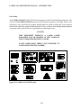

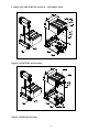


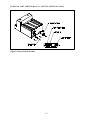
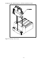
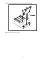

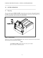
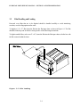
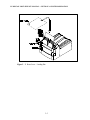
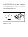
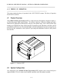
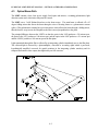
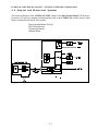
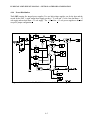
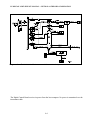

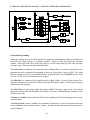

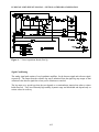
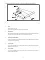
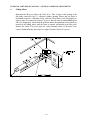
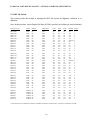


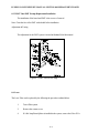
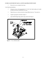
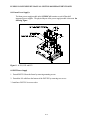

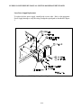
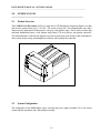
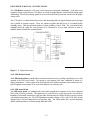
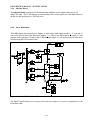
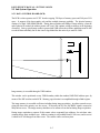
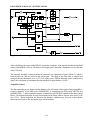
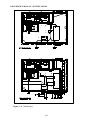
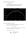
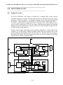
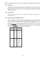
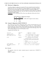


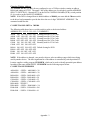


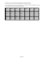


![MM12822 RvL 5-02 [German] Handheld](http://vs1.manualzilla.com/store/data/006788843_1-dd202c6a8f9102ffe4081d3aeba5a900-150x150.png)