1
Contents
Main Screen
Windows
Plot Screen
Signal Generator
Profile
Tuning
Failsafe
Miscellaneous
Pulse
Data Acquisition
Dacq View
Read/Write
Other Functions
Password
Communication Handling
How to Tune
Tuning Procedure
Contents
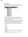
Main Screen
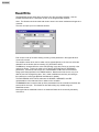
Normally, the first screen displayed upon running the ER3000 software is the main screen
(Note - If communication is not functioning another screen will display first. See
Communication Handling.) The main screen consists solely of a menu for accessing various
functions.
The "File" menu item contains three submenus: "Save Configuration", "Change
Configuration" and "Quit". "Save Configuration" will save the tuning parameters from the
controller to a file. "Change Configuration" will open a file containing previously saved tuning
parameters and download them to the controller. "Quit" is used to exit the program and
close any other windows which are open.
The "Node" item is used to change the node being communicated to. It has two submenus:
"Node Select" and "List Nodes". "Node Select" allows the user to enter a new node number
to communicate with. "List Nodes" produces a list box of all nodes which are connected to
the network; the user can then select one. See Communication Handling for more
information. Note that the node number with which the program is currently communicating
is shown in the Main Screen's title bar. This corresponds to the data in all windows.
The "Window" item is used to open various other screens. See specific sections for each
item:
Plot
Signal Generator
Profile
Tuning
Failsafe
Miscellaneous
Pulse
Data Acquisition
Dacq View
Read/Write
The "Refresh" item is used to read up all the parameters from the controller and refresh the
screens which are open. It is usually not necessary to do this unless parameters may have
changed locally.
The "Password" item will not be visible if the user does not have password authorization.
The "Help" item is used for accessing this online help system.
Contents
Context Sensitive Help
This help system is context sensitive. If the right mouse button is clicked on any open
screen the help system will be called for the appropriate topic.
Contents
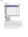
Plot Screen
The plot sceen is used to graphically display, in real-time, the current setpoint and feedback
from the selected controller. These values are updated every 100 milliseconds.
The main menu items are:
The "File" item has two subitems: "Print" to print a hardcopy of the current plot (with tuning
parameters) and "Quit" to close the plot screen.
The "Axis" item is used to set up the ranges for the horizontal and vertical axes. "Time"
corresponds to the time along the horizontal axis. Selecting "Minimum Vertical/Maximum
Vertical" allows for inputing the "Minimum" and "Maximum" ranges for the vertical axis. Also
"Full Scale" resets the vertical axis to the full range of the controller.
An alternate method of setting the vertical axis is via the mouse cursor. Left-clicking at two
points on the plot corresponding to the desired min and max of the plot will cause the vertical
axis to be rescaled. Double-left-clicking in any area of the plot will cause the vertical axis to
be reset to full scale. (Double-left-clicking a second time causes the plot to zoom out
further).
The "Labels" menu item causes the border and labels around the plot to be removed.
The "PlotStop" menu item (toggles to PlotStart) stops and starts the plot.
Contents
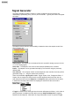
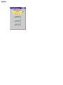
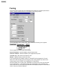
Signal Generator
The signal generator provides a means for creating a setpoint from the computer and
downloading it periodically (every 100 ms.) to the controller. Typically this screen will appear
as follows:
The setpoint source gives the user the ability to determine where the setpoint comes from.
The four options are:
Analog Input - The setpoint is to be obtained from the controller's analog input (4 to 20 mA
or 1 to 5 V analog signal).
Serial Port - The setpoint is to be sent via the serial port (RS485) to the controller.
Profile - The setpoint is to be generated internally by the controller using the previously
defined profile.
User Interface - The computer should not send setpoints to the controller since they will be
generated locally (i.e. - using the optional user interface).
There are five different signal types available: Toggle, Square, Sine, Triangle and Pulse. If
Square, Sine or triangle are chosen then the screen appears as above and the user can
enter the period of the wave and Setpoint 1 and Setpoint 2 (the peak values for the wave).
In addition the Run/stop button allows for stopping the waveform at the current value.
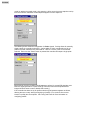
If Toggle is chosen as the wave type then the screen will appear as follows. In this case no
period parameter is available and the switch becomes Setpoint1/Setpoint2 for toggling
between the two setpoints. Note that if the "Signal Generator" screen is opened in toggle
Contents
mode (or switched to toggle mode) then setpoint 1 will be set to the current setpoint read up
from the controller unless the current setpoint happens to match setpoint 2.
The following screen shows the configuration for Pulse signals. Pulsing allows for manually
single pulsing the controller's solenoids. A pulse width of 100% corresponds to a 25 ms.
pulse on the inlet solenoid and a pulse width of -100% to a 25 ms. pulse on the exhaust
solenoid. Each time the "Pulse" button is pressed the controller will output a single pulse.
[Note however, that the controller will still attempt to perform it's normal PID algorithm even
when the signal generator is in pulse mode (to overcome this set the Proportional and
Integral min/max terms to zero to disable PID control).]
If the controller has been set up for profile mode the signal generator appears as follows,
allowing the user to stop, start (from beginning of profile) or run (continue from current
location in profile) the current profile. See Tuning and Profile for more information on
configuring profiles.
Contents
Contents
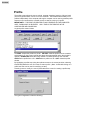
Profile
The profile screen allows the user to upload, generate, download, save (to a file) and read
(from a file) profiles which can be run on the controller. The ER3000 has the ability to run
profiles independently of the computer, although a computer can be used to generate profile
sequences and command the controller to stop or start the running of a profile.
IMPORTANT!!! - THE PROFILE CREATED IS ONLY PRESENT ON THE COMPUTER
UNTIL "DOWNLOAD" IS SELECTED. ONLY THEN IS THE PROFILE IN THE
CONTROLLER AND CAN BE RUN.
A typical profile screen follows.
The PRINT outputs the profile to a printer. UPLOAD reads the profile from the controller
and displays it on the screen (upload also takes place automatically when the window is
opened). DOWNLOAD writes the newly created or modified profile into the controller.
OPEN reads a profile from a file. SAVE writes a profile to a file. QUIT closes the profile
window.
By highlighting a profile step (using the up/down arrows or the mouse) and then selecting
insert/modify/delete the user can create a custom profile. (Note - double-left-clicking on a
profile item also can be used for modifying an item).
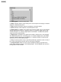
Choosing insert or modify, the user is presented with a screen for creating a profile step.
The types of segments include the following:
Contents
An "End" segment is used to end the profile.
A "Ramp" segment creates a ramp starting at the current setpoint and ramping to a desired
setpoint in a specified time period.
A "Step" segment changes the setpoint immediately to a desired setpoint.
A "Dwell" holds the current setpoint for a specified period of time.
A "Digital Output" is available on the optional user interface, UI3000, and on units equipped
with the digital output electronics. Specifying output 1 or 2 selects a digital output on the
UI3000 and output 3 or 4 selects a digital output on the ER3000. If available the specified
output is set to the specified state.
A "Digital Input" is available on the optional user interface, UI3000, and on units equipped
with digital/analog electronics. Specifying input 1 or 2 selects a digital input on the UI3000
and input 3 selects a digital input on the ER3000. If available the profile is halted until the
specified input is set to the specified state.
A "Loop" causes the profile to loop to a specified profile step a specified number of times (if
the number is specified as zero then the loop will continue indefinitely.
A "Change Variable" allows the user to set an embedded variable to a specified value.
Some of the variables are shown in the following diagram. See the ER3000 user manual for
the significance of each variable.
Contents
Contents
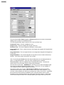
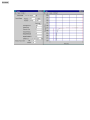
Tuning
The tuning screen contains the main parameters which affect the controller's performance.
See the Tuning Procedure section for more detail on the tuning process.
The first parameter is the control mode. When selected the following menu appears.
The four options for control mode are as follows:
Internal Feedback - Internal feedback (onboard sensor) used.
External Feedback - External feedback (user supplied sensor) used.
Cascade Loop - Both internal and external used.
Manual - Setpoint directly controls the valves.
If the controller goes into failsafe mode then "FAILSAFE" will be displayed for "Control
Mode" and if the controller goes into emergency stop mode (possible only with the user
interface option) then "ESTOP" will be displayed for Control Mode.
Note that, based on the control mode, parameters are shown for the Inner Loop and Outer
Loop as appropriate. In the following screen the Control Mode is set to Cascade Loop,
hence both Inner Loop and Outer Loop parameters are displayed (compare to screen above
which is set up for Internal Feedback).
Contents
The menu item labelled Simple (toggles to Advanced) reduces the number of parameters
displayed and is useful for inexperienced users.
The following parameters apply to both the Inner Loop and Outer Loop:
Proportional Term - This term multiplies the error.
Integral Term - This term multiplies the integral of the error.
Derivative Term - This term multiplies the derivative of the feedback.
Integral Minimum - This is a lower limit set on the integral (the integrator will integrate down
to this value.
Integral Maximum - This is an upper limit set on the integral (the integrator will integrate up
to this value.
Integral Deadband - This causes integration to stop when the error is within this band (in
percent). If this value is set to zero then it has no effect.
Note - By choosing the Format menu item the preceding items can be displayed either as
gains or as Bands/Reset/Rate. Gains are simply multiplying factors whereas
Bands/Reset/Rate is the more traditional way of specifying PID values. Thus the user
should choose one or the other format to enter tuning parameters.
The next value on the screen - ExtFBSource is the source for the external feedback signal.
The choices are External Feedback and Extra Input 1. Extra Input 1 is only available on
units equipped with the additional digital/analog inputs.
The next two values on the screen - Minimum Pulse Width for the inlet and exhaust
solenoids are the minimum values which are written to the pulse width modulators. They
can have a value between zero and 50 (50 corresponds to a duty cycle of 20%). Essentially,
these values are used to define the deadband of the output and prevent noise or small
fluctuations in the controlled pressure from causing the valves from opening. Small values
can be used to keep the valves from constantly sputtering and large values to prevent the
Contents
output pressure from varying much before taking action.
The following parameters pertain to the Sensor:
Minimum Range - The value corresponding to the minimum for the sensor. In the case of an
external 4 to 20 mA transducer, this is the value which corresponds to 4 mA.
Maximum Range - The value corresponding to the maximum for the sensor. In the case of
an external 4 to 20 mA transducer, this is the value which corresponds to 20 mA.
Units - Up to four characters which the user wishes to use to refer to the reading. This string
is applied to the plot screen and to the optional user interface.
Note - If the user wanted to set up a system in internal feedback mode to display bar,
instead of PSI, he/she would set units = "BAR", minimum range = "0", maximum range "6.8947" (since 100 psi = 6.8947 bar).
Contents
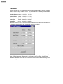
Failsafe
Failsafe checking is not usually used, however, it provides the ability to shut the controller
down if an out of range condition occurs. Any combination of the following five parameters
can be checked:
Analog Setpoint (range : -12.12% to 111.97%)
Internal Sensor (range : -12.12% to 111.97%)
External Sensor (range : -12.12% to 111.97%)
Inner Error
(range : -124.12% to 124.09%)
Outer Error
(range : -124.12% to 124.09%)
When the minimum value is set to the minimum value above and the maximum value is set
to the maximum value above then the failsafe checking is disabled.
When any value is selected (via a mouse click) the following dialog box is displayed. The
"Out of Range" message is displayed if a value entered is not allowed. Selecting the
"Disable" button will set the value to it's extreme and thus disable failsafe checking for the
corresponding limit.
Contents
The final item on the failsafe screen, Failsafe Condition allows selecting one of the
following conditions to be established should the failsafe condition exist.
Normally, "Inlet Closed/Exhaust Open" should be selected so that the controller vents to
atmosphere if a failsafe limit is exceeded.
The Disable All button can be used to completely shut off the failsafe feature (most users
will not need to use this feature).
Contents
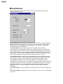
Miscellaneous
The miscellaneous screen contains a collection of parameters which don't fall into the
category of any other screen.
The calibration parameters allow for fine adjustment of the controller. From the factory the
span is set to 100% and the zero to 0%. However, the user may find it useful to adjust
these parameters to compensate for external transducers (for example - overstressed
transducers which need recalibration).
The "Node Number" can be input to change the node number of the unit being
communicated with. Note that this is different from changing node from the main screen.
When changing node from the main screen, the program merely attempts to communicate
with a different controller. When changing node from the Miscellaneous screen, the node
number of the current controller is reprogrammed (the main screen node is also updated so
that the windows program continues to communicate with the same controller).
The "Feedback Filter" is a switch which enables/disables filtering of the feedback signal
internally in the controller. Note that the signal used by the control algorithm is not filtered.
This is useful for cleaning up noisy transducer signals for display on the plot screen.
The "Solenoid" parameter can be set to either "NORMAL" or "REVERSE". Reverse
corresponds to reversing the action so that instead of opening the inlet solenoid, the exhaust
solenoid is opened and vice versa. An example use for this feature would be if an external
temperature transducer is used as feedback and the controller is regulating cooling air for
temperature control. Thus, it is necessary to increase the flow in order to reduce the
temperature.
The "Serial Number" is a factory programmed parameter and should not be changed by the
user.
The "Version Number" indicates the version of the software in the unit. It is not changeable
by the user.
Contents
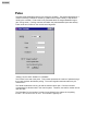
Pulse
The pulse mode parameters allow for fine tuning the controller. The pulse mode allows for a
means of reducing oscillations caused by systems which respond slowly to adjustments
made by the controller. Pulse mode is only activated within the integral deadband region
(see Tuning screen). Pulsing continues until within the pulse deadband (see value below).
Pulse mode has no effect on the normal control algorithm.
"Pulsing" can be either "Enabled" or "Disabled".
The "Period" is the rate of the pulse. This number represents the number of passes through
the control algorithm task before pulsing. The control algorithm task executes every 25
milliseconds.
The "Width" determines how long to hold the solenoid valve open. Part of this number
compensates for allowed noise in the control system. Therefore, too small a number will not
open the valve.
The "Deadband" is the number of counts of error allowed in the system for the pulsing
function. One count of error is .03%. This number is typically 0-3.
Contents
Data Acquisition
The Data Acquisition screen provides a means of saving setpoint and feedback data to a
disk file. The data can then be viewed using the Dacq View functions.The sample rate can
be any multiple of .100 seconds. The user specifies the filename for the data (if it already
exists a message is displayed warning the user). The number of samples can also be
specified. Or by pressing the start button followed by later pressing the stop button (the
single button toggles between the two) data can be collected under manual control.
An optional file header can be written to the start of the file which includes the date and time
and a user specified comment. Delimiters between data (data includes the time, with a
resolution of .001 seconds, the setpoint and the feedback) can be specified as spaces, tabs
or commas.
Contents
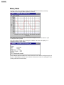
Dacq View
The Dacq View screen provides a means of viewing data which has been previously
collected to a file using the Data Acquisition functions.
After loading the screen the user must choose "File/Open" to load in a data file. Up to
10,000 points will be plotted.
If the file includes a header then choosing the "Header" menu item will display it in a
separate window as shown below.
Once a data file has been loaded, the zoom menu item can be chosen to enlarge a region of
the plot. Alternatively the mouse can be used to choose two corners of a rectangle to zoom
(clicking with the left mouse button).
Contents
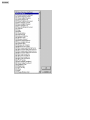
Read/Write
The Read/Write screen allows direct access to all of the controller's variables. See the
ER3000 User Manual for a description of each of the programmable variables.
Note - This function should be used with caution since it can cause inadvertent changes to to
controller.
The user can open up to four read/write screens.
Each screen is set up for either reading or writing via the parameter in the upper left hand
corner of the screen.
The variable number to be read or written can be entered directly or the user can select the
desired ID via the list box (the box showing "ID_SETPOINT" above).
The PSI entry corresponds to the value read (reading occurs about once per second) or the
value to be written. This box is visible only for the ID_SETPOINT and ID_FEEDBACK
parameters. It scales the value read, as in "RAW ER3000 16-BIT DATA" to the Sensor
Range (and Units) specified in the TUNING window. Note that the write occurs only once
after the user has changed the value. Also, certain variables are read-only and writing to
them will have no effect (see ER3000 User Manual for details).
The RAW ER3000 16-BIT DATA entries are the SIGNED, UNSIGNED, and HEX
representations of the data read from or written to the controller.
The Refresh! button is used to read up all the parameters from the controller and refresh the
screens which are open. This should be done after writing any variable using the
Read/Write screen.
Note again that the read/write screen is an advanced feature and not normally needed by
most users.
Contents
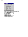
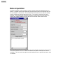
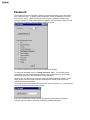
Password
The windows tune program provides a means for password protecting each of the screens
from unauthorized use. To enable password protection choose the password menu item
from the main screen. (Note- this menu item only appears if password protection was
previously disabled or if the user has previously logged in with a password.) After choosing
the main menu password item the following screen will appear.
To enable the password the first item must be selected to "Enable".
To change the password press the "Change Password" button. The user will then be
prompted to enter the old password (the software uses the word "tescom" as the initial
password) and then enter the new password (with verification).
Next the user can select any of the screens which should be password protected. In the
screen shown above the Signal Generator, Read/Write and Profile screens have been
selected for password protection.
The password will not take effect until the next time that the program is run. At that point the
user will be presented with the following screen:
If the correct password is entered then the program will run the same as if password
protection was not enabled. Otherwise the following message will appear.
Contents
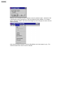
Selecting "Yes" will allow the user to attempt to enter the password again. Otherwise if "No"
is selected then the program will be run with the selected screens disabled. For example,
with the selections shown in the screen at the beginning of this help topic the main menu will
appear as follows:
Notice that the Signal Generator, Profile and Read/Write menu items appear in grey. This
means that these menu items cannot be selected.
Contents
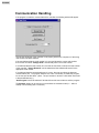
Communication Handling
If the program is unable to communicate with a controller the following window will appear:
This window will appear if the controller is not properly wired to the computer or if the wrong
node number has been selected.
If the user believes that the node number is in error and knows the correct node number
then he/she can select "Change Node" and manually enter a new node number.
If it is believed that the node number is in error but the user does not know the node number
of the controller, "Search Network" can be selected and the software will search for the
appropriate node number.
If it is believed that the communication port is in error, the user can select the alternate
communication port. The program will then exit, and it is necessary to restart the program
for the new port to take effect. (Note - The port number is stored in a file called "tescom.ini"
in the windows directory.)
"Quit Program" should be selected if all else fails and the user wishes to exit the program.
The Simulate button can be used to run the software in simulation mode (i.e. - without
actually communicating with a controller).
Contents
Tuning Procedure
This section will cover an example tuning procedure.
To begin, it should be realized that the tuning of PID controllers is learned with experience.
However, the following basic concepts should allow the inexperienced user to tune their
loops sufficiently well for the majority of applications.
There are some features of the ER3000 which are unique compared to other PID controllers
and allow the system to be optimized. In particular, the use of four different modes of
operation, the setting of minimum values for inlet and exhaust valves (deadband adjust) and
the setting of maximum and minimum values for the integral sum allow for greater flexibility.
To begin, three windows should be opened :
. Tuning (Advanced!).
. Signal Generator.
. Plot.
Each system has unique requirements, and since tuning will always be a compromise
between various tradeoffs, it is necessary to decide what are the most important parameters
for the given application. Typical goals include the following:
.
.
.
.
Maximize speed of response.
Minimize peak overshoot.
Minimize DC offset.
Minimize settling time.
In addition, the region of operation will affect how the unit is tuned. This application will be
operating primarily in the 0 to 2500 psi region. Thus tuning should be performed over this
entire range. However, the final setup should be tested in intermediate pressure ranges as
well, to verify maximum performance throughout the system's range.
In the Tuning Window, make sure the Control Mode is set to External Feedback and the
Sensor Range Minimum and Maximum are 0 and 2500 respectively. The ER3000 is
shipped with outer loop PID parameters that have been established at the factory to work
well with the regulator in that system, however, in this example we will begin tuning by
setting the parameters as follows:
•
•
•
•
•
Proportional: 200.
Integral : 0.
Derivative : 0.
Integral Minimum : 0.
Integral Maximum : 0.
(Note - For cascade control it is best to set the Integral Minimum = 0 and Integral Maximum
= 32767. This is because it is necessary to maintain a positive pressure on the dome of the
regulator to maintain output pressure from the system.)
In the Signal Generator, set 'Setpoint 1' & 'Setpoint 2' to 625 and 1875, which is 25% and
75%. Make sure that the plot screen is set up to show the entire tuning range. For example,
with the above setpoints, the display should be set up for 0 to 2500.
Since tuning is generally done using step changes, set up 'Wave Type' for option 'TOGGLE'.
Now click on the "Setpoint 1/Setpoint 2" in the Signal Generator to toggle between the two
setpoints.
Contents
With the proportional term set to 200, the response will be relatively slow. The first step in
tuning is to see how far the proportional term can be increased. In general, increasing the
proportional term will decrease the response time (i.e. - make the response wave more
square), however a point will be reached at which the effect becomes detrimental. That is,
too much proportional term will result in overshoot and possibly ringing of the response.
Also, it should be noted that the effect of the tuning parameters (PID) tend to be logarithmic.
Thus a possible sequence of values to try for the proportional term might be 200, 400, 800,
1600, until ringing and/or overshoot occurs and then narrow down to an optimal value, one
which gives just a slight amount of overshoot and ringing.
Next the derivative term should be increased so as to reduce the overshoot and ringing in
the system. However, too much derivative term may result in a noisy output.
Once the optimal proportional and derivative terms are found, the integral term should be
adjusted. The integral term has the effect of eliminating DC offsets, however too much
integral will lead to instability (overshoot and ringing). Again the effect is logarithmic so
values such as 10, 20, 50 , 100, 200, 500, 1000 ... can be tried until an optimal value is
obtained.
At this point it should be noted that the ER3000 provides a unique integral limiting feature
('Minimum Outer Integral' and 'Maximum Outer Integral'). This allows for using large integral
terms without creating excessive overshoot. It should be realized that the integral sum is
what holds the valves open even when there is zero error. For closed-ended systems the
minimum and maximum integrals can be very small. However, for systems requiring flow it
is necessary to keep these values higher. To determine how small they can be made
(remember - smaller is better as long as proper flow is maintained) the setpoint should be
set to the maximum level and the minimum and maximum reduced until flow is no longer
maintained, then slightly increase these values. Often, for closed ended systems a value of
one or two is sufficient.
After performing the steps mentioned above, tuning can often be improved by iterating
between the various parameters. Although performing basic tuning can be simple, learning
to fully optimize the tuning requires experience, so experiment!
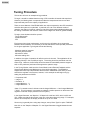
The following is an example sequence of tuning steps. First a very undertuned response is
shown (note size of proportional term).
Contents
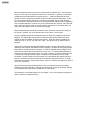
Next the proportional term is increased, however, overshoot and ringing results:
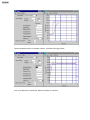
Now, some Derivative is introduced. Note the decrease in overshoot.
Contents
However, if we zoom in on the horizontal axis between 1750 and 2000 psi, we notice that a
small offset remains.
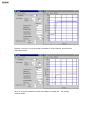
What can be done to eliminate the offset is the addition of integral term. The resulting
response follows:
Contents