1
Multiplexing Transceiver System
FS1001M
User Manual
Application Firmware Version 2.1
Copyright
© Copyright 2010 Destron Fearing Corporation. All Rights Reserved. This manual contains valuable
proprietary information. It should not be published, copied, or communicated to any person without prior
authorization from Destron Fearing.
Trademarks
Destron Fearing is a registered trademark of Destron Fearing Corporation. Microsoft and Windows are
registered trademarks of Microsoft Corporation. All other trademarks, tradenames, or images mentioned
herein belong to their respective owners.
Document History
Release Date
Doc Version
Firmware Version
Comments
July 2010
B
2.1
Updated for new firmware version release.
FS1001M User Manual
Page II
Destron Fearing Corporation
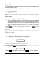
TABLE OF CONTENTS
PRODUCT DESCRIPTION ........................................................................................................................... 1
Functional Description...................................................................................................................... 1
READER OVERVIEW ................................................................................................................................... 3
LCD Display and LED Indicators ..................................................................................................... 3
Activity indicator .................................................................................................................. 4
Reader status indicator ....................................................................................................... 4
Alarm indicator .................................................................................................................... 4
Buffer mode indicator .......................................................................................................... 5
Unique mode indicator ........................................................................................................ 5
Tag ID indicator ................................................................................................................... 5
Keypad ............................................................................................................................................. 5
Reset key ............................................................................................................................ 6
Read key ............................................................................................................................. 6
Menu, Escape and Enter keys ............................................................................................ 6
Audible Indicator .............................................................................................................................. 6
Serial Communication Port .............................................................................................................. 6
Reader Components ........................................................................................................................ 7
SCANNING FOR TAGS (Scan and Stby modes) ......................................................................................... 8
Manual Scanning ............................................................................................................................. 8
Remote Scanning ............................................................................................................................. 8
Tag ID Detection .............................................................................................................................. 8
Reader status ................................................................................................................................... 9
Antenna Display .................................................................................................................. 9
Alarm List ............................................................................................................................ 9
Records Count .................................................................................................................. 10
Date and Time................................................................................................................... 10
CONFIGURING THE READER .................................................................................................................. 11
Keypad Navigation and Operation ................................................................................................. 12
Reader Menu ................................................................................................................................. 12
Reader unique................................................................................................................... 13
Reader unique delay ......................................................................................................... 13
Reader ID in hex ............................................................................................................... 14
Reader buzzer ................................................................................................................... 14
Reset parameters.............................................................................................................. 15
Buffer Menu .................................................................................................................................... 15
Buffer active ...................................................................................................................... 16
Buffer download ................................................................................................................ 16
Buffer erase....................................................................................................................... 17
Buffer test tag .................................................................................................................... 17
Local Menu ..................................................................................................................................... 17
Send tag setting ................................................................................................................ 18
Antenna Menu ................................................................................................................................ 18
FS1001M User Manual
Page III
Destron Fearing Corporation
Antenna Sequence............................................................................................................ 19
Antenna 1 – 6 Tuned Ph ................................................................................................... 19
Scan time .......................................................................................................................... 20
Sleep time ......................................................................................................................... 20
Diagnostic Menu ............................................................................................................................ 21
System temperature .......................................................................................................... 21
Exciter ............................................................................................................................... 21
Current gain % .................................................................................................................. 22
Alarm mA .......................................................................................................................... 23
Virtual test tag ................................................................................................................... 23
TstTAG delay .................................................................................................................... 24
Report delay ...................................................................................................................... 25
Noise delay ....................................................................................................................... 29
Send status ....................................................................................................................... 30
Noise gain % ..................................................................................................................... 30
Noise Alm .......................................................................................................................... 30
SERIAL COMMUNCATION PORT OPERATION ....................................................................................... 32
Hardware Description ..................................................................................................................... 32
Configuration .................................................................................................................................. 32
Command/response Messages ..................................................................................................... 32
General Format .............................................................................................................................. 32
Command List ................................................................................................................................ 33
Help (H or ?) ...................................................................................................................... 33
Antenna switching sequence (AS) .................................................................................... 33
Antenna scanning time (AT) ............................................................................................. 34
Buffer active (BA) .............................................................................................................. 35
Buffer count (BC) .............................................................................................................. 35
Buffer download (BD) ........................................................................................................ 35
Buffer erase (BE) .............................................................................................................. 35
Low current alarm threshold (DA) ..................................................................................... 36
Current measurement gain (DG) ...................................................................................... 36
Status report delay (DRD) ................................................................................................. 36
Status report send (DRS) .................................................................................................. 36
Store test tag code (DS) ................................................................................................... 37
Test tag on/off/single shot (DT)......................................................................................... 37
Test tag delay (DTD) ......................................................................................................... 37
Send tag codes to COM1 (LT) .......................................................................................... 38
Manual tuning mode (MT) ................................................................................................. 38
Noise measurement gain (NG) ......................................................................................... 40
High noise alarm threshold (NT) ....................................................................................... 40
Noise report delay (NRD) .................................................................................................. 41
Noise report send (NRS) ................................................................................................... 41
Reader active (RA)............................................................................................................ 41
Reader buzzer active (RB) ................................................................................................ 41
Reader Hex ID (RI) ........................................................................................................... 42
Reset parameters to default (RP) ..................................................................................... 42
FS1001M User Manual
Page IV
Destron Fearing Corporation
Reader unique on/off (RU) ................................................................................................ 42
Reader unique delay (RUD) .............................................................................................. 42
Antenna sleep mode delay (SM) ....................................................................................... 43
Display current date and time (TC) ................................................................................... 43
Test reader efficiency (TE) ................................................................................................ 43
Reader date (TD) .............................................................................................................. 43
Reader time (TH) .............................................................................................................. 44
Test tag level (TL) ............................................................................................................. 44
SELF TESTS AND DIAGNOSTICS ............................................................................................................ 45
Power-up Diagnostics .................................................................................................................... 45
Startup Sequence ............................................................................................................. 45
Flash EEPROM Memory Test ........................................................................................... 46
RAM Memory Test ............................................................................................................ 46
Power Supply Verification ................................................................................................. 46
Back-up Lithium Battery Verification ................................................................................. 46
Periodic Self-tests .......................................................................................................................... 47
Virtual test tag detection ................................................................................................... 47
System parameter monitoring ........................................................................................... 47
Critical antenna current protection .................................................................................... 47
Elapsed Shutdown Time (ESDT) ...................................................................................... 47
Antenna switching relays usage counter .......................................................................... 48
Alarm Messages ............................................................................................................................ 48
MAINTENANCE .......................................................................................................................................... 49
Back-up Lithium Battery Replacement ........................................................................................... 49
System Tuning Procedure.............................................................................................................. 49
Tools Required .................................................................................................................. 49
Procedure .......................................................................................................................... 49
Reader Firmware Update ............................................................................................................... 52
Requirements .................................................................................................................... 52
VBFlash program installation ............................................................................................ 52
VBFlash program operation .............................................................................................. 52
Reader firmware update procedure .................................................................................. 54
Cleaning Instructions...................................................................................................................... 57
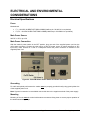
ELECTRICAL AND ENVIRONMENTAL CONSIDERATIONS.................................................................... 58
Electrical Specifications ................................................................................................................. 58
Fuses ................................................................................................................................ 58
Main Power Source ........................................................................................................... 58
Main Power Connection .................................................................................................... 58
Grounding ......................................................................................................................... 58
Mounting ........................................................................................................................... 58
Environmental Recommendations ................................................................................................. 59
Surroundings ..................................................................................................................... 59
Altitude .............................................................................................................................. 59
Temperature range ........................................................................................................... 59
Relative Humidity .............................................................................................................. 59
Pollution ............................................................................................................................ 59
FS1001M User Manual
Page V
Destron Fearing Corporation
This page intentionally left blank.
FS1001M User Manual
Page VI
Destron Fearing Corporation
PRODUCT DESCRIPTION
The FS1001M (Multiplexer) RFID reader is a high performance auto tuning unit specifically designed for
installations requiring up to 6 antennas where the environmental conditions necessitate the need for auto
tuning, where antennas must be placed in close proximity to one another, or where the power budget is
limited.
Features:
Full-time auto tuning to compensate for changes in the antenna environment.
Support for up to six antennas.
Remote and local interface for setup, maintenance, status monitoring, and data logging.
DC power input configuration.
Interface:
Two lines by 16 characters LCD display with backlight.
Five-key keypad that allows local operation and reader configuration.
EIA 232 serial communication port, female DB-9 connector.
Connections for six antennas.
Firmware:
Field-updateable firmware.
Configurable non-volatile set-up parameters.
Data logging memory for up to 5,350 tags with reader ID,
antenna number, and date and time stamp for each tag.
Data logging memory for up to 146 System Status Reports.
Data logging of test tag activations.
Functional Description
The FS1001M is designed to drive up to six antennas and provide
independent auto tuning for each antenna. It multiplexes or switches
between the antennas in a user selectable sequence. Since only one
antenna is activated at a time the antennas can be placed in any
location and orientation without interfering with one another. The
antenna switching also has the added benefit of supporting up to six
antennas using approximately the same power as a single Stationary
FS1001A reader.
When the unit switches to an antenna it automatically retunes to that
particular antenna and makes necessary tuning adjustments due to
environmental changes such as water level, temperature, etc. The
unit then looks for the presence of a PIT tag in the antenna field. If
no tag is present the unit switches to the next antenna, set by a
switching sequence, and repeats this process. If a tag is present the
unit will stay at the antenna until the tag is successfully read or the
allotted scanning time expires, whichever comes first. After the last
antenna in the switching sequence is reached the cycle is repeated.
The default timing of antenna switching process is 30ms for
determining the presence of a tag, and 100ms (user-defined
parameter, up to 1 second) to read a tag.
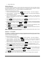
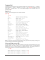
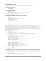
FS1001M User Manual
Page 1
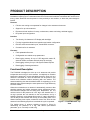
Figure 1: FS1001M Reader Top
View
Destron Fearing Corporation
As an example, an installation with four antennas and an antenna switching sequence of 1-2-3-4 would
take 120ms (4 x 30ms) to cycle through all four antennas if no tag was detected on any of the four
antennas. The system would check for the presence of a tag at each antenna every 90ms (3 x 30ms).
When a tag enters the field of one of the antennas, if the antenna scan time is 100ms, the antenna cycle
time would increase to a maximum of 220ms. This is explained in greater detail in subsequent sections.
Note: If necessary, the default switching time value of 30ms can be changed to 20, 25, or 44ms by
reprogramming the reader with the appropriate application firmware (see Reader Firmware Update).
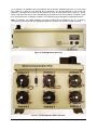
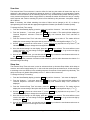
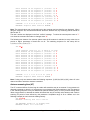
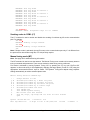
Figure 2: FS1001M Reader Side View
Figure 3: FS1001M Reader Bottom End View
FS1001M User Manual
Page 2
Destron Fearing Corporation
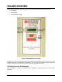
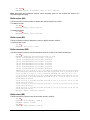
READER OVERVIEW
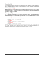
The FS1001M front panel is illustrated in the next figure, showing the main interface components:
LCD display
LED indicators
Context sensitive keypad
Figure 4: FS1001M Reader Front Panel
In addition to the LCD and Keypad interface the FS1001M has an audible indicator (beeper) and a serial
communication port for connecting to a computer. The FS1001M menu structure is quite deep and
complex. Users are required to use a computer for initial setup and antenna tuning.
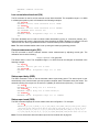
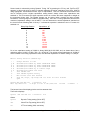
LCD Display and LED Indicators
The LCD display is 2 lines by 16 characters with a backlight. It displays tag IDs and reader status
information.
FS1001M User Manual
Page 3
Destron Fearing Corporation
Power Indicator
Unique Active
Activity Indicator Buffer Active
Status
Alarm
TAG Read
Antenna
TAG ID
Figure 5: FS1001M Reader LCD Display with LED Indicators
The top ON LED located left of the display is the reader power indicator. The bottom READ LED flashes
each time a tag is read: this LED is turned on each time a tag message is decoded successfully,
regardless of the Unique Mode setting.
Activity indicator
On the first line of the LCD, the unit features an animated antenna activity indicator that changes shape
each time a new signal data buffer is acquired from the antenna.
Figure 6: Activity Indicator Animation
Reader status indicator
The next display field is used to display the reader activity and the tag search result. The unit can
display:
The reader is inactive (standby mode), waiting for a user command through the
keypad or through the communication port.
The reader is active (scan mode) and searching for tags.
The unit has found a new tag. The tag number found by the unit is different from the
previous one found by the unit.
The unit has found a tag but its number is the same as the last one detected by the
unit.
Alarm indicator
The next 3-character zone is used to indicate the presence of an alarm. See page 47 for a list of all
possible alarms and their descriptions.
FS1001M User Manual
Page 4
Destron Fearing Corporation
The alarm messages are also sent to the communication port as they occur. A list of alarms that have
occurred and are still active can be displayed on the LCD using the system summary feature, available by
pressing the Enter key from the main display. A complete list of occurred alarms is also available at the
end of the Status Report sent to the communication port.
Buffer mode indicator
Letter “B” (Buffer) on the right side of the first LCD line indicates that the Buffer mode is enabled. When
enabled, the Buffer option allows tag IDs to be stored in the reader memory as they are read along with
the reader ID, antenna number, and date and time of detection. This information is stored in a memory file
that has a capacity of 5,350 tag codes. In the case of a power outage back-up lithium battery will protect
the memory file contents. Each tag ID in the memory is protected by a CRC (cyclic redundancy check) in
order to avoid invalid information being retrieved by the computer. When the memory file is full, the oldest
tag ID is erased in order to store the new tag ID found. The memory file contents can be downloaded to a
computer and erased using either the front panel (Buffer menu) or the communication port connection.
Unique mode indicator
Letter “U” (Unique) on the right side of the first LCD line indicates that the Unique mode is activated. The
Unique mode defines the reaction of the reader when the same tag is read several times sequentially on
the same antenna (Unique mode is antenna-specific). When the Unique mode is off, the tag will be
reported each time it is read. When the Unique mode is on, the tag ID will be reported only once for each
antenna it is detected on until either five other different tags are detected on those antennas or the
Unique Delay times out (if the mode set to Delay). See Unique Mode on page 13 for additional
information.
Tag ID indicator
The second line of the LCD displays detected tag ID in hexadecimal format and an antenna number
where this tag was detected in the following pattern: antenna number followed by a space then
manufacturer ID or country code followed by a universal identification code all in capital letters.
Figure 7: FS1001M Reader Tag ID Display
Keypad
The unit is equipped with a 5 keys context sensitive keypad, which means that the use of the keypad is
adapted to the information being displayed on the LCD (see Figure 9).
READ
RESET
MENU ESCAPE ENTER
Figure 8: FS1001M Reader Keypad
FS1001M User Manual
Page 5
Destron Fearing Corporation
Reset key
The unit can be restarted using the RESET key. When resetting, the unit performs self-diagnostics and
starts scanning for tags. Please refer to the “Power-up/reset sequence” section for more details.
Read key
The READ key is used to activate/deactivate the scanning of tags. Pushing READ toggles the unit
between the scanning mode and the standby mode.
Menu, Escape and Enter keys
The MENU , ESCAPE and ENTER keys are context sensitive navigation keys used to access:
The reader overview that provides detailed information about the reader operation.
The file management utility that allows creation, deletion and downloading of memory file to a
computer using the serial communication port.
The configuration menu.
Key usage is described in the next chapter.
Audible Indicator
The audible indicator (beeper) is located on reader’s CPU board. The audible indicator provides:
Tactile feedback for the keypad.
Indication that a tag has been read (short beep).
Indication that an abnormal condition (alarm) has been detected (2 short beeps).
Serial Communication Port
All functions and information available through the front panel is also available through the serial
communication port and some of the operations such as antenna setup and tuning can be only performed
through the communication port.
This port is an EIA 232 communication interface with a female 9-pin DIN connector. The communication
parameters are fixed at 57,600 baud, no parity, eight bits, one stop bit, (57600, N, 8, 1) with no flow
control. Standard straight through communication cable is required (DB-9 Female/Male connectors,
straight through, NOT null modem).
FS1001M User Manual
Page 6
Destron Fearing Corporation
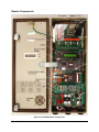
Reader Components
Figure 9: FS1001M Reader Components
FS1001M User Manual
Page 7
Destron Fearing Corporation
SCANNING FOR TAGS (Scan and Stby modes)
The tag scanning process can be started and stopped in different ways:
Manually using the READ key
Remotely using the communication port command
Note: The reader starts up in the Scan mode after a reset or power up.
Manual Scanning
Manual scanning is done through the FS1001M front-panel keypad using the READ key:
In the Standby mode, momentarily push the READ key to Scan for tags.
During the tag Scan, momentarily push the READ key to return to the Standby mode.
Remote Scanning
The RA command can be used to start and stop the scanning through the communication port. RA1 will
start the Scan mode and RA0 will return the reader to the Standby mode. RAR will reset the reader.
Please refer to the Reader active (RA) section for more details.
Tag ID Detection
When scanning, the following annunciation process occurs upon detection of a valid tag ID:
1. The antenna number and tag ID is displayed on the second line of the LCD (antenna number followed
by a space then manufacturer ID followed by universal code all in hexadecimal format). If the tag
number is different from the preceding tag found, the first line will briefly display "FOUND". If the
number is the same as the preceding tag, the display will briefly show "SAME".
2. The READ LED indicator (left of the display) is turned ON each time a valid tag message is detected.
Therefore, the LED will flash until the tag is removed from the antenna detection range.
3. The beeper is activated briefly if it is enabled (see Reader Buzzer, page 14). This option can be
turned on or off through the keypad menu or the communication port.
4. The tag ID message is sent to the communication port if "Send tag" is enabled. This option can be
turned on or off through the keypad menu or the communication port.
5. If the Buffer mode is selected, the tag ID is stored in the memory file along with antenna ID and the
current date and time.
Note: The above sequence is somewhat different when UNIQUE or UNIQUE DELAY is enabled.
See the UNIQUE and UNIQUE DELAY command descriptions on page 13 for details.
FS1001M User Manual
Page 8
Destron Fearing Corporation
Reader status
The system status information available through the front panel allows a user to examine detailed reader
status through the display, including:
Antenna current, relative antenna signal phase and noise signal level.
Complete list of occurred alarms.
Number of tag codes stored.
Date and Time.
A full system status report is available through the communication port; see Status Report on page 25 for
details.
Antenna Display
The six “Antenna #” displays show the following information:
The first value is the antenna current in Amperes peak-to-peak.
The next or middle value is the relative phase. This is the difference between the actual antenna
signal phase and the target phase for that antenna. The system uses this phase difference to
adjust the tuning capacitance of the antenna. This is discussed in greater detail on pages 18 and
38.
The last value is average noise signal level seen on the antenna. See pages 29 and 38 for more
details.
Pressing the ENTER key will show the next Antenna Display or the Alarm List, or ESCAPE will return to
the main display.
Alarm List
The Alarm List allows a user to see detailed description of all alarms that have occurred and are still
active.
When new alarm is detected:
The reader beeps twice.
A detailed alarm message is sent to the communication port.
An abbreviated alarm message is displayed on the LCD main screen.
If no alarms are active, the following message is displayed on the Alarm List screen:
No alarms
A detailed list of alarms and their descriptions can be found on page 47.
A down arrow () is displayed on the right corner side of the display when more than one alarm exists. A
user must then press the MENU key to see the remaining alarms.
Test Tag Failed
Pressing the ENTER key again will show the Records Count, or ESCAPE will return to the main display.
FS1001M User Manual
Page 9
Destron Fearing Corporation
Records Count
The Records Count displays the number of tag IDs presently stored in the buffer. The buffer can store a
maximum of 5,350 tag IDs with reader ID, antenna ID and date and time stamps.
Pressing the ENTER key again will show the Date and Time, or ESCAPE will return to the main display.
Date and Time
The Date and Time displays current system clock setting used to stamp tag IDs as they are detected.
At this point, pressing the MENU , ENTER or ESCAPE keys will return to the main display.
FS1001M User Manual
Page 10
Destron Fearing Corporation
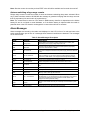
CONFIGURING THE READER
One of the exclusive features of the FS1001M reader is its ability to be adapted to several types of
operations and applications. The FS1001M operation can be tailored to a customer’s needs using the
configuration setup through the front panel keypad and display. It should be noted that any change can
also be made through the communication port using the appropriate command.
The FS1001M reader has five primary menus and several sub-menus for selecting operating options. The
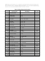
following table shows the menu structure.
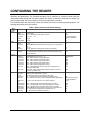
Table 1: Menu Structure and Default Settings
Main
menu
Reader
Sub-menu
Available settings
Default
Unique
Unique Delay
ID in HEX
On, Off, Delay
0001 – 1440 (unique mode delay in minutes)
00, 10, 20, … , F0
On
0030
F0 (can be set during
firmware installation)
On
No
Buzzer
Reset parms
On, Off
No, Yes
Active
Download
On, Off
Pressing Enter will download the buffer memory to the communication
port
No, Yes
On, Off (determines if test tag IDs are stored in the buffer)
On
Send tag
No, Yes (determines if tag IDs are sent to the communication port as
they are detected)
Yes
Sequence
1 Tuned Ph
2 Tuned Ph
3 Tuned Ph
4 Tuned Ph
5 Tuned Ph
6 Tuned Ph
Scan Time
XXXXXXXXXXXX (where X is 1 – 6)
0000 – 9999 (antenna 1 target phase value)
0000 – 9999 (antenna 2 target phase value)
0000 – 9999 (antenna 3 target phase value)
0000 – 9999 (antenna 4 target phase value)
0000 – 9999 (antenna 5 target phase value)
0000 – 9999 (antenna 6 target phase value)
0040 – 1000 (added antenna active time when a tag presence is
detected in milliseconds)
0000, 0002 – 9999 (antenna idle time before switching to the next
antenna in 10 milliseconds)
123456000000
0650
0650
0650
0650
0650
0650
0100
Buffer
Erase
Test Tag
No
On
Local
Antenna
Sleep Time
0000
Diag
Sys Temp
Exciter
Curr gain %
Alarm mA
Displays system temperature in Celsius
Displays exciter power supply voltage (+VE) in volts
001 – 200 (antenna current measurement calibration gain %)
0001 – 9999 mA (low antenna current alarm threshold in milliamperes)
Virtual Test
tag
TstTAG delay
Report delay
Noise delay
Send status
Noise gain %
Noise Alm
On, Off, S-S (for all antennas or for a specific antenna)
FS1001M User Manual
0000 – 1440 (automatic test tag activation delay in minutes)
0000 – 1440 (automatic status report sending delay in minutes)
0000 – 1440 (automatic noise report sending delay in minutes)
Pressing Enter will send the status report to the communication port
001 – 200 (noise level measurement calibration gain %)
01 – 99 (high noise level alarm threshold %)
Page 11
110
1000 (can be set during
firmware installation)
Off All
0060
0240
0000
100
30
Destron Fearing Corporation
Keypad Navigation and Operation
The reader contains four different keys that can be used to configure the reader.
The MENU key is equivalent to a down arrow () and allows you to browse the various menus
and sub-menus.
The ESCAPE key is equivalent to an up arrow () and allows you to exit the current menu and go
to the preceding menu.
The ENTER key is equivalent to a computer enter key () and allows either the selection of the
currently displayed menu item for modification or the confirmation of a made change.
The RESET key allows the reader to be restarted (hardware Reset).
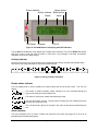
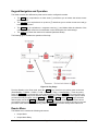
The following figure illustrates the operation of the keys.
Figure 10: Key Usage
From the Standby or the Scan mode, press the MENU key to move from one primary menu to the next
(Scan/Standby Reader Buffer Local Antenna Diag Scan/Standby...). From any menu,
press the ESCAPE key to escape back to the previous menu. Press the ENTER key to move to the submenus under each primary menu and then use the MENU key to move among sub-menu options. When
you want to modify an option, use the ENTER key. Using the MENU and the ESCAPE keys, select the
desired option and hit the ENTER key. Press the ESCAPE key to return to the upper level menu where
you started. Pressing the MENU key repeatedly will then cycle through the remaining primary menus until
you return to the main menu. Alternatively, press the ESCAPE key to return directly to the main menu.
Reader Menu
The Reader menu contains the following sub-menus:
Unique Mode
Unique Mode Delay
FS1001M User Manual
Page 12
Destron Fearing Corporation
Reader ID
Reader buzzer
Reset
Reader unique
For the following discussion, reported means the beeper is activated (if enabled), the tag ID is stored in
the buffer (if active) and sent to the communication port (if enabled).
The Unique mode defines the reaction of the reader when the same tag is read several times sequentially
on the same antenna. The Unique mode is antenna-specific.
When the Unique mode is Off, each time a tag is read it will be reported, displayed on the LCD
and the READ LED will flash.
When the Unique mode is On, a tag will be reported only if it is not the same as the previous 5
different tags detected on a given antenna. Therefore, the tag will only be reported once for each
antenna it is detected on even if it remains in the detection range of those antennas, unless 5
other different tags are read. However, the READ LED will flash and tag ID will be displayed on
the LCD every time a tag is read just as when Unique is Off.
When the Unique mode is set to Del, a tag will be reported either if it is not the same as the
previous 5 different tag IDs detected on a given antenna or if the Unique Delay has expired for
that antenna. Therefore, the tag will be reported once when it first is read on an antenna and if
the tag stays in the antenna detection range it will not be reported again until 5 other different
tags are read on that antenna or until the Unique Delay times out for that antenna; it would then
only be reported once and the cycle would repeat.
Unique Mode helps minimize the amount of identical tag IDs stored in the buffer. This is particularly
helpful in situations were a tag can remain in the detection range of an antenna for extended periods of
time. Unique Delay Mode also provides the researcher with an approximate length of time the tag
remained in the detection range of an antenna.
To change the Unique Mode setting through the front panel:
1. From the Scan/Standby display, press the MENU key until the “Reader…” sub-menu is displayed.
2. From the “Reader…” sub-menu, press the ENTER key to select it. The reader will then display the
“Reader Unique” sub-menu.
3. From the “Reader Unique” sub-menu, press the ENTER key to select it. The reader will then display
the current setting of the option (On, Off or Del), with the “*” symbol on the left and an arrow on the
right (, or ↕).
4. Use the MENU (equivalent to a down arrow “”) or the ESCAPE key (equivalent to an up arrow “”) as
indicated on the display to select the next available setting.
5. Once the desired setting is on the display, press the ENTER key to select it.
6. You can then use the MENU key to select the next Reader sub-menu or the ESCAPE key to return to
the upper level menu.
Reader unique delay
Unique Delay allows a user to select preferred value for the delay.
To change the Unique Delay value:
1. From the Scan/Standby display, press the MENU key until the “Reader…” sub-menu is displayed.
2. From the “Reader…” sub-menu, press the ENTER key to select it. The reader will then display the
“Reader Unique” sub-menu. Press the MENU key until the “Reader Unique Delay” sub-menu is
displayed.
FS1001M User Manual
Page 13
Destron Fearing Corporation
3. From the “Reader Unique Delay” sub-menu, press the ENTER key to select it. The reader will then
display the current setting of the option with an arrow on top of the most significant digit (, or ↕).
4. Use the MENU (equivalent to a down arrow “”) or the ESCAPE key (equivalent to an up arrow “”) as
indicated on the display to change the most significant digit.
5. Once the desired setting is on the display, press the ENTER key to select it. The arrow will then move
over the next digit. You can change it using the MENU or the ESCAPE key, or go to the next digit by
pressing the ENTER key.
6. Once all the digits are done, you can then use the MENU key to select the next Reader sub-menu or
the ESCAPE key to return to the upper level menu.
Note: To enable the Unique Delay Mode through the keypad see the Unique Mode above.
Reader ID in hex
The Reader ID is a user selectable hexadecimal number meant to uniquely identify a particular reader.
To change the Reader ID setting:
1. From the Scan/Standby display, press the MENU key until the “Reader…” sub-menu is displayed.
2. From the “Reader…” sub-menu, press the ENTER key to select it. The reader will then display the
“Reader Unique” sub-menu. Press the MENU key until the “Reader ID in HEX” sub-menu is displayed
3. From the “Reader ID in HEX” sub-menu, press the ENTER key to select it. The reader will then
display the current setting of the option with the “*” symbol on the left and an arrow on the right (,
or ↕).
4. Use the MENU (equivalent to a down arrow “”) or the ESCAPE key (equivalent to an up arrow “”) as
indicated on the display to change the most significant digit. The least significant digit can not be
changed and will always be “0” (Due to added Antenna ID feature).
5. Once the desired setting is on the display, press the ENTER key to select it.
6. You can then use the MENU key to select the next Reader sub-menu or the ESCAPE key to return to
the upper level menu.
Note: Reader ID default value is set up during a reader programming process. See VBFlash program
operation on page 52 for details.
Reader buzzer
The Reader Buzzer is an audible annunciator that indicates that key has been pressed, a tag has been
read, an alarm condition has occurred, a system reset has occurred, etc.
To change the Reader Buzzer setting:
1. From the Scan/Standby display, press the MENU key until the “Reader…” sub-menu is displayed.
2. From the “Reader…” sub-menu, press the ENTER key to select it. The reader will then display the
“Reader Unique” sub-menu. Press the MENU key until the “Reader Buzzer” sub-menu is displayed
3. From the “Reader Buzzer” sub-menu, press the ENTER key to select it. The reader will then display
the current setting of the option (On or Off) with the “*” symbol on the left and an arrow on the right (
or ).
4. Use the MENU (equivalent to a down arrow “”) or the ESCAPE key (equivalent to an up arrow “”) as
indicated on the display to select the next available setting.
5. Once the desired setting is on the display, press the ENTER key to select it.
You can then use the MENU key to select the next Reader sub-menu or the ESCAPE key to return to the
upper level menu.
FS1001M User Manual
Page 14
Destron Fearing Corporation
Note: The audible alarm can interfere with reader performance when a large volume of tags is being
decoded. It is recommended you turn off the buzzer during regular reader operation and use it only for set
up and maintenance purposes.
Reset parameters
To restore a reader default parameters (see table 2) through the keypad, use the following procedure:
1. From the Scan/Standby display, press the MENU key until the “Reader…” sub-menu is displayed.
2. From the “Reader…” sub-menu, press the ENTER key to select it. The reader will then display the
“Reader Unique” sub-menu. Press the MENU key until the “Reader Reset parms” sub-menu is
displayed.
3. From the “Reader Reset parms” sub-menu, press the ENTER key to select it. The reader will then
display the current setting of the option (No), with the “*” symbol on the left and an arrow on the right (
).
4. Use the ESCAPE key (equivalent to an up arrow “”) to select “Yes” or the MENU key (equivalent to a
down arrow “”) as indicated on the display to go back to the “No” setting.
5. Once the desired setting is on the display, press the ENTER key to select it.
A reader reset is performed automatically after this command is issued.
Note: Reader ID, Current Gain, Antennas Sequence and Antennas Tuned Phase settings will not be
affected by the Reset parameters command.
Buffer Menu
The FS1001M reader has a data-logging memory buffer with a maximum capacity of 5,350 tag IDs (with a
date/time stamp, reader ID and antenna ID) and up to 146 Status Reports. The data-logging buffer is
protected by a back-up lithium battery that prevents accidental data loss when the main power is low or
turned off. This button style battery is located on the CPU board and has an expected life of 5 years
(Model CR2032 made by Panasonic, Toshiba or equivalent).
The buffer is designed to store tag IDs in a ring configuration in 50-tag record blocks. That is, when the
buffer is filled to 5,350 tag records the next tag read will cause the block of memory containing the first 50
records (the oldest ones) to be erased to make room for the new tag. This process of “out with the old
and in with the new” will repeat each time the buffer reaches 5,350 records. Since the tag memory
management is performed in blocks of 50 tags when the reader indicates memory full (MMF) the actual
count of tag records in memory will be between 5,301 and 5,350.
The buffer management utilities allow the user to enable or disable the storing of tag IDs, download the
buffer contents to the communication port, and erase the contents of the buffer.
Note: The Unique Mode affects the manner in which tag IDs are stored when the buffer is active. See
the Unique Mode section on page 13 for more details.
The buffer is also designed to store reader status reports. When the Status Report Delay is set to any
value other then zero, automatic full Status Report is sent to the communication port each time the delay
times out. Each time an automatic status report is sent to the communication port a shortened version of
this report containing volatile parameters and active alarms is stored in the buffer (regardless of the Buffer
Active setting) in the same round-robin fashion as the tag buffer above. Once the report buffer fills up,
each new report only overwrites the oldest report. See page 25 for more details on full and short Status
Report contents.
Note: Status Reports are cleared from the buffer each time the reader is powered down or reset. Also,
status reports generated manually using the reader “Send status” sub-menu or the DRS command are
not stored in the buffer.
The Buffer menu contains the following sub-menus:
Active
FS1001M User Manual
Page 15
Destron Fearing Corporation
Download
Erase
Test Tag
Buffer active
To enable or disable the buffer through the front panel:
1. From the Scan/Standby display, press the MENU key until the “Buffer…” sub-menu is displayed.
2. From the “Buffer…” sub-menu, press the ENTER key to select it. The reader will then display the
“Buffer Active” sub-menu.
3. From the “Buffer Active” sub-menu, press the ENTER key to select it. The reader will then display the
current setting of the option (Yes or No), with the “*” symbol on the left and an arrow on the right ( or
).
4. Use the MENU (equivalent to a down arrow “”) or the ESCAPE key (equivalent to an up arrow “”) as
indicated on the display to select the next available setting.
5. Once the desired setting is on the display, press the ENTER key to select it.
6. You can then use the MENU key to select the next Buffer sub-menu or the ESCAPE key to return to
the upper level menu.
Buffer download
The Buffer Download function is used to copy the reader’s buffer content to a computer.
When the Buffer Download command is generated the reader sends stored tag IDs first.
The buffered tag record consists of the following:
*F0 F1 3D9.29E9227BCC 01-01-1996 00:17:41
where:
* – Asterisk indicating this is a buffered record and not a tag detected in real time
F0 – Reader ID
F1 - Antenna ID: antenna channel 1 of reader F0
3D9.29E9227BCC – Tag ID
01-01-1996 – Date the tag was detected
00:17:41 – Time the tag was detected
After all the buffered tag reports have been sent to the communication port a full status report is sent
followed by all buffered status reports. See page 25 for more details.
To initiate the buffer content download through the front panel:
1. From the Scan/Standby display, press the MENU key until the “Buffer…” sub-menu is displayed.
2. From the “Buffer…” sub-menu, press the ENTER key to select it. The reader will then display the
“Buffer Active” sub-menu. Press the MENU key until the “Buffer Download” sub-menu is displayed.
3. From the “Buffer Download” sub-menu, press the ENTER key to select it. The reader will then start
downloading. The message “Sending buffer ESC to abort” will remain on the display until the
download is completed. The download may take several minutes but does not affect the tag
detection. To stop the download press the ESCAPE key.
4. Once the buffer download is completed, the reader will automatically return to the “Buffer Download”
menu.
FS1001M User Manual
Page 16
Destron Fearing Corporation
5. You can then use the MENU key to select the next Buffer sub-menu or the ESCAPE key to return to
the upper level menu.
Buffer erase
The Buffer Erase function allows you to delete all stored tag IDs and Status Reports from a buffer.
To erase the buffer through the front panel:
1. From the Scan/Standby display, press the MENU key until the “Buffer…” sub-menu is displayed.
2. From the “Buffer…” sub-menu, press the ENTER key to select it. The reader will then display the
“Buffer Active” sub-menu. Press the MENU key until the “Buffer Erase” sub-menu is displayed.
3. From the “Buffer Erase” sub-menu, press the ENTER key to select it. The reader will then display the
current setting of the option (No) with the “*” symbol on the left and an arrow on the right ().
Use the ESCAPE key (equivalent to an up arrow “”) to select “Yes” or the MENU key (equivalent to a
down arrow “”) as indicated on the display to go back to “No” setting if you change your mind.
4. Once the desired choice is on the display, press the ENTER key to select it.
5. You can then use the MENU key to select the next Buffer sub-menu or the ESCAPE key to return to
the upper level menu.
Buffer test tag
The Buffer Test Tag option allows you to store test tag IDs in a buffer.
Note: Test tag ID is treated by a reader the same way as a real tag, so all Unique Mode rules also apply
to it. Meaning that if Unique Mode is set to On or Delay, test tag ID will be stored only once for each
antenna unless 5 other different tags are detected or the Unique Delay is expired (if the Unique Mode is
set to Delay). So to avoid this and have test tag ID stored every time it is fired and detected the Unique
Mode should be set to Delay and that delay value adjusted so it is large enough for an application
requirements but less then Test Tag Delay value. This way when automatic test tag is ready to fire
Unique Mode will be reset on all antennas and test tag ID will get stored (if it is successfully detected).
See the Unique Mode section on page 13 for more details.
To enable or disable storing test tag IDs in the buffer through the front panel:
1. From the Scan/Standby display, press the MENU key until the “Buffer…” sub-menu is displayed.
2. From the “Buffer…” sub-menu, press the ENTER key to select it. The reader will then display the
“Buffer Active” sub-menu. Press the MENU key until the “Buffer TestTag” menu is displayed.
3. From the “Buffer TestTag” sub-menu, press the ENTER key to select it. The reader will then display
the current setting of the option (Yes or No) with the “*” symbol on the left and an arrow on the right (
or ).
4. Use the MENU key (equivalent to a down arrow “”) or the ESCAPE key (equivalent to an up arrow “
”) as indicated on the display to select the next available setting;
5. Once the desired setting is on the display, press the ENTER key to select it.
6. You can then use the MENU key to select the next Buffer sub-menu or the ESCAPE key to return to
the upper level menu.
Local Menu
The Local menu is used to set the communication port operating option. The Local menu contains one
sub-menu: Send tag.
FS1001M User Manual
Page 17
Destron Fearing Corporation
Send tag setting
When the “Send tag” is enabled, tag IDs are sent to the communication serial port as they are detected
and conditioned by the Unique Mode. The tag IDs are sent in the following format (ASCII characters:
manufacturer ID followed by the universal code in hexadecimal format separated by a dot):
3D9.1BF0DB2DF0
The complete message is made up of the Reader ID, Antenna ID, Tag ID, Date and Time Stamp. The
following is an example of the same tag being read on three different antennas:
F0 F3 3D9.29E9227BCC 25-08-2003 15:23:26
F0 F1 3D9.29E9227BCC 25-08-2003 15:23:27
F0 F2 3D9.29E9227BCC 25-08-2003 15:23:27
The tag record consists of the following:
F0 F1 3D9.29E9227BCC 25-08-2003 15:23:26
where:
F0 - Reader ID
F1 - Antenna ID: antenna channel 1 of reader F0
3D9.29E9227BCC – Tag ID
25-08-2003 – Date the tag was read
15:23:26 - Time the tag was read
To change the Send tag setting:
1. From the Scan/Standby display, press the MENU key until the “Local…” sub-menu is displayed.
2. From the “Local…” sub-menu, press the ENTER key to select it. The reader will then display the
“Local Send tag” sub-menu.
3. From the “Local Send tag” sub-menu, press the ENTER key to select it. The reader will then display
the current setting of the option (Yes or No), with the “*” symbol on the left and an arrow on the right
( or ).
4. Use the MENU (equivalent to a down arrow “”) or the ESCAPE key (equivalent to an up arrow “”) as
indicated on the display to select the next available setting.
5. Once the desired setting is on the display, press the ENTER key to select it.
6. You can then use the ESCAPE key to return to the upper level menu.
Antenna Menu
The Antenna menu is used to set antennas operation parameters. It contains the following sub-menus:
Antenna Sequence
Antenna 1 Tuned Ph
Antenna 2 Tuned Ph
Antenna 3 Tuned Ph
Antenna 4 Tuned Ph
Antenna 5 Tuned Ph
Antenna 6 Tuned Ph
Antenna Scan Time
FS1001M User Manual
Page 18
Destron Fearing Corporation
Antenna Sleep Time
Antenna Sequence
The Antenna Sequence sub-menu is used to select which antennas will be active and what sequence
they will be switched between. The reader is limited to up to six physical antennas. However, to provide
additional flexibility there are up to 12 entries available in the switching sequence.
To change the Antenna Sequence setting:
1. From the Scan/Standby display, press the MENU key until the “Antenna…” sub-menu is displayed;
2. From the “Antenna …” sub-menu, press the ENTER key to select it. The reader will then display the
“Antenna Sequence” sub-menu.
3. From the “Antenna Sequence” sub-menu, press the ENTER key to select it. The reader will then
display the current setting of the option with the first digit flashing and an arrow on the right of the
sequence (, or ↕).
4. Use the MENU (equivalent to a down arrow “”) or the ESCAPE key (equivalent to an up arrow “”) as
indicated on the display to change the first position of the sequence.
5. Once the desired setting is on the display, press the ENTER key to select it. The next digit will start
flashing. You can change it using the MENU or the ESCAPE key, or go to the next digit by pressing
the ENTER key.
6. Once all the digits are done press the ENTER key, the reader will display “ESC(clr)/ENT(ok)”, press
the ENTER key to confirm or the ESCAPE key to abort antenna sequence change.
7.
Once the sequence is updated you can then use the MENU key to select the next Antenna sub-menu
or the ESCAPE key to return to the upper level menu.
Note: If using only one antenna select the following sequence: {X,0,0,0,0,0,0,0,0,0,0,0}, where X is the
channel number to which the antenna is attached.
Antenna 1 – 6 Tuned Ph
The Antenna 1-6 Tuned Ph sub-menus are used to set the target tuning phase value for each antenna.
The reader then automatically selects and constantly updates the bank of tuning capacitors for each
antenna to achieve the target phase.
To change the Antenna Tuned Ph setting:
1. From the Scan/Standby display, press the MENU key until the “Antenna…” sub-menu is displayed.
2. From the “Antenna …” sub-menu, press the ENTER key to select it. The reader will then display the
“Antenna Sequence” sub-menu. Press the MENU key until “Antenna # Tuned Ph” sub-menu is
displayed (where “# “ is the number of desired antenna).
3. From the “Antenna # Tuned Ph” sub-menu, press the ENTER key to select it. The reader will then
display the current setting of the option with an arrow on top of the most significant digit (, or ↕).
4. Use the MENU (equivalent to a down arrow “”) or the ESCAPE key (equivalent to an up arrow “”) as
indicated on the display to change the most significant digit.
5. Once the desired setting is on the display, press the ENTER key to select it. The arrow will then move
over the next digit. You can change it using the MENU or the ESCAPE key, or go to the next digit by
pressing the ENTER key.
6. Once all the digits are done, you can then use the MENU key to select the next Antenna sub-menu or
the ESCAPE key to return to the upper level menu.
Note: For the information on how to determine target phase value see Tuning procedure on page 49.
FS1001M User Manual
Page 19
Destron Fearing Corporation
Scan time
The Antenna Scan Time sub-menu is used to define for how long the reader will extend the stay at an
antenna if a tag presence is detected to attempt to decode it. If tag presence is not detected the reader
switches to the next antenna in the switching sequence every 30 milliseconds (default switching time). If
at any moment during these 30ms a tag presence is detected the reader will extend the stay at currently
active antenna and continue scanning for period of time defined by this parameter. Acceptable range is
40 to 1000ms.
Note: If necessary, the default switching time value of 30ms can be changed to 20, 25, or 44ms by
reprogramming the reader with the appropriate application firmware (see Reader Firmware Update).
To change the Scan Time setting:
1. From the Scan/Standby display, press the MENU key until the “Antenna…” sub-menu is displayed.
2. From the “Antenna …” sub-menu, press the ENTER key to select it. The reader will then display the
“Antenna Sequence” sub-menu. Press the MENU key until “Antenna Scan Time” sub-menu is
displayed.
7. From the “Antenna Scan Time” sub-menu, press the ENTER key to select it. The reader will then
display the current setting of the option with an arrow on top of the most significant digit (, or ↕).
8. Use the MENU (equivalent to a down arrow “”) or the ESCAPE key (equivalent to an up arrow “”) as
indicated on the display to change the most significant digit.
9. Once the desired setting is on the display, press the ENTER key to select it. The arrow will then move
over the next digit. You can change it using the MENU or the ESCAPE key, or go to the next digit by
pressing the ENTER key.
3. Once all the digits are done, you can then use the MENU key to select the next Antenna sub-menu or
the ESCAPE key to return to the upper level menu.
Note: Decreasing this parameter decreases overall switching cycle but also decreases the chance of a
successful tag ID decoding.
Sleep time
The Antenna Sleep Time sub-menu is used to activate and set up Antenna Sleep Mode, which helps to
conserve and extend supply battery life. In this mode the reader puts each antenna in an idle state prior
to switching to the next antenna in the switching sequence for amount of time specified by this delay. The
delay can be set to 0 (disable Sleep Mode) or from 2 - 9999 in 10ms increments.
To change the Sleep Time setting:
1. From the Scan/Standby display, press the MENU key until the “Antenna…” sub-menu is displayed.
2. From the “Antenna …” sub-menu, press the ENTER key to select it. The reader will then display the
“Antenna Sequence” sub-menu. Press the MENU key until “Antenna Sleep Time” sub-menu is
displayed.
3. From the “Antenna Sleep Time” sub-menu, press the ENTER key to select it. The reader will then
display the current setting of the option with an arrow on top of the most significant digit (, or ↕).
4. Use the MENU (equivalent to a down arrow “”) or the ESCAPE key (equivalent to an up arrow “”) as
indicated on the display to change the most significant digit.
5. Once the desired setting is on the display, press the ENTER key to select it. The arrow will then move
over the next digit. You can change it using the MENU or the ESCAPE key, or go to the next digit by
pressing the ENTER key.
6. Once all the digits are done, you can then use the MENU key to select the next Antenna sub-menu or
the ESCAPE key to return to the upper level menu.
FS1001M User Manual
Page 20
Destron Fearing Corporation
Note: While in sleep mode the antenna current is turned off so no tags can be detected. Also, activating
the sleep mode will increase the amount of time it takes to cycle through all antennas in the antenna
sequence.
Diagnostic Menu
The Diagnostic menu includes a variety of tools used for system installation and maintenance. It consists
of the following features:
Display the temperature inside the reader case (system temperature).
Display the voltage of the exciter power supply (+VE test point).
Calibrate the antenna current measurement.
Set the low antenna current alarm threshold.
Control the test tag.
Set the automatic test tag delay (periodic system verification).
Set the automatic status report delay.
Set the automatic noise report delay.
Send the reader status report though the communication port to a computer.
Calibrate the noise measurement.
Set the high noise alarm threshold.
System temperature
The Sys Temp function displays the system temperature in Celsius. For example:
D
i
a
g
S
y
s
t
e
m
p
3
7
C
e
l
c
i
u
s
To display system temperature:
1. From the Scan/Standby display, press the MENU key until the “Diag…” sub-menu is displayed.
2. From the “Diag…” sub-menu, press the ENTER key to select it. The reader will then display the “Diag
- Sys temp” sub-menu.
3. You can then use the MENU key to select the next Diag sub-menu or the ESCAPE key to return to the
upper level menu.
Note: This information is available through the communication port as part of the Status Report.
Exciter
The Exciter function displays the exciter (antenna driver) power supply voltage. For example:
Di ag - Exci t er
< 12. 1
>
The left portion is a horizontal bar graph with approximately 0.75V resolution (per horizontal dot). The
right side shows the supply value in volts. The measurement precision is approximately 0.2V. This
voltage is equivalent to the one measured between +VE and 0VE test points on the Mother board.
Under fixed conditions (antenna, system and environmental properties) higher exciter voltage translates
into greater current at the antenna and, as a result, stronger antenna magnetic field. But on the other
hand higher exciter voltage means higher power consumption of the reader and possible noise increase
FS1001M User Manual
Page 21
Destron Fearing Corporation
due to increased interference with environment and other systems and devices. Therefore, for the best
performance, exciter voltage should be optimized to the application requirements keeping in mind
explanations above. The voltage can be adjusted from 14V to 24V using potentiometer RP2 located on
the Mother board.
To display exciter voltage:
1. From the Scan/Standby display, press the MENU key until the “Diag…” sub-menu is displayed.
2. From the “Diag…” sub-menu, press the ENTER key to select it. The reader will then display the “Diag
- Sys temp” sub-menu. Press the MENU key until the “Diag - Exciter” sub-menu is displayed.
You can then use the MENU key to select the next Diag sub-menu or the ESCAPE key to return to the
upper level menu.
Note: This information is available through the communication port as part of the Status Report.
Current gain %
The Curr Gain % function is used to calibrate the antenna current peak-to-peak measurement. Current
gain value can be between 1 and 200%. The calibration formula is the following:
Idisplayed = (Imeasured * Curr gain)/100
The current gain has been calibrated at the factory. But if for any reason the system is reporting
inaccurate current values the following calibration procedure can be used to correct it.
1. Set the antenna sequence for selection of only one antenna (use the following sequence:
{X,0,0,0,0,0,0,0,0,0,0,0}, where X is the channel number to which the antenna is attached).
2. Connect a current probe to either wire from connector J2 on the Analog board and measure the real
peak-to-peak current value (Ireal) with an oscilloscope.
3. Take note of the existing Curr Gain (Old gain) from the Curr Gain menu.
4. Using the Antenna X display under the Reader Status menu, find the selected antenna current value
displayed by the reader (Idisplayed).
5. The new current gain setting should be computed as follows:
New gain = (Ireal * Old gain) / (Idisplayed)
6. After setting new current gain verify that antenna current value displayed by the reader matches the
real one measured with an oscilloscope.
To change the current gain:
1. From the Scan/Standby display, press the MENU key until the “Diag…” sub-menu is displayed.
2. From the “Diag…” sub-menu, press the ENTER key to select it. The reader will then display the “Diag
- Sys temp” sub-menu. Press the MENU key until the “Diag Curr gain %” sub-menu is displayed.
3. From the “Diag Curr Gain” sub-menu, press the ENTER key to select it. The reader will then display
the current setting of the option with an arrow on top of the most significant digit (, or ↕).
4. Use the MENU (equivalent to a down arrow “”) or the ESCAPE key (equivalent to an up arrow “”) as
indicated on the display to change the most significant digit.
5. Once the desired setting is on the display, press the ENTER key to select it. The arrow will then move
over the next digit. You can change it using the MENU or the ESCAPE key, or go to the next digit by
pressing the ENTER key.
6. Once all the digits are done, you can then use the MENU key to select the next Diag sub-menu or the
ESCAPE key to return to the upper level menu.
Note: The present Current Gain value is available through the communication port as part of the Status
Report.
FS1001M User Manual
Page 22
Destron Fearing Corporation
Alarm mA
The Alarm mA function is used to set the antenna low current alarm threshold from 1 to 9999 milliAmperes. The alarm will be generated if antenna current drops below the threshold. It can be used to
indicate reader deterioration (tuning or connection problem, etc.).
To change the current alarm:
1. From the Scan/Standby display, press the MENU key until the “Diag…” sub-menu is displayed.
2. From the “Diag…” sub-menu, press the ENTER key to select it. The reader will then display the “Diag
- Sys temp” sub-menu. Press the MENU key until the “Diag Alarm mA” sub-menu is displayed.
3. From the “Diag Alarm mA” sub-menu, press the ENTER key to select it. The reader will then display
the current setting of the option with an arrow on top of the most significant digit (, or ↕).
4. Use the MENU (equivalent to a down arrow “”) or the ESCAPE key (equivalent to an up arrow “”) as
indicated on the display to change the most significant digit.
5. Once the desired setting is on the display, press the ENTER key to select it. The arrow will then move
over the next digit. You can change it using the MENU or the ESCAPE key, or go to the next digit by
pressing the ENTER key.
6. Once all the digits are done, you can then use the MENU key to select the next Diag sub-menu or the
ESCAPE key to return to the upper level menu.
Note: The present Current Alarm Threshold value is available through the communication port as part of
the Status Report.
Note: The Current Alarm Threshold default value is set up during the reader programming process. See
page 52 for details.
Virtual test tag
The Virtual Test Tag (VTT) is a device designed to verify the reader integrity and sensitivity. It generates
an ISO FDX-B tag signal at pre-selected signal levels for each antenna and can be turned on/off by the
reader in the following manner.
1. Automatically at user selectable intervals based on the Virtual Test Tag Delay setting. This test is
done in order to verify that the reader is operating properly especially for extended periods when no
PIT tags are present.
2. Manually by the user through the keypad or the communication port connection.
When the test is performed automatically by the system or manually set to Single Shot through the
keypad or communication port, the following message is sent to the communication port for each antenna
in switching sequence (or specific antenna is the later case):
MESSAGE: Test Tag Fired on antenna 1
If the test is successful, the user will be notified by the following message on the communication port:
MESSAGE: Test Tag Found
If the test tag is not detected within the time frame defined by the Scan time parameter, the “TAG” alarm
message will be displayed on the reader’s LCD main screen and the following message will be sent to the
communication port:
PROBLEM: Test Tag Failed
If the system detects a presence of a real tag at the antenna in question the Test Tag firing will be
aborted and the following message will appear:
MESSAGE: Test aborted due to system activity
FS1001M User Manual
Page 23
Destron Fearing Corporation
When the Test tag is turned ON continuously through the keypad or the communication port, the system
performs a detection efficiency evaluation, which is a percentage of tag detections (hit rate) over a 4
second period for each antenna enabled. The hit rate value of 100% means that VTT was successfully
read once every time an antenna was selected.
Note: It is recommended to disable the buzzer as it can interfere with reader performance by presenting
audible noise, thus reducing the hit rate.
The following message is sent to the communication port when antennas 1, 2, 3, and 4 are enabled every
four seconds.
Ant1
Ant2
Ant3
Ant4
Hit
Hit
Hit
Hit
Rate:
Rate:
Rate:
Rate:
99
98
100
100
In order to exit from this test mode, the Test tag must be turned Off or the unit must be reset.
Note: The Virtual Test tag level or its signal strength is adjustable and can be set to different levels for
each antenna channel. This enables a user to utilize the VTT to determine reader sensitivity as well as to
perform end-to-end system integrity test for each individual antenna channel. However, the VTT level can
only be adjusted via the communication port from the Manual Tuning Mode or by using TL command. See
pages 23 and 44 for details.
The test tag can be turned On, Off, or S-S (Single Shot) for all antennas simultaneously or for individual
antenna through the front panel:
1. From the Scan/Standby display, press the MENU key until the “Diag…” sub-menu is displayed.
2. From the “Diag…” sub-menu, press the ENTER key to select it. The reader will then display the “Diag-Sys temp” sub-menu. Press the MENU key until the “Diag Virtual Test tag” sub-menu is displayed.
3. From the “Diag Virtual Test tag” display, press the ENTER key to select it. The reader will then display
“VTT State
ON“. Press the MENU key to select the desired action (turn VTT “ On “, “ Off “, or “ SS “ (Single Shot)) and then press the ENTER key to select the action.
4. The reader will then display “VTT Ant *All“. Use the MENU (equivalent to a down arrow “”) or the
ESCAPE key (equivalent to an up arrow “”) as indicated on the display to select “*All “ or one of the 6
antenna channels.
5. Once the desired selection is made press the ENTER to initiate the VTT action.
6. You can then use the MENU key to select the next Diag sub-menu or the ESCAPE key to return to the
upper level menu.
TstTAG delay
The TstTAG delay function is used to set the automatic virtual test tag delay period. The delay can be set
from 0 (disabled) to 1440 minutes (24 hours).
When the delay expires, the reader verifies the possible presence of real tag within each antenna field.
This is done by checking both of the following conditions for each antenna:
The number of signal transitions per second must be below 1024 (average signal frequency
below 512 Hz).
The tag-decoding algorithm must not be synchronized on the incoming signal.
If one of the conditions is not met, there is a possibility that areal tag is already within the antenna field
and the self-test for that particular antenna is aborted.
MESSAGE: Test aborted due to system activity
If both of these conditions are met, the probability of having a tag within the antenna is low and therefore,
the reader proceeds with the self-test by activating the test tag for amount of time defined by the Scan
FS1001M User Manual
Page 24
Destron Fearing Corporation
time parameter for each antenna. If the test tag is successfully read the following actions are performed
by the reader:
It will show the test tag ID on its LCD display.
It will store the test tag ID in the memory file (if “Buffer Active” and “Buffer TestTag” are enabled).
It will send the test tag ID (if “Send tag” is enabled) and test messages to the communication port:
F0> MESSAGE: Test Tag Fired on antenna 1
MESSAGE: Test Tag Found
F0 F1 3E7.0000001DF0 25-08-2003 15:23:27
If the test tag was not read within the allocated time frame (defined by the Scan time parameter), a “TAG”
(Test Tag Failed) alarm is generated and the following messages are sent to the communication port:
F0> MESSAGE: Test Tag Fired on antenna 1
PROBLEM: Test Tag Failed
This process is repeated for each antenna in the antenna sequence. The delay is then reset and the next
test will be conducted at its expiration.
To change the Test tag delay:
1. From the Scan/Standby display, press the MENU key until the “Diag…” sub-menu is displayed.
2. From the “Diag…” sub-menu, press the ENTER key to select it. The reader will then display the “Diag
- Sys temp” sub-menu. Press the MENU key until the “Diag TstTAG Delay” sub-menu is displayed.
3. From the “Diag TstTAG Delay” sub-menu, press the ENTER key to select it. The reader will then
display the current setting of the option with an arrow on top of the most significant digit (, or ↕).
4. Use the MENU (equivalent to a down arrow “”) or the ESCAPE key (equivalent to an up arrow “”) as
indicated on the display to change the most significant digit.
5. Once the desired setting is on the display, press the ENTER key to select it. The arrow will then move
over the next digit. You can change it using the MENU or the ESCAPE key, or go to the next digit by
pressing the ENTER key.
6. Once all the digits are done, you can then use the MENU key to select the next Diag sub-menu or the
ESCAPE key to return to the upper level menu.
Note: The first test will follow right after the new delay is set.
Report delay
The status report is a complete list of the present system setup and operational parameters. This report is
only available through the communication port and is presented as a compressed comma delimited
communication data stream. This format is difficult to read as is but was necessary due to program
memory constraints. It is recommended to use the “MiniMon” program release 1.5.3 or higher or the nextgeneration PTAGIS interrogation software – “M4”, available at the Pacific States Marine Fisheries
Commission Web site at www.psmfc.org, to read this report. The MiniMon and M4 programs have been
designed to interface with the Multiplexer to provide data collection services, command interface and to
break out the status report data stream into an easy to read format.
A status report can be requested through both the front panel and the communication port. The Report
Delay can be set by a user so that a status report is sent to the communication port automatically at an
interval of between 0 (disabled) and 1440 minutes (24 hours). In addition, short versions of status reports
are stored in internal memory (see page 15 for details). Status reports stored in memory only contain
dynamic parameters such as antenna current, internal system temperature, etc. (see Table 3 below) to
conserve memory.
Below is a full status report followed by a table identifying each element in the status report:
FS1001M User Manual
Page 25
Destron Fearing Corporation
$MUX1230,2,0,10,1,0030,1,1,1,1,60,240,0,103,3000,100,50,100,0,670,36A,0,670,
224,0,670,36D,50,670,1F2,0,670,36D,0,670,22B,25,1,2,3,4,5,6,0,0,0,0,0,0,22,
231,0,1,70,1,1,1,1,1,1,455,633,455,634,457,636,-1,-1,-2,-3,-2,-3,29,54,29,54,
20,47,0, 0,0,0,0,0,NL2,NL4,TAG,188,05-02-2007 16:21:39
Table 2: Full Status Report Items Description
Item
Position
Item Description
Value Range
Value Above
0
Unique String Identifier
$
1
Firmware Name
MUX1220, MUX1225, MUX1230, MUX1244
2
Firmware Version
00 – 99
2
3
Firmware Revision
00 – 99
0
4
Reader ID
00 – F0
10
5
Unique Mode
0 – OFF, 1 – ON, 2 – DELAY
1
6
Unique Mode Delay
0 – 1440 min
7
Enable Beep
0 – OFF, 1 – ON
1
8
Send To Comm
0 – NO, 1 – YES
1
9
Store Tag Mode
0 – OFF, 1 – ON
1
10
Store Test Tag
0 – OFF, 1 – ON
1
11
Test Tag Fire Delay
0 – 1440 min
60
12
Status Report Delay
0 – 1440 min
240
13
Noise Report Delay
0 – 1440 min
0
14
Current Gain
1 – 200 %
103
15
Current Alarm Threshold
1 – 9999 mA
3000
16
Noise Gain
1 – 200 %
100
17
Noise Alarm Threshold
1 – 99 %
50
18
Scan Time
40 – 1000 msec
100
19
Sleep Time
0, 2 – 9999 x 10 msec
20
Ant1 Target Phase
0 – 1023
670
21
Ant1 Present Capacitors Setting
0 – FFF (Hex Value)
36A
22
Ant1 VTT Level
0 – 99
23
Ant2 Target Phase
0 – 1023
670
24
Ant2 Present Capacitors Setting
0 – FFF (Hex Value)
224
25
Ant2 VTT Level
0 – 99
26
Ant3 Target Phase
0 – 1023
630
27
Ant3 Present Capacitors Setting
0 – FFF (Hex Value)
36D
28
Ant3 VTT Level
0 – 99
50
29
Ant4 Target Phase
0 – 1023
670
30
Ant4 Present Capacitors Setting
0 – FFF (Hex Value)
1F2
31
Ant4 VTT Level
0 – 99
32
Ant5 Target Phase
0 – 1023
670
33
Ant5 Present Capacitors Setting
0 – FFF (Hex Value)
36D
34
Ant5 VTT Level
0 – 99
FS1001M User Manual
Page 26
$
MUX1230
0030
0
0
0
0
0
Destron Fearing Corporation
35
Ant6 Target Phase
0 – 1023
670
36
Ant6 Present Capacitors Setting
0 – FFF (Hex Value)
22B
37
Ant6 VTT Level
38
39
40
41
0 – 99
25
st
1–6
1
nd
1–6
2
rd
1–6
3
th
1–6
4
th
Antenna Sequence 1 Position
Antenna Sequence 2 Position
Antenna Sequence 3 Position
Antenna Sequence 4 Position
42
Antenna Sequence 5 Position
1–6
5
43
Antenna Sequence 6th Position
1–6
6
th
1–6
0
th
1–6
0
44
45
46
47
48
Antenna Sequence 7 Position
Antenna Sequence 8 Position
th
1–6
0
th
1–6
0
th
1–6
0
th
Antenna Sequence 9 Position
Antenna Sequence 10 Position
Antenna Sequence 11 Position
49
Antenna Sequence 12 Position
1–6
0
50
System Temperature
-50 – 999 °C
22
51
Exciter Voltage
140 – 240 x 0.1 V
231
52
Lithium Battery
0 – OK, 1 – LOW
0
53
Memory Used
0 – 100 %
1
54
Stored Tags Count
0 – 5350
70
55
Antenna 1 Presence
0 – NO, 1 – YES, 2 – YES, Reader in STANDBY
1
56
Antenna 2 Presence
0 – NO, 1 – YES, 2 – YES, Reader in STANDBY
1
57
Antenna 3 Presence
0 – NO, 1 – YES, 2 – YES, Reader in STANDBY
1
58
Antenna 4 Presence
0 – NO, 1 – YES, 2 – YES, Reader in STANDBY
1
59
Antenna 5 Presence
0 – NO, 1 – YES, 2 – YES, Reader in STANDBY
1
60
Antenna 6 Presence
0 – NO, 1 – YES, 2 – YES, Reader in STANDBY
1
61
Antenna 1 Current
0 – 800 x 0.01 Ap-p
455
62
Antenna 2 Current
0 – 800 x 0.01 Ap-p
633
63
Antenna 3 Current
0 – 800 x 0.01 Ap-p
455
64
Antenna 4 Current
0 – 800 x 0.01 Ap-p
634
65
Antenna 5 Current
0 – 800 x 0.01 Ap-p
457
66
Antenna 6 Current
0 – 800 x 0.01 Ap-p
636
67
Antenna 1 Relative Phase
0 – ±1023
-1
68
Antenna 2 Relative Phase
0 – ±1023
-1
69
Antenna 3 Relative Phase
0 – ±1023
-2
70
Antenna 4 Relative Phase
0 – ±1023
-3
71
Antenna 5 Relative Phase
0 – ±1023
-2
72
Antenna 6 Relative Phase
0 – ±1023
-3
73
Antenna 1 Noise
0 – 100 %
29
74
Antenna 2 Noise
0 – 100 %
54
75
Antenna 3 Noise
0 – 100 %
29
FS1001M User Manual
Page 27
Destron Fearing Corporation
76
Antenna 4 Noise
0 – 100 %
54
77
Antenna 5 Noise
0 – 100 %
20
78
Antenna 6 Noise
0 – 100 %
47
79
Antenna 1 Relays Counter
0 – 100 %
0
80
Antenna 2 Relays Counter
0 – 100 %
0
81
Antenna 3 Relays Counter
0 – 100 %
0
82
Antenna 4 Relays Counter
0 – 100 %
0
83
Antenna 5 Relays Counter
0 – 100 %
0
84
Antenna 6 Relays Counter
0 – 100 %
0
85
Alarms Active
none, one or all
86
Elapsed Shutdown Time
sec
87
Date
DD-MM-YYYY
88
Time
HH:MM:SS (24hr format)
NL2,NL4,TAG
188
05-02-2007
16:21:39
The next is a stored status report followed by a table identifying each element in the status report. This is
a short version of the full status report and only contains the dynamic elements of the full report:
&1,24,231,0,1,70,455,633,456,632,456,634,1,-2,0,-4,0,-2,20,42,20,40,18,40,0502-2007,16:23:57
Table 3: Short Status Report Items Description
Item
Position
Item Description
Value Range
Value Above
0
Unique String Identifier
&
&
1
Report ID
1 – 146
1
2
System Temperature
-50 – 999 °C
24
3
Exciter Voltage
140 – 240 x 0.1 V
231
4
Lithium Battery
0 – OK, 1 – LOW
0
5
Memory Used
0 – 100 %
1
6
Stored Tags Count
0 – 5350
70
7
Antenna 1 Current
0 – 800 x 0.01 Ap-p
455
8
Antenna 2 Current
0 – 800 x 0.01 Ap-p
633
9
Antenna 3 Current
0 – 800 x 0.01 Ap-p
456
10
Antenna 4 Current
0 – 800 x 0.01 Ap-p
632
11
Antenna 5 Current
0 – 800 x 0.01 Ap-p
456
12
Antenna 6 Current
0 – 800 x 0.01 Ap-p
634
13
Antenna 1 Relative Phase
0 – ±1023
1
14
Antenna 2 Relative Phase
0 – ±1023
-2
15
Antenna 3 Relative Phase
0 – ±1023
0
16
Antenna 4 Relative Phase
0 – ±1023
-4
17
Antenna 5 Relative Phase
0 – ±1023
0
18
Antenna 6 Relative Phase
0 – ±1023
-2
FS1001M User Manual
Page 28
Destron Fearing Corporation
19
Antenna 1 Noise
0 – 100 %
20
20
Antenna 2 Noise
0 – 100 %
42
21
Antenna 3 Noise
0 – 100 %
20
22
Antenna 4 Noise
0 – 100 %
40
23
Antenna 5 Noise
0 – 100 %
18
24
Antenna 6 Noise
0 – 100 %
40
25
Date
DD-MM-YYYY
26
Time
HH:MM:SS (24hr format)
05-02-2007
16:23:57
To change the Status Report delay:
1. From the Scan/Standby display, press the MENU key until the “Diag…” sub-menu is displayed.
2. From the “Diag…” sub-menu, press the ENTER key to select it. The reader will then display the “Diag
- Sys temp” sub-menu. Press the MENU key until the “Diag Report Delay” sub-menu is displayed.
3. From the “Diag Report Delay” sub-menu, press the ENTER key to select it. The reader will then
display the current setting of the option with an arrow on top of the most significant digit (, or ↕).
4. Use the MENU (equivalent to a down arrow “”) or the ESCAPE key (equivalent to an up arrow “”) as
indicated on the display to change the most significant digit.
5. Once the desired setting is on the display, press the ENTER key to select it. The arrow will then move
over the next digit. You can change it using the MENU or the ESCAPE key, or go to the next digit by
pressing the ENTER key.
6. Once all the digits are done, you can then use the MENU key to select the next Diag sub-menu or the
ESCAPE key to return to the upper level menu.
Noise delay
The noise report provides noise statistics (such as average and peak noise measurement values) for
each antenna. The noise report can be requested through both the front panel and the communication
port. The Noise Delay can be set by a user so that a status report is sent to the communication port
automatically at an interval of between 0 (disabled) and 1440 minutes (24 hours) in the following form:
Noise report for Reader ID#F0
Antenna:
1
2
3
4
5
6
Average:
2 %
3 %
2 %
2 %
2 %
1 %
Peak:
10 %
3 %
5 %
3 %
2 %
3 %
To change the Noise Report Delay:
1. From the Scan/Standby display, press the MENU key until the “Diag…” sub-menu is displayed.
2. From the “Diag…” sub-menu, press the ENTER key to select it. The reader will then display the “Diag
- Sys temp” sub-menu. Press the MENU key until the “Diag Noise Delay” sub-menu is displayed.
3. From the “Diag Noise Delay” sub-menu, press the ENTER key to select it. The reader will then display
the current setting of the option with an arrow on top of the most significant digit (, or ↕).
4. Use the MENU (equivalent to a down arrow “”) or the ESCAPE key (equivalent to an up arrow “”) as
indicated on the display to change the most significant digit.
5. Once the desired setting is on the display, press the ENTER key to select it. The arrow will then move
over the next digit. You can change it using the MENU or the ESCAPE key, or go to the next digit by
pressing the ENTER key.
FS1001M User Manual
Page 29
Destron Fearing Corporation
6. Once all the digits are done, you can then use the MENU key to select the next Diag sub-menu or the
ESCAPE key to return to the upper level menu.
Send status
You can force the immediate transmission of the status report to the communication port through the
keypad using the “Send status” sub-menu. The procedure is the following:
1. From the Scan/Standby display, press the MENU key until the “Diag…” sub-menu is displayed.
2. From the “Diag…” sub-menu, press the ENTER key to select it. The reader will then display the “Diag
- Sys temp” sub-menu. Press the MENU key until the “Diag Send status” sub-menu is displayed.
3. From the “Diag Send status” sub-menu, press the ENTER key to select it. The reader will then send
the status to the communication port (“Sending status..” displayed momentarily).
4. Once the download is done, you can then use the MENU key to select the next Diag sub-menu or the
ESCAPE key to return to the upper level menu.
Noise gain %
The Noise gain % function is used to calibrate noise measurement. Noise measurement corresponds to
peak-to-peak value of a signal at receiver comparator input (test point TP21 on Analog board) in
percents, meaning that if signal at TP21 is 5V peak-to-peak (maximum possible), noise measurement
should be 100%. If signal at TP21 is 200mV peak-to-peak, noise measurement should be 4%. Noise gain
value can be set between 1 and 200%.
To change the Noise gain %:
1. From the Scan/Standby display, press the MENU key until the “Diag…” sub-menu is displayed.
2. From the “Diag…” sub-menu, press the ENTER key to select it. The reader will then display the “Diag
- Sys temp” sub-menu. Press the MENU key until the “Diag Noise gain %” sub-menu is displayed.
3. From the “Diag Noise gain %” sub-menu, press the ENTER key to select it. The reader will then
display the current setting of the option with an arrow on top of the most significant digit (, or ↕).
4. Use the MENU (equivalent to a down arrow “”) or the ESCAPE key (equivalent to an up arrow “”) as
indicated on the display to change the most significant digit.
5. Once the desired setting is on the display, press the ENTER key to select it. The arrow will then move
over the next digit. You can change it using the MENU or the ESCAPE key, or go to the next digit by
pressing the ENTER key.
6. Once all the digits are done, you can then use the MENU key to select the next Diag sub-menu or the
ESCAPE key to return to the upper level menu.
Noise Alm
The Noise Alm function is used to set the excessive noise level alarm threshold between 1 and 99%. The
alarm will be generated if noise rises above the threshold. It can be used to indicate reader deterioration
(tuning or connection problem, etc.) or ambient conditions influence.
To change the excessive noise level alarm threshold:
1. From the Scan/Standby display, press the MENU key until the “Diag…” sub-menu is displayed.
2. From the “Diag…” sub-menu, press the ENTER key to select it. The reader will then display the “Diag
- Sys temp” sub-menu. Press the MENU key until the “Diag Noise Alm” sub-menu is displayed.
3. From the “Diag Noise Alm” sub-menu, press the ENTER key to select it. The reader will then display
the current setting of the option with an arrow on top of the most significant digit (, or ↕).
4. Use the MENU (equivalent to a down arrow “”) or the ESCAPE key (equivalent to an up arrow “”) as
indicated on the display to change the most significant digit.
FS1001M User Manual
Page 30
Destron Fearing Corporation
5. Once the desired setting is on the display, press the ENTER key to select it. The arrow will then move
over the next digit. You can change it using the MENU or the ESCAPE key, or go to the next digit by
pressing the ENTER key.
6. Once all the digits are done, you can then use the MENU key to select the next Diag sub-menu or the
ESCAPE key to return to the upper level menu.
FS1001M User Manual
Page 31
Destron Fearing Corporation
SERIAL COMMUNCATION PORT OPERATION
The FS1001M reader can be fully configured and operated through the serial communication port. The
serial communication port enables you to connect to a computer for data logging, system setup, and
maintenance functions. For initial system setup utilizing the communication port is easier and more time
efficient than working through the reader’s front panel.
Hardware Description
The serial communication port is located on the bottom of the FS1001M enclosure and is a 9-pin "D" type
female connector (DB9) configured as a DCE (Data Communication Equipment). Normally, a direct cable
(pin to pin) is required to connect the communication port to a computer. The pin assignment of the
connector is as follows:
Table 4: Communication Port Connections (DB-9 Connector)
DB9 Pin
number
EIA 232
signal name
Description
Reader signal direction
PC Computer
connection
PC Computer
connection
(25 pin)
(9-pin)
2
RD
Receive Data
Output
3
2
3
TD
Transmit Data
Input
2
3
5
GND
Signal Ground
None
7
5
Configuration
The communication port is configured for operation at 57,600 baud, no parity, 8 data bits, 1 stop bit, no
flow control (57,600,N,8,1). The system is intended to be used in conjunction with the MiniMon or M4
program, which runs on the connected computer and provides interface and data interpretation,
separation and collection tools. For instance, the status reports are presented in a compressed format
and are difficult to read without the aid of the MiniMon or M4. But since all the data is presented in ASCII
format, most communication software packages such as HyperTerminal
or ProComm
can be
used to send and capture data through the communication port.
Command/response Messages
The communication port commands are used to configure the reader parameters and to perform specific
operations on the reader from a computer. The commands can be typed in ASCII format using a terminal
or a PC computer running a communication software package. A majority of commands is available from
within the MiniMon or M4 program, except for AS, BE, MT, RI and RP commands (see descriptions
below), so initial system setup must be performed using a communication software packages such as
HyperTerminal
or ProComm
.
General Format
The reader commands consist of 2 or more characters followed by Enter (Carriage Return, $0d, 12d) as
in the following example: RA0
By default, commands are echoed on the communication port as they are typed. The backspace key can
be used to correct an improper command.
FS1001M User Manual
Page 32
Destron Fearing Corporation
Command List
The following is a brief description of the commands available at the communication port ( { } - indicates a
variable parameter (1 - On/Set, 0 - Off/Reset and, # - value) ). Type in bold red indicates user entered
values and a indicates “Enter.” For a more detailed description of the commands refer to the
preceding sections.
Help (H or ?)
The H or ? command displays the list of available commands:
H or ?
F0> h
AS
AT {#}
BA {1|0}
BC
BD
BE
DA {#}
DG {#}
DR {D#|S}
DS {1|0}
DT {1|0|D#|S}
LT {1|0}
MT
NG {#}
NT {#}
NR {D#|S}
RA {1|0|R}
RB {1|0}
RI {XX}
RP
RU {1|0|D#}
SM (#)
TC
TE {1|0}
TD {DD-MM-YYYY}
TH {HH:MM:SS}
TL {ant}{lev}
H or ?
Antenna switching sequence
Antenna scanning time #msec
Buffer Active ON|OFF
Buffer Count
Buffer Download
Buffer Erase
Low current alarm threshold #mA
Current measurement gain #%
Status report DELAY|SEND
Store test tag code ON|OFF
Test tag ON|OFF|DELAY|SEND
Send tag codes to COM1 ON|OFF
Manual tuning mode
Noise measurement gain #%
High noise alarm threshold #%
Noise report DELAY|SEND
Reader Active ON|OFF|RESET
Reader Buzzer Active ON|OFF
Reader Hex ID
Reset parameters to default
Unique mode ON|OFF|DELAY
Antenna sleep mode delay #msec
Display current date and time
Test Reader Efficiency ON|OFF
Reader date
Reader time
Test tag level (0 - 99)
Display list of all commands
Note: The execution of the Help command generates a heavy processor load (interrupt processing) and
may cause temporary overload when scanning for tags.
Antenna switching sequence (AS)
The AS command is used to select which antennas will be active and what sequence they will be
switched between. The reader is limited to up to 6 physical antennas. However, to provide additional
flexibility there are up to 12 entries available in the switching sequence. The following text shows a 4
antenna system being set for a round robin switching sequence of 1,2,3,4,1,2,3,4,1,…:
F0> as
Valid
Enter
Enter
Enter
Enter
sequence value
Antenna id for
Antenna id for
Antenna id for
Antenna id for
FS1001M User Manual
are (0 Sequence
Sequence
Sequence
Sequence
6
1
2
3
4
where 0 is none)
(current: 1): 1
(current: 1): 2
(current: 1): 3
(current: 1): 4
Page 33
Destron Fearing Corporation
Enter
Enter
Enter
Enter
Enter
Enter
Enter
Enter
Antenna
Antenna
Antenna
Antenna
Antenna
Antenna
Antenna
Antenna
id
id
id
id
id
id
id
id
for
for
for
for
for
for
for
for
Sequence
Sequence
Sequence
Sequence
Sequence
Sequence
Sequence
Sequence
5 (current: 1): 0
6 (current: 1): 0
7 (current: 1): 0
8 (current: 1): 0
9 (current: 1): 0
10 (current: 1): 0
11 (current: 1): 0
12 (current: 1): 0
CONFIRM: 1 2 3 4 0 0 0 0 0 0 0 0 ? (Y/N) y
MESSAGE: Sequence table saved in EEPROM
Note: The entered values are not echoed back to the computer and are therefore not displayed. When
filling the sequence list, the selected antennas should be entered first; any remaining entries should be
filled in with “0”.
The user’s entries are displayed in the final “confirm” message. To select the new sequence enter a “Y”
or to abort the command and make no changes enter “N.”
The following text shows a four antenna system were the #1 antenna is switched to every other time to
provide a higher percentage of dwell time on #1. The switching sequence for this setup will be
1,2,1,3,1,4,1,1,2,1,3,1,4,1,1,2,…:
F0> as
Valid
Enter
Enter
Enter
Enter
Enter
Enter
Enter
Enter
Enter
Enter
Enter
Enter
sequence value
Antenna id for
Antenna id for
Antenna id for
Antenna id for
Antenna id for
Antenna id for
Antenna id for
Antenna id for
Antenna id for
Antenna id for
Antenna id for
Antenna id for
are (0 Sequence
Sequence
Sequence
Sequence
Sequence
Sequence
Sequence
Sequence
Sequence
Sequence
Sequence
Sequence
6 where 0 is none)
1 (current: 1): 1
2 (current: 2): 2
3 (current: 3): 1
4 (current: 4): 3
5 (current: 0): 1
6 (current: 0): 4
7 (current: 0): 1
8 (current: 0): 0
9 (current: 0): 0
10 (current: 0): 0
11 (current: 0): 0
12 (current: 0): 0
CONFIRM: 1 2 1 3 1 4 1 0 0 0 0 0? (Y/N) y
MESSAGE: Sequence table saved in EEPROM
Note: If using only one antenna select the following sequence: {X,0,0,0,0,0,0,0,0,0,0,0}, where X is the
channel number to which the antenna is attached.
Antenna scanning time (AT)
The AT command defines for how long the reader will extend the stay at an antenna if a tag presence is
detected to attempt to decode it. If tag presence is not detected the reader switches to the next antenna
in the switching sequence every 30 milliseconds (default switching time). If at any moment during these
30ms a tag presence is detected the reader will extend the stay at currently active antenna and continue
scanning for period of time defined by this parameter. Acceptable range is 40 to 1000ms as in the
following example (do not include the leading zeroes):
F0> at100
MESSAGE: Scanning time set to 100 ms.
F0> MESSAGE: Reader is in standby mode
MESSAGE: Reader is in scan mode
FS1001M User Manual
Page 34
Destron Fearing Corporation
F0> at25
MESSAGE: Bad #. Acceptable range is 40 to 1000 ms
Note: Decreasing this parameter reduces overall switching cycle but also reduces the chance of a
successful tag ID decoding.
Buffer active (BA)
The BA command is used to enable or disable the storing of tag IDs in a buffer.
To enable the buffer:
F0> ba1
MESSAGE: Buffer was turned ON
To disable the buffer:
F0> ba0
MESSAGE: Buffer was turned OFF
Buffer count (BC)
The BC command is used to display the number of tag IDs stored in a buffer.
To see the buffer count:
F0> bc
MESSAGE: Tag count is 4610
Buffer download (BD)
The BD command is used to send all information stored in a buffer to the communication port:
F0> bd
MESSAGE: Download initiated press ESC to quit
*F0 F2 3D9.1BF264C7F0 22-01-2007 10:04:16
*F0 F6 3D9.1BF264C7F0 22-01-2007 10:04:19
*F0 F1 3D9.1BF269C039 22-01-2007 10:04:20
*F0 F6 3D9.1BF269C039 22-01-2007 10:04:23
*F0 F2 3D9.1BF269C039 22-01-2007 10:04:24
*F0 F5 3D9.1BF264C7F0 22-01-2007 10:04:26
*F0 F6 3D9.1BF264C7F0 22-01-2007 10:04:29
$MUX1230,2,0,10,1,0030,1,1,1,1,60,240,0,103,3000,100,50,100,0,670,36A,0
,670,224,0,670,36D,50,670,1F2,0,670,36D,0,670,22B,25,1,2,3,4,5,6,0,0,0,
0,0,0,22,231,0,1,70,1,1,1,1,1,1,455,633,455,634,457,636,-1,-1,-2,-3,2,-3,29,54,29,54,20,47,0,0,0,0,0,0,NL2,NL4,TAG,188,05-02-2007 16:21:39
&1,26,231,0,0,7,473,595,474,595,474,596,0,-5,-2,-1,1,1,9,20,8,27,12,23,
22-01-2007,10:05:00
&2,26,231,0,0,7,473,594,473,596,474,595,0,-4,1,3,2,3,10,37,11,51,11,45,
22-01-2007,10:10:00
&3,26,231,0,0,7,473,595,473,596,474,595,2,-3,2,0,3,2,10,45,11,53,12,43,
22-01-2007,10:15:00
&4,26,231,0,0,7,473,593,473,595,473,596,2,-3,2,0,2,2,10,35,11,43,10,39,
22-01-2007,10:20:00
Message: Buffer download complete
Buffer erase (BE)
The BE command is used to erase all information stored in a buffer:
F0> be
CONFIRM: Erase Buffer? (Y/N) y
MESSAGE: Buffer erased.
F0> be
CONFIRM: Erase Buffer? (Y/N) n
FS1001M User Manual
Page 35
Destron Fearing Corporation
MESSAGE: Command cancelled.
FF>
Low current alarm threshold (DA)
The DA command is used to set low antenna current alarm threshold. The acceptable range is 1 to 9999
in milleamperes peak-to-peak, as illustrated in the following examples:
F0> da100
MESSAGE: Current alarm threshold set to 100mA
F0> da6000
MESSAGE: Current alarm threshold set to 6000mA
F0> PROBLEM: Ant2 current low
F0> da12000
MESSAGE: Bad #. Acceptable range is 1 to 9999mA
F0>
The alarm threshold can be used to indicate reader deterioration (tuning or connection problem, etc.).
When the antenna N current is lower than the alarm threshold, the EXN is displayed on reader’s LCD and
“AntN current low” alarm is generated and sent to communication port as in the above example.
Note: The alarm threshold default value is set up during the reader programming process.
Current measurement gain (DG)
The DG command is used to calibrate antenna current measurement by adjusting current gain. The
calibration formula is the following:
Idisplayed = (Imeasured * Curr gain)/100
The default value is 110%. The acceptable range is 1 to 200% and can be changed, as illustrated in the
following example:
F0> dg100
MESSAGE: Current gain set to 100%
F0> dg1000
MESSAGE: Bad #. Acceptable range is 1 to 200%
F0>
Status report delay (DRD)
The DRD command is used to set the automatic status report delay period. The status report is sent
automatically to the communication port and provides complete status information about the reader. The
automatic sending of the report can be set from 0 (disable) to 1440 minutes (24 hours). For example:
F0> drd1
MESSAGE: Report delay set to 1 minute(s)
F0> drd1440
MESSAGE: Report delay set to 1440 minute(s)
F0> drd5000
MESSAGE: Bad #. Acceptable range is 1 to 1440min
Status report send (DRS)
The DRS command displays the current reader status and configuration. For example:
F0> drs
$MUX1230,2,0,10,1,0030,1,1,1,1,60,240,0,103,3000,100,50,100,0,670,36A,0
,670,224,0,670,36D,50,670,1F2,0,670,36D,0,670,22B,25,1,2,3,4,5,6,0,0,0,
0,0,0,22,231,0,1,70,1,1,1,1,1,1,455,633,455,634,457,636,-1,-1,-2,-3,2,-3,29,54,29,54,20,47,0, 0,0,0,0,0,NL2,NL4,TAG,188,05-02-2007 16:21:39
Note: For more information about the status report and its contents refer to page 25.
FS1001M User Manual
Page 36
Destron Fearing Corporation
Store test tag code (DS)
The DS command is used to enable or disable the storing of test tag IDs in a buffer.
To enable storing test tag IDs:
F0> ds1
MESSAGE: Buffering of test Tag ID was turned ON
To disable storing test tag IDs:
F0> ds0
MESSAGE: Buffering of test Tag ID was turned OFF
Test tag on/off/single shot (DT)
The DT command controls the Virtual Test Tag (VTT) operation.
To turn VTT On:
F0> dt1
MESSAGE:
Ant1 Hit
Ant2 Hit
Ant3 Hit
Ant4 Hit
Ant5 Hit
Ant6 Hit
Test
Rate
Rate
Rate
Rate
Rate
Rate
Tag On for ALL Antennas
: 100
: 100
: 100
: 100
: 100
: 100
When the virtual test tag is turned On the system performs a detection efficiency evaluation, which is a
percentage of tag detections (hit rate) over a 4 second period for each antenna enabled. The hit rate
value of 100% means that VTT was successfully read once every time an antenna was selected.
Note: It is recommended to disable the buzzer as it can interfere with reader performance by presenting
audible noise, thus reducing the hit rate.
To turn VTT Off:
F0> dt0
MESSAGE: Test Tag Off for ALL Antennas
To single-shoot VTT (activate once for each antenna in the antenna switching sequence):
F0> dts
MESSAGE: Test Tag Single shot for ALL Antennas
MESSAGE: Test Tag Fired on antenna 1
MESSAGE: Test Tag Found
MESSAGE: Test Tag Fired on antenna 2
PROBLEM: Test Tag Failed
MESSAGE: Test Tag Fired on antenna 3
MESSAGE: Test aborted due to system activity
MESSAGE: Test Tag Fired on antenna 4
PROBLEM: Test Tag Failed
MESSAGE: Test Tag Fired on antenna 5
MESSAGE: Test aborted due to system activity
MESSAGE: Test Tag Fired on antenna 6
MESSAGE: Test Tag Found
Test tag delay (DTD)
The DTD command is used to set the automatic test tag delay period. The reader automatically performs
a test tag single shot for all antennas in the switching sequence each time the delay expires (the same
way as DTS command). The delay can be set from 0 (disable) to 1440 minutes (24 hours). For example:
F0> dtd10
MESSAGE: Test tag timer set to 10 minute(s)
MESSAGE: Test Tag Fired on antenna 1
FS1001M User Manual
Page 37
Destron Fearing Corporation
MESSAGE:
MESSAGE:
MESSAGE:
MESSAGE:
MESSAGE:
MESSAGE:
MESSAGE:
MESSAGE:
MESSAGE:
MESSAGE:
MESSAGE:
Test
Test
Test
Test
Test
Test
Test
Test
Test
Test
Test
Tag
Tag
Tag
Tag
Tag
Tag
Tag
Tag
Tag
Tag
Tag
Found
Fired
Found
Fired
Found
Fired
Found
Fired
Found
Fired
Found
on antenna 2
on antenna 3
on antenna 4
on antenna 5
on antenna 6
F0> dtd5000
MESSAGE: Bad #. Acceptable range is 0 to 1440min
Send tag codes to COM1 (LT)
The LT command is used to enable and disable the sending of real-time tag IDs to the communication
port. For example:
F0> lt1
MESSAGE: Sending of tags enabled.
F0> lt0
MESSAGE: Sending of tags disabled.
FF>
Note: If Unique mode is activated, the tag ID is sent to the communication port only if it is different from
the previous five other different tag IDs, or if Unique Delay expires.
Manual tuning mode (MT)
Note: See page 49 for additional tuning information.
The MT command is used to tune the antenna. The Manual Tuning menu contains all necessary antenna
tuning commands and parameters. There are two modes in which tuning can be performed:
First mode is activated by turning Dynamic Tuning “On” by pressing the “D” key until “DynTun ON”
appears. In this mode tuning is accomplished by changing the target phase (Tuned Ph 670) using the
appropriate “decrement/increment” keys for Phase. The Dynamic Tuning then adjusts tuning capacitor
settings automatically to achieve selected phase value.
Manual Tuning Function Command Key:
+
Q
A
E
Z
Y
T
D
C
N
.
W
S
R
X
U
Change Antenna to tune
decrement/increment by 1 Phase set point
decrement/increment by 10 Phase set point
decrement/increment by 100 Phase set point
decrement/increment by 0.1 Phase Slope
decrement/increment VTT Level
Turn ON/OFF VTT
Turn ON/OFF Dynamic Tuning
Max current tune this Antenna
Save PH, slope, cap setup and vtt level for this antenna
QUIT
DynTun ON VTT OFF Lev
0 Tuned Ph 670
Ant1 Cap 0x0372 Ph
-3 Slope 5.0 Cur 4.73A (580) Noi
13% Eff
FS1001M User Manual
Destron Fearing Corporation
Page 38
0 Header
0
Second mode is activated by turning Dynamic Tuning “Off” by pressing the “D” key until “DynTun OFF”
appears. In this mode tuning is done by manually adjusting the tuning capacitance (Ant1 Cap 0x0372)
using appropriate “decrement/increment” keys for Capacitance. This is a somewhat crude method and
can be confusing since a higher capacitance setting doesn’t always mean more capacitance was
switched in. This is because the higher capacitor values do not have the same magnitude or weight as
the associated binary digit. The biggest change can be noticed when crossing the larger number
boundaries, such as going from 0x04FF to 0x0500 setting. There are 12 tuning capacitors; therefore the
maximum capacitance setting in hex is 0x0FFF. You can determine the actual capacitance switched into
the circuit from the following table. A binary “1” indicates the capacitor is switched in and a “0” means it is
switched out.
Binary Digit Position
1
2
3
4
5
6
7
8
9
10
11
12
Capacitance, pF
56
120
220
400
780
1,500
2,820
5,400
10,180
19,200
36,300
69,000
So, a hex capacitance setting of 0x0291 is binary 0000 0010 1001 0001 and, as shown above, has a
capacitive value of 19,200 + 5,400 + 780 + 56 = 25,436 pF. The unit has a fixed capacitance of 12,000 pF
which is added to the tuning capacitance value, thus the total capacitance of 0x0291 setting is 37,436 pF.
Manual Tuning Function Command Key:
+
Q
A
E
Z
Y
T
D
C
N
.
W
S
R
X
U
Change Antenna to tune
decrement/increment by 0x001 CAPACITOR SETUP
decrement/increment by 0x010 CAPACITOR SETUP
decrement/increment by 0x100 CAPACITOR SETUP
decrement/increment by 0.1 Phase Slope
decrement/increment VTT Level
Turn ON/OFF VTT
Turn ON/OFF Dynamic Tuning
Max current tune this Antenna
Save PH, slope, cap setup and vtt level for this antenna
QUIT
DynTun OFF VTT OFF Lev
0 Tuned Ph 670
Ant1 Cap 0x0372 Ph
-3 Slope 5.0 Cur 4.73A (580) Noi
12% Eff
0 Header
1
The last two lines of the display give the real time antenna data.
The first line displays:
DynTun
OFF VTT OFF Lev
0 Tuned Ph
670
Where:
DynTun
Dynamic Tuning setting (ON or OFF)
VTT
Virtual Test Tag setting (ON or OFF)
Lev
VTT level setting (0-99, see below)
FS1001M User Manual
Page 39
Destron Fearing Corporation
Tuned Ph
Target phase value setting (typically around 650)
The second line is continuously updated and displays:
Ant1 Cap 0x0372 Ph
-3 Slope 5.0 Cur 4.73A (580) Noi
12% Eff
0 Header
1
Where:
Ant1
Selected antenna number (1-6)
Cap
Present capacitance setting in hex (0x0000 – 0x0FFF) (12,000 pF – 157,976 pF)
Ph
Relative phase difference between the last measured phase and the target phase from
the above line
Slope
Slope setting (see below)
Cur
Antenna current measurement (Amperes peak-to-peak)
(580)
Analog to digital converter value of the measured antenna current (this is a hold over
from the development phase of the project)
Noi
Average noise measurement (See Noise Gain % on page 30)
Eff
Reading efficiency if a tag is read
Header
Number of tag headers seen in the last reading efficiency update (used to determine the
reading efficiency (tag reads/headers x 100))
The VTT level setting (VTT … Lev) is inversely proportional to the VTT signal strength. Thus, the larger
the VTT level number the weaker the VTT signal seen by the reader.
The Slope value determines how far the relative phase from line 2 must differ from the target phase of
line 1 before the reader adjusts the tuning and to some degree determines how aggressively the tuning is
adjusted. So, a slope of “3” means the reader will not adjust the tune (capacitance settings) until the
relative phase is equal to or larger then ±3. But note that if this value is too low the Multiplexer may not be
able to stay in tune and achieve target phase (this depends on the antenna, capacitors setting in the
Multiplexer, etc.). If this happens the Slope value needs to be increased. The recommended value is
between 3.0 and 5.0.
Remember to save any changes by pressing key “N” before going to the next antenna or exiting Manual
Tuning menu.
When you exit the Manual Tuning menu, Dynamic Tuning automatically turns on.
Note: See page 49 for additional tuning information.
Noise measurement gain (NG)
The NG command is used to calibrate the average noise measurement by adjusting noise gain. (See
Noise Gain % on page 30 for more details.) The default value is 100%. The acceptable range is 1 to
200% and can be changed, as illustrated in the following examples:
F0> ng100
MESSAGE: Current gain set to 100%.
F0> ng500
MESSAGE: Bad #. Acceptable range is 1 to 200%
F0>
High noise alarm threshold (NT)
The NT command is used to set the excessive noise level alarm threshold. The acceptable range is 1 to
99%, as illustrated in the following examples:
FS1001M User Manual
Page 40
Destron Fearing Corporation
F0> nt50
MESSAGE: Current noise alarm threshold set to 50%
F0> nt10
MESSAGE: Current noise alarm threshold set to 10%
F0> PROBLEM: Ant1 noise level
F0> nt0
MESSAGE: Bad #. Acceptable range is 1 to 99%
The alarm threshold can be used to indicate reader deterioration (tuning or connection problem, etc.).
When the noise level is higher than the alarm threshold, the NL1-6 (Ant1-6 noise level) alarm is
generated, as illustrated in the above example.
Noise report delay (NRD)
The NRD command is used to set the automatic noise report delay period. The noise report is sent
automatically to the communication port and provides noise statistics for each antenna, such as average
and peak noise measurement values. The delay can be set from 0 (disable) to 1440 minutes (24 hours).
For example:
F0> nrd60
MESSAGE: Noise Report delay set to 60 minute(s)
F0> Noise report for Reader ID#F0
Antenna:
1
2
3
4
5
6
Average:
10 % 51 % 10 % 52 % 11 % 45 %
Peak:
11 % 51 % 14 % 53 % 16 % 48 %
F0> nrd5000
MESSAGE: Bad #. Acceptable range is
F0> Noise report for Reader ID#F0
Antenna:
1
2
3
4
Average:
12 % 62 % 12 % 59 %
Peak:
21 % 100 % 23 % 93 %
0 to 1440min
5
12 %
19 %
6
53 %
92 %
Noise report send (NRS)
The NRS command displays the current noise report. For example:
F0> nrs
Noise report for Reader ID#F0
Antenna:
1
2
3
4
5
6
Average:
11 % 64 % 11 % 62 % 11 % 58 %
Peak:
20 % 92 % 27 % 80 % 28 % 92 %
Reader active (RA)
The RA command is used to enable or disable scanning for tags. The command is also used to reset the
reader. For example:
F0> ra1
F0> MESSAGE: Reader is in scan mode
F0> ra0
F0> MESSAGE: Reader is in standby mode
F0> rar
MESSAGE: Reader shutdown!
F0> MESSAGE: MUX1230 2.0
MESSAGE: Reader reset!
MESSAGE: Reader is in scan mode
Reader buzzer active (RB)
The RB command is used to enable or disable the reader’s buzzer:
F0> rb1
FS1001M User Manual
Page 41
Destron Fearing Corporation
MESSAGE: Beep sound enable
F0> rb0
MESSAGE: Beep sound disable
Note: An audible alarm generated by the buzzer can interfere with reader performance when a large
volume of tags is being decoded. It is recommended you turn off the buzzer during regular reader
operation and instead use the buzzer for set up and maintenance purposes.
Reader Hex ID (RI)
The RI command is used to set the reader ID number. It is entered in hexadecimal format, where the
most significant (left) hex digit in 'xx' is in the range 0-F and the least significant (right) must be 0. This is
illustrated in the following commands, which set the reader ID to E0:
F0> rie0
CONFIRM: Reader ID = E0? (Y/N)y
MESSAGE: Reader ID = E0.
E0> MESSAGE: Reader is in standby mode
MESSAGE: Reader is in scan mode
F0> riee
MESSAGE: Invalid argument
Note: The reader ID default value is set up during the reader programming process.
Reset parameters to default (RP)
The RP command is used to reset the reader parameters to the default values. For example:
F0> rp
CONFIRM: Reset default parameters? (Y/N)y
MESSAGE: Reader reset to default parameters
MESSAGE: Reader shutdown!
F0> MESSAGE: MUX1230 2.0
MESSAGE: Reader reset!
MESSAGE: Reader is in scan mode
A reader reset is automatically performed after this command.
Note: The Reader ID and the antenna parameters, such as antennas switching sequence and antennas
target phase, will not be affected by the reset parameter command. To reset all parameters to default you
need to power down the reader and remove the back-up lithium battery from the CPU board for a few
seconds; this will also reset the internal clock.
For a complete list of default parameters, see page 11.
Reader unique on/off (RU)
The RU command is used to enable or disable unique mode. For example:
F0> ru1
MESSAGE: Unique mode turned ON
F0> ru0
MESSAGE: Unique mode turned OFF
Reader unique delay (RUD)
The RUD command is used to set up and enable unique mode delay. The automatic delay can be set
from 1 to 1440 minutes (24 hours). For example:
F0> rud10
MESSAGE: Unique mode delay set to 10 min(s)
F0> rud0
MESSAGE: Bad #. Acceptable range is 1 to 1440 min(s)
FS1001M User Manual
Page 42
Destron Fearing Corporation
Antenna sleep mode delay (SM)
The SM command is used to activate and set up sleep mode, which helps to conserve and extend battery
life. In this mode the reader puts each antenna in an idle state prior to switching to the next one for
amount of time specified by this delay. The delay can be set to 0 (disable) or from 2 - 9999 in 10ms
increments. For example:
F0> sm0
MESSAGE: Sleep set to 0 ms
F0> MESSAGE: Reader is in standby mode
MESSAGE: Reader is in scan mode
F0> sm10
MESSAGE: Sleep set to 100 ms
F0> MESSAGE: Reader is in standby mode
MESSAGE: Reader is in scan mode
F0> sm1
MESSAGE: Bad #. Acceptable range is 0, 2 to 9999
Note: While in sleep mode the antenna current is turned off so no tags can be detected. Also, activating
the sleep mode will increase the amount of time it takes to cycle through all antennas in the antenna
sequence.
Display current date and time (TC)
The TC command is used to display the current date and time from the reader’s internal clock. For
example:
F0> tc
23-01-2007 14:54
Test reader efficiency (TE)
The TE command is used to activate the reader efficiency test. For example:
F0> te1
Efficiency test enabled
Ant1 Hit Rate : 100
Ant2 Hit Rate : 100
Ant3 Hit Rate : 100
Ant4 Hit Rate : 100
Ant5 Hit Rate : 100
Ant6 Hit Rate : 100
F0> te0
Efficiency test disabled
This test generates a Hit Rate report for each antenna in the antenna sequence. This is the same report
as the one generated when VTT is activated with a DT1 command. The only difference is that in this case
real tags need to be placed into each antenna field. This option can be used to test each individual
antenna’s performance (field strength, shape, etc.) or to test tag performance.
Note: It is recommended that you disable the buzzer, as it can interfere with reader performance by
presenting audible noise, thus reducing the hit rate.
Reader date (TD)
The TD command is used to set the date on the reader’s internal clock. The date is set using the following
format: DD-MM-YYYY. For example, to set the reader date to January 23, 2007 you would enter the
following:
F0> td23-01-2007
Note: There is a back-up lithium battery on the CPU board that keeps the clock running when the reader
power is low or turned off. This button style battery has an expected life of 5 years (Model CR2032 made
by Panasonic, Toshiba or equivalent).
FS1001M User Manual
Page 43
Destron Fearing Corporation
Reader time (TH)
The TH command is used to set the time on the reader’s internal clock. The time is set using the following
24-hour format: HH:MM:SS. For example, to set the reader time to 16 hours, 30 minutes and 30 seconds
you would enter the following:
F0> th16:30:30
Note: There is a back-up lithium battery on the CPU board that keeps the clock running when the reader
power is low or turned off. This button style battery has an expected life of 5 years (Model CR2032 made
by Panasonic, Toshiba or equivalent).
Test tag level (TL)
The TL command is used to set the VTT level for each individual antenna 1 through 6. Acceptable
antenna numbers are 1 to 6 and acceptable level settings are 0 to 99. For example, to set the VTT level
of antenna 6 to 25 you would enter the following:
F0> tl625
MESSAGE: antenna #6 Vtt Level Set
F0> MESSAGE: Reader is in standby mode
MESSAGE: Reader is in scan mode
F0> tl810
MESSAGE: Unexpected or Missing argument
F0> tl2100
MESSAGE: VttLevel must be 0-99
Note: The VTT level setting is inversely proportional to the VTT signal strength. Thus, the larger the VTT
level number the weaker the VTT signal seen by the reader: VTT level setting of 0 generates the
strongest VTT signal and a VTT level setting of 99 generates the weakest VTT signal.
FS1001M User Manual
Page 44
Destron Fearing Corporation
SELF TESTS AND DIAGNOSTICS
The FS1001M has integrated self-tests that are used to verify the integrity of the hardware and to perform
antenna tuning and adjustments. Two types of tests are performed on the unit:
Power-up diagnostics that are performed each time the unit is reset.
Periodic self-tests that are performed while the unit is in operational mode. These tests are
performed automatically by the unit and some of them also can be activated by a user request.
Power-up Diagnostics
When the FS1001M is turned on or reset, the reader performs an automatic start-up procedure that
includes self-tests of the following components:
Flash EPROM memory
RAM memory
Power supply
Back-up lithium battery
The detailed power-up sequence is illustrated in the next figure.
Figure 11: Power-up sequence
Startup Sequence
The FS1001M microprocessor will start as soon as the power is applied to the unit. If the input power is
not at a sufficient level to start the microprocessor (11V or less), the LCD backlight will not turn on and
usually a series a black squares will be displayed on the first LCD line as following:
FS1001M User Manual
Page 45
Destron Fearing Corporation
If this problem is encountered, check the system power supply (+12VR and 0VR test points on the Mother
board). If the voltage level is 11 V or higher, this problem may indicate that the Flash EPROM is bad or
that there is a severe CPU board problem. You should then replace the CPU board.
Flash EEPROM Memory Test
Once the CPU is started, the processor performs a “Boot Manager” memory verification. The “Boot
Manager” is a section of program included in the Flash EEPROM memory (Electronically Erasable
Programmable Read-Only Memory) that can never be erased and which initializes the reader hardware. If
the “Boot Manager” program is invalid, the system is halted and the CPU board needs to be replaced.
Once this verification is completed, the unit checks if there is a valid application program. The application
program governs the operation of the reader and can be updated in the field using the VBFlash program
running on any PC compatible computer with Microsoft Windows (see page 52 for details).
Note: The “Boot Manager” and the application program version/revision numbers are displayed during
the power-up sequence.
If there is no valid application program, the reader will automatically enter in the firmware update mode,
waiting for a download from VBFlash.
RAM Memory Test
When the Flash EEPROM memory is verified, the reader proceeds with the RAM memory (RandomAccess Memory) verification. The RAM test is a non-destructive test that performs read/write operations
with known bit patterns in every memory location. Before writing in a memory location, its content is saved
in one of the processors internal registers. A series of write/check back read operations are then done in
that memory location before the original content is re-written. If a memory failure is detected, the beeper
will be activated permanently.
Upon detection of a RAM failure, no clear message can be displayed since the CPU could lose control of
the program; therefore, the beeper is used to indicate the problem. If such a failure occurs, the CPU
board must be replaced.
Power Supply Verification
The next step in the power-up sequence is the power supply verification. This test is also done
periodically during the normal operation of the reader unit. If the exciter supply voltage +VE drops below
12V, an alarm will be generated.
Back-up Lithium Battery Verification
The reader performs checks of the back-up lithium battery. This battery protects the collected data and
user parameters’ settings stored in RAM memory and keeps the reader internal clock running when the
reader input power is low or turned off. If the battery voltage is low (under 3V) an alarm will be generated.
If back-up battery voltage is low at power-up all previously stored data and user parameters’ settings are
lost, so default parameters settings will be reloaded and the following message will be sent to the
communication port:
MESSAGE: Parameters reloaded.
The lithium battery connection should then be checked. If the connection is fine then the battery needs to
be replaced. The back-up lithium battery has an expected shelf life of 5 years, which is reduced when the
unit is powered off for a long period of time since current is drawn from it in order to preserve the RAM
memory content. The back-up battery compartment is located on the CPU board. It should be replaced
with a CR2032 type lithium battery (Panasonic or any other battery manufacturer with UL approval). A
new battery is usually 3.25V and becomes weak when its voltage drops under 3V.
FS1001M User Manual
Page 46
Destron Fearing Corporation
Periodic Self-tests
When the unit is in operational mode, periodic self-tests are performed, including:
Virtual test tag detection
System parameters monitoring
Critical antenna current protection
Elapsed Shutdown Time (ESDT)
Antenna switching relays usage counter
Virtual test tag detection
The Virtual Test Tag (VTT) is a device designed to verify the reader integrity and sensitivity. It generates
an ISO FDX-B tag signal at pre-settable signal levels for each antenna that can be turned on/off by the
reader. It does this in the following manner:
Automatically at user-selectable intervals based on the Virtual Test Tag Delay setting. This test is
done in order to verify that the reader is operating properly, especially for extended periods when
no PIT tags are present.
Manually by the user using the keypad or the communication port connection.
System parameter monitoring
The reader measures and monitors a list of key hardware parameters on a continuous basis. The
following parameters are monitored:
Antenna current on each antenna channel in the antenna sequence
Average noise on each antenna channel in the antenna sequence
Temperature inside the reader enclosure
Communication between the Analog board and CPU board
Communication between the ASB board and CPU board
Exciter power supply voltage
Back-up lithium battery voltage
Critical antenna current protection
This feature is implemented to protect sensitive parts of the circuitry (receiver front end). When current of
an antenna X reaches 7.0 Ap-p “AntX high cur” (HCX) alarm is being generated. When current reaches 7.5
Ap-p reader goes in Standby mode and a message is displayed on the LCD asking user to reduce Exciter
Voltage by turning RP2 on the Mother board clockwise and to reactivate the reader by pressing the READ
button.
Note: Antenna current measurement needs to be calibrated accurately in order for this feature to function
correctly.
Elapsed Shutdown Time (ESDT)
This feature provides the total time a reader was off. This allows a user to see if there were any
performance interruptions due to power outages and for how long.
Every time a reader is turned on the time difference between current time and time it was shut down is
added to ESDT counter. ESDT value is added to Status Report just before the Current Time value. This
value is in seconds. To reset the counter Buffer Download (BD) or Status Report (DRS) command has to
be generated from the console; automatically generated status reports will not reset the counter.
FS1001M User Manual
Page 47
Destron Fearing Corporation
Note: After the counter is reset the previous ESDT value will still be available until a reader is turned off.
Antenna switching relays usage counter
Relays usage counter records the number of times each antenna switching relays were activated. When
any of these numbers reaches 100,000,000 the message is generated notifying that the relays are near
their life expectancy limit and need to be replaced soon.
Note: The counter data is stored on CPU board in RAM memory therefore is dependant on the lithium
battery life and is not linked to actual hardware, so if the lithium battery is replaced while the reader is
powered down or the CPU board is exchanged the counter values will not be accurate.
Alarm Messages
Alarm messages are issued by the reader and displayed on the LCD in form of a code and sent to the
serial communication port in form of a message when abnormal conditions are detected. The messages
are in ASCII format.
Table 5: Alarm Messages Description
Code
Message
Description
ANC
Analog comm
Analog board communication problem (disconnected or failed). Also
caused by a power supply voltage drop below 12V.
ASB
ASB comm
Antenna Switching Board (ASB) communication problem (improperly
connected, disconnected, or failed).
EPW
Exc. Power low
Low exciter voltage level: Mother board power supply should be checked
(+VE).
EX1-6
Ant 1-6 current low
Current of the indicated antenna is below the alarm threshold level. It
may be caused by an out-of-tune antenna, a bad antenna or antenna
connection, reader failure, or an improper threshold parameter setting.
HC1-6
Ant1-6 high cur
Current of the indicated antenna is above 7.0Ap-p.
HTP
High temperature
System temperature level inside the enclosure is above +65˚C.
LIT
Low lithium
Voltage level of the memory/real-time clock back-up lithium battery is
low.
LTP
Low temperature
System temperature level inside the enclosure is below -10˚C.
MMF
Memory full
Memory used to store tag IDs is full.
MML
Memory low
Memory used to store tag IDs is 95% full.
NL1-6
Ant 1 – 6 noise level
Average noise level at the specified antenna is above the noise alarm
threshold level. It may be caused by a noisy environment, a tag present
in the antenna field for a long time, antenna or reader failure, or an
improper threshold parameter setting.
OVR
Overrun
Overrun of the reader CPU. May be caused by environmental or system
noise.
TAG
Test Tag Failed
Virtual test tag has not been decoded successfully.
FS1001M User Manual
Page 48
Destron Fearing Corporation
MAINTENANCE
Maintenance of the FS1001M reader system must be done by qualified personnel. Call Destron
Fearing at 1-800-328-0118 for assistance.
The system is to be placed in a securable NEMA Type 4 cabinet with restricted access.
The FS1001M Transceiver warranty is for 1 year from the date of delivery and covers parts and
labor.
Back-up Lithium Battery Replacement
The lithium battery is used as reader internal clock and RAM memory content backup. The battery has an
expected shelf life of five years, which is reduced when the unit is powered off for a long period of time
because current is drawn from it in order to preserve the RAM memory content. The back-up battery
compartment is located on a CPU board. The battery should be replaced every three years or more often
(if possible) with a CR2032 type lithium battery (Panasonic or any other battery manufacturer with UL
approval).
The battery should be replaced while the reader is powered up to preserve some factory set parameters
and other key features. Caution should be used to prevent damage: the operator must ground himself
before changing the battery to avoid static discharge and use non-conductive tools to prevent shorting
any traces.
CAUTION! There is a danger of explosion if the battery is replaced incorrectly. Dispose of used
batteries according to the battery manufacturer’s instructions.
System Tuning Procedure
The following procedure will help guide qualified personnel in the steps necessary to tune an FS1001M
PIT Tag detection system.
Tools Required
PC or a laptop computer with communication software packages such as HyperTerminal,
ProComm or other.
Oscilloscope with the voltage probes.
Current probe Tektronix P6021 or equivalent.
Potentiometer adjustment tool or small flat blade screwdriver.
Procedure
1. Install and set up the Multiplexer.
This includes hooking up all antennas and the power supply. Attach a communications cable from a
PC or laptop to the COMM port of a Multiplexer and set up a connection between the two
(57600,N,8,1). Refer to Serial Communications Port Operation on page 32 for detailed information.
2. Attach the current probe to channel 1 (or A) of the oscilloscope and the voltage probe to channel 2 (or
B). Attach the probe to the black antenna lead wire at the Analog board (the white wire can also be
used). Remove the shield that is covering the Receiver section of the Analog board and attach the
voltage probe to TP21 (input to the comparator circuit).
Note: Adjust the scope so that both signals can be displayed and measured at the same time. Both
channels need to be AC coupled and set to measure the signal peak to peak. Set trigger on channel
1 and turn ON the high frequency noise reject filter; this will make viewing the signal at TP21
easier.
3. Adjust the exciter voltage all the way down by turning potentiometer RP2 “+VE ADJ” on the Mother
board clockwise (the silkscreen marking on the board is opposite, so disregard it).
FS1001M User Manual
Page 49
Destron Fearing Corporation
RP2
Figure 12: Exciter Voltage Adjustment Potentiometer RP2
BLACK
WIRE
JP4
C29
R30
TP21
JP1
Figure 13: Analog Board Components.
FS1001M User Manual
Page 50
Destron Fearing Corporation
4. Preset capacitor C29 in receiver section of the Analog board to the mid-range (lift the color plastic
cover to see the plates of the capacitor; the moving plates should cover the half of the static plates.
Multiplexer power must be “OFF”!).
5. Preset potentiometer R30 in Receiver section of the Analog board to mid-range.
6. Install jumper JP4 on the Analog Board if antenna connecting cables are short (up to 30 feet) or
remove it if antenna connecting cables are long (over 30 feet).
Note: Both configurations could be tried to find the optimal one.
7. Turn the Multiplexer “ON”.
8. Set the Antenna Sequence to “X00000000000” by using “AS” command, were “X” is the channel
number of the antenna you want to tune. Enter Manual Tuning menu by using “MT” command. Select
the sub-menu of the antenna you are tuning by pressing the “+” or “-” key.
9. Peak the antenna current by pressing the “C” key. After this process is done save new target phase
(Tuned Ph) value by pressing the “N” key. Turn ON Dynamic Tuning by pressing the “D” key.
10. Adjust exciter voltage by turning potentiometer RP2 “+VE ADJ” on the Mother board counterclockwise to set the desired antenna current (channel 1 of the scope or second line of live antenna
data in Manual Tuning menu). Do not exceed 7Ap-p.
11. Turn ON VTT by pressing the “T” key and adjust its level by pressing the “Y” or the “U” key so you get
one read every few seconds.
12. Slowly adjust the target phase (Tuned Ph) value by up to 20 points each direction by pressing the “Q”
or the “W” key to see if you can improve reading efficiency. Return the target phase to the value with
the best reading efficiency.
Note: Allow few seconds for the dynamic tuning to retune the antenna when adjusting target phase
setting or capacitor C29. This time can be reduced by decreasing the Slope value, but note that if this
value is too low the Multiplexer may not be able to stay in tune and achieve target phase (this
depends on an antenna properties, tuning capacitors setting, etc.). If this happens increase the Slope
value. The recommended value is between 3.0 and 5.0. For more information on Slope see Manual
Tuning on page 38.
13. Adjust variable capacitor C29 to improve the reading efficiency. If monitoring the signal at TP21 on
channel 2 of the scope, adjust C29 so that the amplitudes of the 2kHz and 4kHz components of the
signal (wide and narrow waves) are as equal as possible. For this adjustment set the scope time base
to 0.5msec/Div.
14. Adjust the target phase (Tuned Ph) value by 5 - 10 points each direction by pressing the “Q” or the
“W” key to see if you can improve reading efficiency.
15. Repeat steps 12 and 13 while reducing the VTT level until you are unable to read it at all.
16. Adjust VTT level (by pressing keys “Y” or “U”) so you get one read per few seconds and adjust
potentiometer R30 (High Pass Filter adjustment) fully CW so that the signal at TP21 is minimized.
Turn R30 counter clockwise (CCW) until the best reading efficiency is achieved (should be approx.
between 1/3 and 1/2 of the way).
17. Turn OFF VTT. Reset the slope value to its factory setting 5.0 (or increase if necessary), set desired
VTT level and save these values along with new target phase (Tuned Ph) value by pressing the “N”
key.
18. Exit the Manual Tuning menu by pressing the “.” key.
19. Repeat steps 8 through 18 for each antenna connected to the multiplexer.
Note: Potentiometers RP2 “+VE ADJ”, R30 and capacitor C29 settings might be different from
channel to channel depending on the antennas properties, cables properties and cables lengths. For
better overall system performance it is recommended to have each antenna and cable properties as
similar as possible. If the antennas and the connecting cables are different, note the C29, R30 and
RP2 settings for each antenna and then optimize them.
FS1001M User Manual
Page 51
Destron Fearing Corporation
20. If after tuning the transceiver there is still presence of noise or instability it may be necessary to
connect the digital ground to the analog ground via the jumper JP1 on the Analog board. Slight
antenna tuning might be needed after the grounds are connected.
21. Set up the desired antenna switching sequence and the rest of the reader’s parameters.
Reader Firmware Update
The reader’s application firmware can be updated through the VBFlash application program running
under Microsoft Windows (version 3.1 or newer).
Requirements
MUX Version 2.1 ZIP file (extract to the folder of your choice)
VBFlash Version 2.2 software
DB9 M/F RS-232 data cable
VBFlash program installation
The VBFlash program can be installed on your computer using the Setup.exe file on the installation disk.
To install, start Setup from Windows and follow the instructions.
VBFlash program operation
The VBFlash application program can be started through the following icon:
Figure 14: VBFlash Desktop Icon
When started, the application program appears:
Figure 15: VBFlash Dialog Window
FS1001M User Manual
Page 52
Destron Fearing Corporation
When opened, the File menu is as follows:
Figure 166: VBFlash File Menu
The commands are as follows:
Select file:
Allows the user to select a file to be programmed in the reader (hex
extension).
Reader conf.: Allows the user to set the default values of the reader ID (00-F0) and
antenna low current alarm threshold (1- 9999mA). The values are stored
permanently into the EEPROM of the reader.
or
Connect:
Allows the PC to start the communication with the reader.
Port setup:
Allows the user to select the PC communication port to which the reader
is connected.
Program:
Starts the firmware update in the reader from the selected file.
Exit :
Exit the VBFlash application program.
FS1001M User Manual
Page 53
Destron Fearing Corporation
Reader firmware update procedure
The step-by-step procedure for updating the reader’s application firmware is as follows:
1. Connect the communication cable between the PC communication port and the reader
communication port. The PC communication port must not be used by any application program, such
as HyperTerminal. Baud rate is not relevant as the reader automatically adjusts to match the
computer rate.
2. Turn the reader power on or press the RESET key if the power is already on. When black squares
are displayed, press and hold both the MENU and the ESCAPE keys until the following message is
displayed:
Update request
Waiting download
3. Start the
application program.
4. From the VBFlash Port Setup command, select the PC communication port connected to the reader.
By default, COM2 is selected.
Figure 17: VBFlash Communication Port Setup Dialog Window
If the communication port is used by another application or is not available on the computer, the
following message will appear on the screen.
Figure 18: VBFlash Bad Port Selection Dialog Window
5. Using the
Select file command select the firmware file to be programmed in the reader as
follows:
FS1001M User Manual
Page 54
Destron Fearing Corporation
Figure 19: VBFlash File Selection Dialog Window
The file must have a hex extension and a name MUX12xx, where xx is either 20, 25, 30 or 44 and
defines antennas default switching time in milliseconds. Once selected, the file name will appear on
the VBFlash window as follows:
6. Using the
Reader Configuration command, set up the permanent reader ID and current alarm
threshold values (optional). The toolbox program will be display as follows:
Figure 20: VBFlash Reader Configuration Dialog Window
Select the reader ID value field with the mouse and change it to the desired value. Valid values
are from 0 to F0 (Hex). The default value is F0.
Select the low antenna current alarm threshold value field with the mouse and enter a number
from 1 to 9999. This will set the antenna current alarm in mA. The default value is 1000.
Click OK.
7. Using the
Connect command establish communication between the PC and a reader. Once
connected, the Status will be updated as follows:
FS1001M User Manual
Page 55
Destron Fearing Corporation
If the computer has a problem establishing the communication with the reader, the Status will be
updated as follows:
8. Using the
Program command, start the reader firmware update. The VBFlash program will:
Calculate the program checksum.
Set the reader in program mode. The LCD display will be as follows:
Loading program
Please wait
Erase the Flash EEPROM program memory.
Program the Flash EEPROM program memory.
The completion of the firmware update will be indicated as follows:
Figure 21: VBFlash Dialog Window
9. The reader will automatically restart after the completion of the firmware update, showing the
firmware version number.
10. Close the VBFlash application using the Exit command (
11. Using an application such as HyperTerminal
or
).
or ProComm
, setup the desired reader
configuration by using the appropriate commands.
Note: The Multiplexer power should not be turned off while performing a firmware update.
FS1001M User Manual
Page 56
Destron Fearing Corporation
Cleaning Instructions
The unit may be cleaned by wiping with a clean, dry cloth.
Ventilation filter foam should be replaced as it gets old or dirty (pack of 5 supplied with the reader;
Qualtek/Fan-S Division p/n: 09250-M/100 or equivalent).
FS1001M User Manual
Page 57
Destron Fearing Corporation
ELECTRICAL AND ENVIRONMENTAL
CONSIDERATIONS
Electrical Specifications
Fuses
Motherboard:
F1 – 10A 250V HI-BRK FAST 5MM x 20MM (Littelfuse p/n: 0216010.H or equivalent)
F2, F3 – 8A 250V HI-BRK FAST 5MM x 20MM (Littelfuse p/n: 0216008.H or equivalent)
Main Power Source
24V DC +/-25%, up to 3A
Main Power Connection
With the reader’s power switch in the OFF position, plug one end of the supplied power cord into the
unit’s power connector. Connect the other end to a 24V DC power source in polarity specified on “DC
Input Only” label, located on a side of a Multiplexer above the power connector or attached to the
supplied power cord.
Figure 22: FS1001M Reader Power Switch and Power Connector
Grounding
For safe and optimal performance the reader must be properly grounded locally using green/yellow wire
of the supplied power cord.
Note: If ground connection is not available connect this wire to the negative terminal of the power supply.
Mounting
Mounting of the unit must be vertical with antenna connectors facing down to ensure proper operation of
the antennas switching relays.
FS1001M User Manual
Page 58
Destron Fearing Corporation
Environmental Recommendations
Surroundings
The unit is designed for indoor use or installation into a NEMA Type 4 cabinet.
Altitude
Sea level to 2000 meters.
Temperature range
-20C to 70C.
Relative Humidity
0% to 80%, non-condensing.
Pollution
Degree 2.
FS1001M User Manual
Page 59
Destron Fearing Corporation
Destron Fearing Corporation.
490 Villaume Avenue,
South Saint Paul, MN 55075 -2443
1 800 328-0118
www.destronfearing.com
FS1001M User Manual
Page 60
Destron Fearing Corporation