1
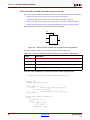
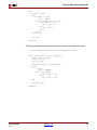
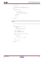
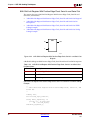
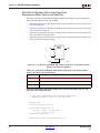
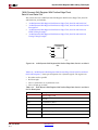
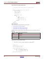
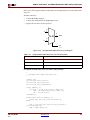
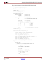
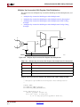
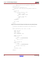
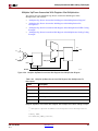
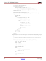
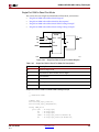
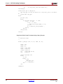
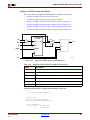
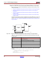
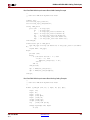
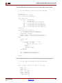
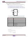
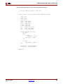
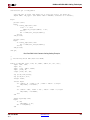
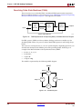
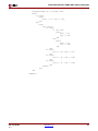
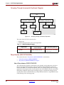
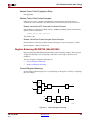
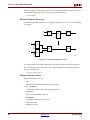
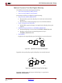
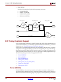
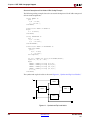
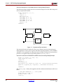
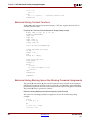
R
Structural Verilog Features
•
Signal
Corresponds to a wire between components
In Verilog, a component is represented by a design module. The module declaration
provides the external view of the component. It describes what can be seen from the
outside, including the component ports. The module body provides an internal view. It
describes the behavior or the structure of the component.
The connections between components are specified within component instantiation
statements. These statements specify an instance of a component occurring within another
component or the circuit. Each component instantiation statement is labeled with an
identifier. Besides naming a component declared in a local component declaration, a
component instantiation statement contains an association list (the parenthesized list) that
specifies which actual signals or ports are associated with which local ports of the
component declaration.
Verilog provides a large set of built-in logic gates which can be instantiated to build larger
logic circuits. The set of logical functions described by the built-in gates includes:
•
AND
•
OR
•
XOR
•
NAND
•
NOR
•
NOT
Structural Verilog Coding Examples
This section gives the following Structural Verilog coding examples:
•
“Building a Basic XOR Function Structural Verilog Coding Example”
•
“Structural Description of a Half Adder Structural Verilog Coding Example”
•
“Structural Instantiation of REGISTER and BUFG Structural Verilog Coding
Example”
Building a Basic XOR Function Structural Verilog Coding Example
Following is an example of building a basic XOR function of two single bit inputs a and b:
module build_xor (a, b, c);
input a, b;
output c;
wire c, a_not, b_not;
not a_inv (a_not, a);
not b_inv (b_not, b);
and a1 (x, a_not, b);
and a2 (y, b_not, a);
or out (c, x, y);
endmodule
Each instance of the built-in modules has a unique instantiation name such as:
XST User Guide
10.1
•
a_inv
•
b_inv
•
out
www.xilinx.com
513