1
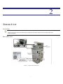
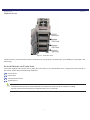
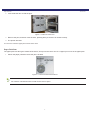
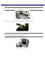
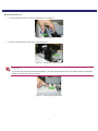
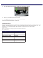
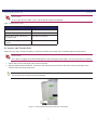
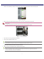
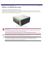
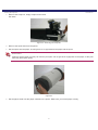
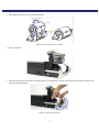
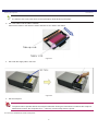
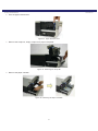
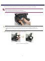
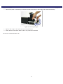
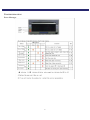
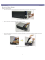
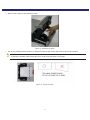
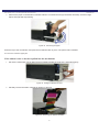
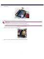
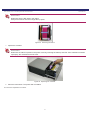
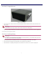
DRY M I N I L A B SYST E M
NLͲ2000
HardwareUserGuide
Version 1.0 2008.11.25
Acknowledgements
A CKNOWLEDGEMENTS
The information contained in this document represents the current view of Dai Nippon Printing Co.,Ltd. on the issues discussed as of the date of
publication. Because Dai Nippon Printing Co.,Ltd. must respond to changing market conditions, it should not be interpreted to be a commitment on the
part of Dai Nippon Printing Co.,Ltd., and Dai Nippon Printing Co.,Ltd. cannot guarantee the accuracy of any information presented after the date of
publication.
This document is for informational purposes only. Dai Nippon Printing Co.,Ltd. MAKES NO WARRANTIES, EXPRESSED OR IMPLIED, AS TO THE
INFORMATION IN THIS DOCUMENT.
Complying with all applicable copyright laws is the responsibility of the user. Without limiting the rights under copyright, no part of this document may be
reproduced, stored in or introduced into a retrieval system, or transmitted in any form or by any means (electronic, mechanical, photocopying, recording,
or otherwise), or for any purpose, without the express written permission of Dai Nippon Printing Co.,Ltd..
Dai Nippon Printing Co.,Ltd. may have patents, patent applications, trademarks, copyrights, or other intellectual property rights covering subject matter in
this document. Except as expressly provided in any written license agreement from Dai Nippon Printing Co.,Ltd., the furnishing of this document does not
give you any license to these patents, trademarks, copyrights, or other intellectual property.
ScanStation™, PrintMaster™, iStation™, PicViewer™, Photo Theater™, MyPhotoLab™, NexLab™, PixelWare™, LabServer™, One Touch Digital
Prints™ and One Touch Digital Printing™ are trademarks of DNP Photo Imaging America Corp.. The names of actual companies and products mentioned
herein may be the trademarks of their respective owners.
PrintRush™ is a trademark of Dai Nippon Printing Company LTD.
Dell® is a registered trademark of Dell Inc., pcAnywhere® is a registered trademark of Symantec Corporation, Kodak™ is a trademark of Eastman Kodak
Company, Epson Stylus® is a registered trademark of Seiko Epson Corporation, and Sony® is a registered trademark of Sony Electronics Corporation.
GO Software™, PC-Charge™, Win-Charge™ are trademarks of GO Software, Inc. IrDA® is a registered trademark of Infrared Data Association.
Bluetooth® is a registered trademark of the Bluetooth SIG, and Macromedia® and Flash® are registered trademarks of Macromedia, Inc. All other
trademarks are the property of their respective owners.
Dai Nippon Printing Co.,Ltd.
© 2000-2006 Dai Nippon Printing Co.,Ltd.. All rights reserved.
B EFORE YOU B EGIN
IMPORTANT SAFETY INSTRUCTIONS
Safety is paramount. These safety instructions are to protect you, your customer and your investment in the DNP Photo
Imaging America Corp. product line and for the overall public. The following bullet points apply to the safety instructions in
this manual:
Read all of these instructions before setting up, installing, and operating your system.
Follow all warnings, safety precautions, and notices for all procedures in this manual.
When in doubt, stop what you are doing and reassess the safety of the situation or procedure. Never continue with a
step or procedure when there is the slightest doubt regarding safety.
Save these instructions for future reference.
GENERAL SAFETY PRECAUTIONS
Never install or setup the system near water.
Never place the system on an unstable platform.
Never place the system near a heat source such as a heater or furnace.
Never perform any of these steps while wearing jewelry (rings, loose necklaces, bracelets, etc.), neckties or long
sleeve shirts. These items are conductors of electricity or may get caught in the unit and cause injury.
Never insert any foreign object into the system unit without powering the system OFF first.
Never block ventilation ports; allow plenty of room around the system for ventilation.
Never use water or liquid to extinguish a fire on the system unit.
Always protect the power cord from accidental kinks, cuts, and foot traffic.
Always operate this system from the correct type of grounded power source.
Always clean and maintain the system in the prescribed manner as instructed in this manual.
Always use this equipment in the specified manner as recommended by the manufacturer.
Failure to observe safety precautions voids your warranty and may cause damage to the unit and could result in
personal injury or death. Contact technical support at 1-877-388-1776 if:
The system is damaged due to fire or flood; or is otherwise unsafe to operate.
Any part of the system is dropped, cracked, or is not operating properly after performing cleaning and
maintenance.
You have any questions not answered in this manual.
i
GENERAL SAFETY PRECAUTIONS
Before You Begin
ii
Basic Maintenance
IMPORTANT SAFETY INSTRUCTIONS
GENERAL SAFETY PRECAUTIONS . . . . . . . . . . . . . . . . . . . . . . . . . . . . . . . . . . . . . . . . . . . . . . . . . . . . i
OVERVIEW
OVERVIEW . . . . . . . . . . . . . . . . . . . . . . . . . . . . . . . . . . . . . . . . . . . . . . . . . . . . . . . . . . . . . . . . . . . . . . . . . . 1
DOCUMENTATION CONVENTIONS . . . . . . . . . . . . . . . . . . . . . . . . . . . . . . . . . . . . . . . . . . . . . . . . . . . 1
Tower Unit
Tower Parts . . . . . . . . . . . . . . . . . . . . . . . . . . . . . . . . . . . . . . . . . . . . . . . . . . . . . . . . . . . . . . . . . . . . . . . . . . . . . . . . . . . . . . . . . 3
Doors and Covers . . . . . . . . . . . . . . . . . . . . . . . . . . . . . . . . . . . . . . . . . . . . . . . . . . . . . . . . . . . . . . . . . . . . . . . . . . . . . . . . . . . . 3
Inside the Tower . . . . . . . . . . . . . . . . . . . . . . . . . . . . . . . . . . . . . . . . . . . . . . . . . . . . . . . . . . . . . . . . . . . . . . . . . . . . . . . . . . . . . 4
SYSTEM ERRORS AND PAPER JAMS . . . . . . . . . . . . . . . . . . . . . . . . . . . . . . . . . . . . . . . . . . . . . . . . . . 4
Printer Errors . . . . . . . . . . . . . . . . . . . . . . . . . . . . . . . . . . . . . . . . . . . . . . . . . . . . . . . . . . . . . . . . . . . . . . . . . . . . . . . . . . . . . . . 5
Paper Jams . . . . . . . . . . . . . . . . . . . . . . . . . . . . . . . . . . . . . . . . . . . . . . . . . . . . . . . . . . . . . . . . . . . . . . . . . . . . . . . . . . . . . . . . . . 5
Tower Door Jam . . . . . . . . . . . . . . . . . . . . . . . . . . . . . . . . . . . . . . . . . . . . . . . . . . . . . . . . . . . . . . . . . . . . . . . . . . . . . . . . . . . . . 5
Paper Path Jam . . . . . . . . . . . . . . . . . . . . . . . . . . . . . . . . . . . . . . . . . . . . . . . . . . . . . . . . . . . . . . . . . . . . . . . . . . . . . . . . . . . . . . 6
.................................................................................................... 7
Back Printer Jams . . . . . . . . . . . . . . . . . . . . . . . . . . . . . . . . . . . . . . . . . . . . . . . . . . . . . . . . . . . . . . . . . . . . . . . . . . . . . . . . . . . . 7
Back Printer Door A . . . . . . . . . . . . . . . . . . . . . . . . . . . . . . . . . . . . . . . . . . . . . . . . . . . . . . . . . . . . . . . . . . . . . . . . . . . . . . . . . . 9
Back Printer Door B . . . . . . . . . . . . . . . . . . . . . . . . . . . . . . . . . . . . . . . . . . . . . . . . . . . . . . . . . . . . . . . . . . . . . . . . . . . . . . . . . 10
Back Printer Door C . . . . . . . . . . . . . . . . . . . . . . . . . . . . . . . . . . . . . . . . . . . . . . . . . . . . . . . . . . . . . . . . . . . . . . . . . . . . . . . . . 10
Replacing the Conveyor Unit . . . . . . . . . . . . . . . . . . . . . . . . . . . . . . . . . . . . . . . . . . . . . . . . . . . . . . . . . . . . . . . . . . . . . . . . . . 10
Back Printer Door D . . . . . . . . . . . . . . . . . . . . . . . . . . . . . . . . . . . . . . . . . . . . . . . . . . . . . . . . . . . . . . . . . . . . . . . . . . . . . . . . . 10
Communication Errors . . . . . . . . . . . . . . . . . . . . . . . . . . . . . . . . . . . . . . . . . . . . . . . . . . . . . . . . . . . . . . . . . . . . . . . . . . . . . . . 11
System Errors . . . . . . . . . . . . . . . . . . . . . . . . . . . . . . . . . . . . . . . . . . . . . . . . . . . . . . . . . . . . . . . . . . . . . . . . . . . . . . . . . . . . . . 11
CLEANING THE TOWER UNIT . . . . . . . . . . . . . . . . . . . . . . . . . . . . . . . . . . . . . . . . . . . . . . . . . . . . . . . 12
Printer Basics
GENERAL MAINTENANCE . . . . . . . . . . . . . . . . . . . . . . . . . . . . . . . . . . . . . . . . . . . . . . . . . . . . . . . . . . 15
DS40 and DS80 Printers
Distinguishing Your DS40 and DS80 Printer Model . . . . . . . . . . . . . . . . . . . . . . . . . . . . . . . . . . . . . . . . . . . . . . . . . . . . . . . 16
Installing Media . . . . . . . . . . . . . . . . . . . . . . . . . . . . . . . . . . . . . . . . . . . . . . . . . . . . . . . . . . . . . . . . . . . . . . 17
DS40 and DS80 Printers . . . . . . . . . . . . . . . . . . . . . . . . . . . . . . . . . . . . . . . . . . . . . . . . . . . . . . . . . . . . . . . . . . . . . . . . . . . . . . 17
Installing the Paper Roll . . . . . . . . . . . . . . . . . . . . . . . . . . . . . . . . . . . . . . . . . . . . . . . . . . . . . . . . . . . . . . . 17
Maintaining the Printers . . . . . . . . . . . . . . . . . . . . . . . . . . . . . . . . . . . . . . . . . . . . . . . . . . . . . . . . . . . . . . . 21
Emptying the Paper Scrap Bin . . . . . . . . . . . . . . . . . . . . . . . . . . . . . . . . . . . . . . . . . . . . . . . . . . . . . . . . . . 21
Cleaning the Ventilation Area . . . . . . . . . . . . . . . . . . . . . . . . . . . . . . . . . . . . . . . . . . . . . . . . . . . . . . . . . . 22
Cleaning the Platen Roller . . . . . . . . . . . . . . . . . . . . . . . . . . . . . . . . . . . . . . . . . . . . . . . . . . . . . . . . . . . . . 23
Troubleshooting . . . . . . . . . . . . . . . . . . . . . . . . . . . . . . . . . . . . . . . . . . . . . . . . . . . . . . . . . . . . . . . . . . . . . . 27
Error Messages . . . . . . . . . . . . . . . . . . . . . . . . . . . . . . . . . . . . . . . . . . . . . . . . . . . . . . . . . . . . . . . . . . . . . . . . . . . . . . . . . . . . . 27
Basic Maintenance
Resolving Media Errors . . . . . . . . . . . . . . . . . . . . . . . . . . . . . . . . . . . . . . . . . . . . . . . . . . . . . . . . . . . . . . . 28
If there is a Paper Jam:. . . . . . . . . . . . . . . . . . . . . . . . . . . . . . . . . . . . . . . . . . . . . . . . . . . . . . . . . . . . . . . . . . . . . . . . . . . . . . .
If the ribbon is torn or has been pulled into the mechanism: . . . . . . . . . . . . . . . . . . . . . . . . . . . . . . . . . . . . . . . . . . . . . . . .
If the Printer is Stopped Mid-action:. . . . . . . . . . . . . . . . . . . . . . . . . . . . . . . . . . . . . . . . . . . . . . . . . . . . . . . . . . . . . . . . . . . .
If the Power is Cut During Printing: . . . . . . . . . . . . . . . . . . . . . . . . . . . . . . . . . . . . . . . . . . . . . . . . . . . . . . . . . . . . . . . . . . . .
28
30
33
33
1
OVERVIEW
As part of maintaining your system, you need to clean equipment and perform periodic adjustments and enhancements to
the system.
OVERVIEW
The following are the most common equipment procedures and tasks. They are provided here merely as a convenience.
These procedures do not replace those in the manuals that accompanied the equipment.
Note
Due to the wide variety of configurations and options available with the system, this book may
include information on equipment that did not come with your system.
Use the following procedures to perform routine maintenance and updates to your system. If you need further assistance,
contact Technical Support at 1-877-388-1776.
DOCUMENTATION CONVENTIONS
When using this Basic Maintenance, several symbols and headings are repeated throughout. The following is an
explanation of these symbols and headings:
Text Elements
equipment.
Attention – This symbol signifies important information concerning safety when working with the
Failure to comply with an Attention statement can cause injury or harm or cause damage to the system.
Note – This symbol highlights convenient or useful instructions.
Text Treatments
Bold Text – Indicates items you select, such as buttons and menu entries.
Italic Text – Indicates variable test or placeholders for information, such as user names and directory paths. When
entering directory paths and so forth, the word in italics should not be typed, but should be replace by the appropriate
text.
Italic text also introduces new words, and is occasionally used for emphasis in text.
Monospace – Distinguishes information that is displayed on the screen as well as the text that you should enter.
1
DOCUMENTATION CONVENTIONS
Overview
SMALL CAPS – Logic values, Boolean operations, and particular keys on the keyboard. When used to indicate on the
keyboard, a plus sign (+) between two keys indicates you should hold down the first key while pressing the second. A
comma (,) between two keys indicates you should release the first key before pressing the second key.
2
2
TOWER UNIT
Tower Parts
Note
These covers and doors are referenced in paper jam and other system errors. Please make note
of their locations.
Doors and Covers
Figure 1. Tower Doors and Covers
3
Inside the Tower
Tower Unit
Inside the Tower
Figure 2. Inside the Tower
Inside the tower, you will find four printers: three DS40 (4 x 6) printers in the three bays, and a DS80 (8 x 12) printer in the
bottom bay.
SYSTEM ERRORS AND PAPER JAMS
If the tower experiences a printer error, a paper jam in the tower, or a communication error, a system error will come up on
the screen. Errors fall into the following categories:
Printer Errors
Paper Jams
Communication Errors
System Errors
Note
The printers will need to cool off periodically. The system will notify you when a printer is cooling,
and the printer will resume printing in approximately 10 to 15 seconds.
4
Printer Errors
Tower Unit
Printer Errors
Because the printers are routed through the tower, all printer errors will appear on the main screen. When the error
appears, the system will tell you which printer is experiencing the problem, and what to do to fix it. The most common errors
are listed in the table below:
Table 1: Printer Errors
System Message
Solution
End of Paper
Insert new roll
End of Ribbon
Insert new ribbon
Cover is Open
Close front of printer
Paper Jam in Printer
Clear paper jam
Printer Ribbon Jam in Printer
Clear ribbon jam
Ribbon Tension Error
Reset ribbon
Scrap Box is Missing
Replace scrap box
USB Connection Failed
Check USB connection to printer.
Paper Jams
Most error messages deal with printer jams and media problems. Once the print has exited the printer, it can become
jammed in three main areas:
the tower door
the paper path
the back printer
Attention
The tower will not allow another print to be sent through the system if there is a paper jam in any of these areas.
Tower Door Jam
If a print becomes jammed in the tower door:
1. Open the tower door by pressing in on the handle, and then pulling the door towards you.
Figure 3. Opening the Tower Door
System Message Solution
5
Paper Path Jam
Tower Unit
2. Look inside the door to find the print.
Figure 4. Inside the Tower Door
3. Remove the print, and then close the door, pressing firmly to ensure it is closed correctly.
4. The printer will reset.
You have now cleared a paper jam from the tower doors.
Paper Path Jam
The paper path runs along the outside of the doors, and up into the corner unit. If a a paper jam occurs in the paper path:
1. Unlock the paper path door where the jam is located.
Figure 5. Locked and Unlocked Positions
Note
You need to unlock both locks in order for the door to open.
6
Tower Unit
2. Open the paper path door.
Figure 6. Paper Path Door Opened
3. Remove the jammed print.
4. Close the Paper Path Door and re-lock the door, holding the door shut with slight pressure.
Attention
The printer will not send another print if there is a print in the paper path.
The printer will not print if the paper path door is open.
You have now cleared a paper jam from the paper path.
Back Printer Jams
The back printer is used to print photo information on the white (unprinted) side of the print. All prints must pass through the
back printer unit.
1. Disconnect the conveyor belt cable from the unit.
Note
Pull lightly on the metal ring on the cable to unlock and remove it from the unit.
Figure 7. Back Printer Conveyor Cable
2. To access the back printer unit, push the buttons located on either side of the top conveyor so that they are unlocked.
7
Back Printer Jams
Tower Unit
Note
When the buttons are locked, they are flush with the unit, and the back printer cannot be removed.
Figure 8. Back Printer Release Button
3. Pull the conveyor up and away to access the back printer doors. Set the conveyor aside.
Figure 9. Removing the Back Printer Conveyor
Note
The conveyor has parts that stick out from the bottom of the unit.
Take care when setting it down on a clean, flat surface.
4. Using the illustration below, find the area where the print is jammed.
Figure 10. Back Printer Doors
8
Back Printer Door A
Tower Unit
Back Printer Door A
5. To open back printer door A, press on the blue lever indicated.
Figure 11. Back Printer Door A Lever
6. The door will swing up. Look inside for jammed prints.
Figure 12. Checking for Jammed Prints
Attention
If you open the door fully to the locked position, you must press the blue lever on the side of the unit, indicated
below, to release the door and close it.
Figure 13. Unlocking Back Printer Door
9
Back Printer Door B
Tower Unit
Back Printer Door B
7. Open back printer door B by pulling up on the handle. The door will open.
Figure 14. Opening Back Printer Door B
8. Remove any jammed prints.
9. Close the door, making sure it is secure.
Back Printer Door C
10. Open back printer door C by pulling up on the tab at the bottom of the door.
Figure 15. Opening Back Printer Door C
11. Remove any jammed prints.
12. Close the door, making sure it is secure.
Replacing the Conveyor Unit
13. Place the conveyor unit on the back printer, lining up the guides and buttons.
14. Depress both buttons to lock them. They will remain flush with the unit when locked.
15. Reconnect the cable, take care to align the arrow on top of the plug.
Back Printer Door D
16. You do not need to remove the conveyor unit to remove paper jams from back printer door D.
10
Communication Errors
Tower Unit
17. Open back printer door D by pulling the top roller gently. The rollers will stay open.
Figure 16. Opening Back Printer Door D
18. Remove any prints that may be jammed in the unit.
19. Press lightly on top of the door to close. The door will lock in place.
You have now cleared the back printer from any paper jams.
Communication Errors
The most common communication error happens when a USB cable has been disconnected, or is not fully inserted into the
connection. Check both ends of the cable (when able) and reseat them if necessary. This should resolve the issue. If the
errors reoccur, or do not resolve when the cable is reseated, call Technical Support at 1-888-749-3587.
System Errors
All other errors fall into the category of system errors, and are listed below:
Table 2: System Errors
System Message
Solution
Head Voltage Error
Reset Printer (turn off/on)
Head Position Error
Reset Printer
Power Supply Fan Stopped
Reset Printer
Cutter Error
Reset Printer
Pinch Roller Position Error
Reset Printer
Abnormal Head Temperature
Allow printer to cool, reset printer.
RFID Module Error
Check printer media, reset Printer.
If any of these system errors persists, call Technical Support.
11
CLEANING THE TOWER UNIT
Tower Unit
Attention
If any of the errors in Table 3 occur, call Technical Support immediately.
Table 3: System Errors (cont.)
System Message
Solution
System Error
Call Technical Support
Firmware Error
Call Technical Support
Device Error while Transferring
Firmware Data
Call Technical Support
Error while Sending Firmware
Update
Call Technical Support
CLEANING THE TOWER UNIT
About once a month, it will be necessary to clean the air filters in the tower unit to maintain optimum performance.
Attention
If the filter is clogged, the internal temperature of the housing becomes higher, and can cause errors in printing.
1. Power down the unit and unplug the unit from the wall.
2. Using a phillips head screwdriver, remove the wire housing from the back of the tower unit by loosening the two
screws on the side of the tower unit.
System Message Solution
Note
You do not have to remove the screws entirely.
Figure 17. Removing the Screws from the Side of the Printer
12
CLEANING THE TOWER UNIT
Tower Unit
3. Pull the cover towards you until you can remove the panel by sliding the tabs from the back of the printer.
Figure 18. Panel Tabs
4. Remove the top and bottom panels from the back of the tower, exposing the fan units inside.
Attention
The sides of the panels may be sharp. Take care when removing the back panels.
Figure 19. Back Panel Removed
5. Pop off the fan cover by pulling from the bottom.
6. Vacuum the fan blades and filter cover.
Note
The air filters are very thin. Take care not to damage the air filters with the vacuum.
7. Replace the fan when you are done, move to the next fan.
8. When you have vacuumed all the fans, replace the back panels.
Note
There is no particular order to replacing the back panels, but make sure you place the panel with
the holes for the wire cover box on the bottom.
13
CLEANING THE TOWER UNIT
Tower Unit
Attention
Do not pinch or cut the wires when replacing the panel
9. Replace the wire cover by first inserting the tabs into the holes in the back panel, and then moving the box so that the
indentions for the screws line up with the screws.
10. Make sure no wires are being pinched by the box. Tighten the screws.
11. Plug the unit in and power the unit back on.
You have now cleaned the air filters on the tower unit.
14
3
PRINTER BASICS
This chapter provides you with basic information on how to maintain and troubleshoot your printer.
GENERAL MAINTENANCE
Part of the normal maintenance cycle for printers includes removing dust buildup from the printer vents. This is done to free
ventilation holes from dust and foreign matter and to improve printer longevity. The following instructions are written in a
generic fashion to include all printers for the systems:
1. Power OFF the system at the main power source.
2. Using a small hand vacuum with a non-metallic extension and nozzle, vacuum all of the printers ventilation ports.
3. Vacuum the base of the system and external ventilation ports.
4. Power ON the system and remaining components.
You have now performed basic maintenance on the printer.
15
Distinguishing Your DS40 and DS80 Printer Model
Printer Basics
DS40 AND DS80 PRINTERS
Distinguishing Your DS40 and DS80 Printer Model
The DS series are versatile photo printers for use in photo labs by professional photographers, or in other commercial
situations which demand high speed and exceptional quality. Other information on the printers can be found in the printer’s
field service manual or your system’s documentation suite.
Figure 20. The DS40 or DS80 printer
Attention
Prior to moving the printer, the ink ribbon cassette and paper roll should be removed from the printer. Always
take care when lifting the printer so as not to cause physical injury.
When reinstalling, check that the ribbon and paper are properly positioned before resuming printing. If either is
positioned incorrectly, paper jams, print position errors, or other unexpected problems can occur.
The DS40 and DS80 printers are quite similar. The instructions written for one will work for the other. The main difference is
in paper size; DS40 printers print 4x6 size prints, and DS80 printers print 8x12 size prints.
Note
If your printer is configured for use in a tower system, the printer will have small rubber feet. These
feet are essential to aligning the output for the printer with the tower conveyor system and keeping
the printer from moving inside the unit. Do not remove the feet.
16
Installing Media
Printer Basics
INSTALLING MEDIA
DS40 and DS80 Printers
Use the following procedures with your DS40 and DS80:
INSTALLING THE PAPER ROLL
Note
Its is a good idea to check that there is enough paper in the printer to meet anticipated demand.
Avoid touching the surface of the paper. Excessive fingerprints or smudges can lead to poor print
quality.
1. Pull out the mechanism unit by lifting the blue handle beneath the scrap box, and pulling gently.
Figure 21. Pulling the Mechanism Unit
2. Free the paper release lever.
Figure 22. Paper Release Lever
17
Installing the Paper Roll
Printer Basics
3. Remove the scrap box, empty scraps into the trash.
Set aside.
Figure 23. Removing the Scrap Box
4. Remove the spool ends from the printer.
5. Set the spools into the paper, ensuring there is no gap between the paper and the spool.
Attention
Failure to set the paper correctly can result in print jams. Do not get dirt or fingerprints on the paper, as they will
adversely affect print quality.
Figure 24.
6. Set the paper holder into the paper cassette in the printer. Make sure you set the paper in firmly.
18
Installing the Paper Roll
Printer Basics
7. Set the paper so that it is in the direction shown.
Figure 25. inserting paper into cassette
8. Remove the seal
9. Advance the paper in the direction indicated. When it is inserted far enough, the buzzer will beep and the paper LED
(orange) will stop blinking.
Figure 26. Advancing the paper
19
Installing the Paper Roll
Printer Basics
Note
It is easier to set if you press down on the spool lightly while advancing the paper.
10. Set a new ribbon into the ribbon cassette.
Advance the ribbon in the direction shown and take up any slack in the ribbon.
Figure 27.
11. Set it with the supply side in the front.
Figure 28.
12. Set the scrap box.
Attention
The printer will not operate without the scrap box attached. Closing the mechanism unit without the scrap box
attached will cause a “No Scrap Box Error.” Clean any excess scraps from the printer.
You have now installed the media in the printer.
20
Maintaining the Printers
Printer Basics
MAINTAINING THE PRINTERS
EMPTYING THE PAPER SCRAP BIN
Attention
When the scrap box is removed, do not touch the cutter, as there is a danger of injury.
Before replacing the printer media, remove the paper’s scrap bin.
1. Pull out the mechanism unit by lifting the blue handle beneath the scrap box, and pulling gently.
Figure 29. Pulling the Mechanism Unit
2. Free the paper release lever.
Figure 30. Paper Release Lever
3. Remove the scrap box, empty scraps into a proper receptacle...
21
Cleaning the Ventilation Area
Printer Basics
4. Replace the scrap bin.
Attention
The printer will not operate without the scrap box.
Closing the mechanism unit without the scrap box attached will cause a “No Scrap Box Error,” and the red error
LED will blink.
5. Close the top of the mechanism unit, and push unit back in place.
Note
Closing the mechanism unit starts initialization (4 blank sheets are fed out).
You have now performed basic maintenance on the printer.
CLEANING THE VENTILATION AREA
Periodically, you should check the ventilation or exhaust for the printer, as it can become clogged with dust.
Attention
If the ventilation for the printer becomes clogged or blocked, the inside temperature of the housing becomes
higher and can cause the thermal head to overheat.
When the thermal head overheats, printing halts and the power LED will blink. Printing resumes automatically
when the head temperature cools. The thermal head can also overheat due to inputting continuous high-power
such as printing all black images.
1. Turn the printer OFF.
Access the rear of the printer.
Note
You may need to unplug the power or network cables to completely access the back of the printer.
If you will have to disconnect power, make sure you power down the unit previous to unplugging
the unit.
22
Cleaning the Platen Roller
Printer Basics
2. The exhaust for the printer is located near the top of the back plate, as indicated in the illustration below:
Figure 31. Ventilation Port
3. Wipe the dust from the unit using a cloth designed for dusting electronics, or use canned air to blow the dust from the
back of the unit.
4. Replace any cables you may have had to disconnect to access the back of the printer, and put the printer back in
place.
5. Power the unit ON.
You have now cleaned the dust from the ventilation unit.
CLEANING THE PLATEN ROLLER
If any impressions appear regularly in the same place on the prints, on either the front or back, you will need to clean the
platen roller. There could be powder, paper scraps, or other debris stuck to the roller.
1. Pull out the mechanism unit by lifting the blue handle beneath the scrap box, and pulling gently.
Figure 32. Pulling the Mechanism Unit
23
Cleaning the Platen Roller
Printer Basics
2. Free the paper release lever.
Figure 33. Paper Release Lever
3. Remove the scrap box, empty scraps into a proper receptacle...
Figure 34. Removing the Scrap Bin
4. Remove the paper cassette.
Figure 35. Removing the Paper Cassette
24
Cleaning the Platen Roller
Printer Basics
5. Using the alcohol pads provided, wipe any dirt off the platen roller while rotating the roller slightly.
Attention
Only use the alcohol pads provided in the cleaning kit.
Take care to avoid injury and damage due to the sharp edges.
Note
If there is debris that will not come off using the alcohol pad, run the sandpaper provided in the
cleaning kit over the area lightly until the debris is removed. Clean the area again with an alcohol
pad.
6. Replace the paper cassette. Make sure the casette is firmly seated.
Figure 36. replacing the paper cassette.
25
Cleaning the Platen Roller
Printer Basics
7. Advance the paper in the direction indicated until the buzzer beeps, and orange Paper LED stops blinking.
Figure 37. Advancing the paper
8. Replace the scrap bin and close the top of the mechanism.
9. Gently slide the mechanism back in place. The printer will re-initialize.
You have now cleaned the platen roller.
26
Troubleshooting
Printer Basics
TROUBLESHOOTING
Error Messages
27
Resolving Media Errors
Printer Basics
RESOLVING MEDIA ERRORS
If there is a Paper Jam:
1. Pull out the mechanism unit by lifting the blue handle beneath the scrap box, and pulling gently.
Figure 38. Pulling the Mechanism Unit
2. Remove the ribbon cassette by pulling the cassette up and out.
Figure 39. Removing the Ribbon Cassette
3. Pull any paper remaining in the printer in the direction indicated, and cut off any wrinkled or partially printed areas
evenly with scissors.
Figure 40. Pulling and Trimming the Paper
28
If there is a Paper Jam:
Printer Basics
4. Remove the scrap box and rewind the paper.
Figure 41. Rewinding the Paper
5. Cut off any partially printed, wrinkled, or otherwise inferior paper evenly with scissors and reset the paper.
Note
If wrinkles or partially printed areas are left, it could cause the paper to jam again.
Figure 42. Cutting the Paper
29
If the ribbon is torn or has been pulled into the mechanism:
Printer Basics
6. Advance the paper in the direction indicated. When it is inserted far enough the buzzer will beep, and the orange
Paper LED light will stop blinking.
Figure 43. Advancing the paper
Close the top of the mechanism, and push the mechanism back in place. The printer will re-initialize.
You have now cleared a paper jam.
If the ribbon is torn or has been pulled into the mechanism:
1. Pull out the mechanism unit by lifting the blue handle beneath the scrap box, and pulling gently.
Figure 44. Pulling the Mechanism Unit
2. Carefully remove the ribbon cassette by pulling up and out.
Figure 45. Removing the Ribbon Cassette
30
If the ribbon is torn or has been pulled into the mechanism:
Printer Basics
3. Cut the ribbon.
Figure 46. Cutting the ribbon
4. Carefully remove the remaining ribbon from inside the mechanism.
Attention
If the ribbon is torn or left in the printer, it could affect print quality.
You may need to clean the platen roller (see Cleaning the Platen Roller).
Figure 47. Removing the Ribbon
5. Reattach the ribbon using clear or cellophane tape.
Figure 48. Placing the tape
6. Advance the ribbon several times as shown, until the tape is out of sight.
31
If the ribbon is torn or has been pulled into the mechanism:
Printer Basics
Attention
Make sure there is NO slack in the ribbon.
Always wind ribbon onto the orange take-up spool.
Figure 49. Advancing the ribbon
7. replace the cassette.
Attention
Make sure the ribbon is placed in the printer correctly, inserting the take-up side first. If the cassette is inserted
improperly, the mechanism will not close.
Figure 50. Replacing the Cassette.
8. Close the mechanism. The printer will re-initialize.
You have now repaired a torn ribbon.
32
If the Printer is Stopped Mid-action:
Printer Basics
If the Printer is Stopped Mid-action:
Figure 51. Printer Stopped
1. Turn the power OFF, and then back ON. The jammed paper should be released, and the cutter should return to its
ready position
Attention
The mechanism will not open until the cutter has been returned to the ready position.
2. Remove any partially printed paper from inside the mechanism, following the instructions for “if there is a paper jam.”
You have reset a printer stopped in mid-action.
If the Power is Cut During Printing:
Attention
If the power is cut during printing, the mechanism unit cannot be pulled out. The mechanism will not open until
the cutter has been returned to the ready position.
1. Turn the power back ON. The partial print will be cut into scrap lengths and discarded in the scrap bin.
2. Once the cutter has returned to the ready position, the mechanism can be pulled out.
3. Check that there is no partially printed paper in the mechanism unit. If there is, see: “if there is a paper jam.”
33
If the Power is Cut During Printing:
Printer Basics
34