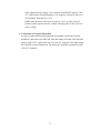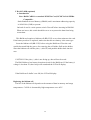
1
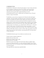
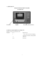
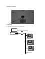
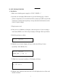
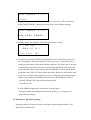
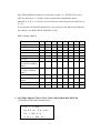
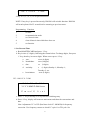
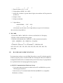
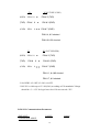
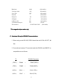
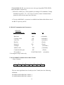
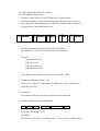
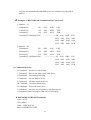
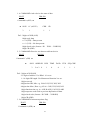
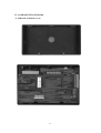
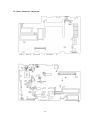
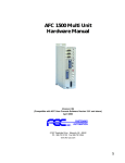
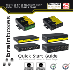
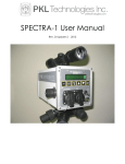
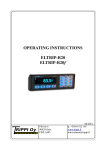
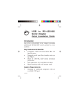
DM-280
Time Recording Terminal
User’s Guide
Version 1.0
July, 1999
1
DM-280 User’s Manual
I.
A.
B.
C.
D.
II.
A.
B.
C.
Table of Contents
Introduction
Page
1
Appearance
Physical Description
Back of Chassis
RS-485 Configuration Diagram
2
2
3
3
Set-up Procedures
3
Installation
Parameters: Dip Switch settings
Master card : Setting Function
3
5
6
D.
E.
F.
Temporary Card
Data Print-Out
ID CARD
11
12
12
III.
RS-232/RS-485 Communications
13
A.
B.
C.
D.
E.
F.
G.
H.
I.
IV.
A.
B.
C.
RS-232 Hardware Set-up
Rs-232 Communication Parameters
RS-485 Hardware Set-up
RS-485 Communications Parameters
Communication Data Format
Examples of Conversions
Command Overview
RS-232/RS-485 Command Codes
Control flowchart
13
14
14
15
15
16
17
17
21
23
Component of of DM280
Underside of Bottom Cover
Chassis Mounted Components
Connection of External Music/bell
23
24
27
V.
RAM Card (optional)
28
A.
Introduction
28
29
VI . TCP/IP CARD (optional)
2
I. INSTRODUCTION
The DM-280 OA Timeclock records and sends employees’ entry/exit times and status
to a host computer for further processing. This eliminate errors in manual data
input/calculations and the redundancy of re-copying timecards. When used in
conjunction with a payroll software application package, the entire
time/attendance/payroll system is combined into one automatic process. Time and
monetary savings are immediate.
The DM-280 is a state-of-the-art computerized OA Timeclock with multi-lingual
capabilities. This unit introduces the RAM card option which allows the DM-280 to
be used as a stand-alone unit with an off-line capacity up to10,000 records. RAM
cards are collected from each unit periodically and the data downloaded to the host
computer. This avoids the costly cable installation charges and allows great flexibility.
The DM-280 can use a DC12V power source (like an auto cigarette lighter) and be
used where there is no electricity. (e.g. construction sites, field work, etc..) It can also
use RS-232/485 interfaces. The RS-485 interface allows networkability—up to 63
units can be connected to one host on the same line. This is ideal for factories or large
buildings with multiple entrances. On-line or off-line, hard copy printouts of time and
status of entry/exit can be made locally by connecting with the SP-190 Audit Printer
or other type printers.
The DM-280 offers three types of user interfaces to suit the user need.
The three options available for display are:
DM-280 with a proximity reader
DM-280 with a magnetic striper reader
DM-280 with an IC card reader
DM-280 can connect with a larger 64x128 dot matrix display for graphic images
necessary in Chinese and Japanese or in other non-Roman alphabets such as Arabic,
Russian, Korean, Thai, etc. It can also be used for displaying mathematical symbols or
user defined graphics.
This manual has been written for the model DM-280P.
3
A. APPEARANCE
DM280 WITH PROXIMITY READER
LCD DISPLAY
Power led
Keypad
Proximity reader(Antenna)
B. PHYSICAL DESCRIPTION OF DM-272T
Display: 8 lines of 16 characters each.
Keypad:
0- -9
Numeric keys
1
‘1’ key is also used when changing
parameters in master card operation
#
Enter key
reset
Reset key
4
C.BACK OF CHASSIS
Wiring outlet
D. RS-485 CONFIGURATION DIAGRAMS
Saho
RS-232-RS485 CONVETER
Address: 01
Address: 02
Address:03
Address: 04 etc..
5
II. SET-UP PROCEDURES
A. Installation
1. Make sure switching power supply is 12V DC, INNER “+”
2. Open the case and adjust DIP switches as per the following page. Connect
printer (if required) to J5 on main board. Place jumper-pin (SW2) top on both
connectors to initiate back-up battery to keep data and clock functions in the
event of a power outage.
3. Plug in power-cord.
4. If the power is in DM280, will begin a cold start process. If you are doing a
warm start (DSW2 set to ON in step 2) display will begin from step 8 below.
5. DM-280 performs a selftest .
Self
test
...
6. If RAM is out of order, display will say so and unit will beep 3 times
repeatedly. Check RAM (U4).
Self
test
RAM(U4)
...
Fail...
7. If DM-280 is in normal condition, LCD display will show
Self
No
test
...
Error
8. If RAM card is inserted in the unit, the LCD will display the size of the card
which is inserted.
6
Saho
DM280
V1.0
M1024
9. The unit will next run a RAM card test. If there is an error, LCD will indicate
“RAM CARD ERROR”, otherwise the unit goes to next display massage.
Saho
RAM
DM280
CARD
V1.0
ERROR
10. Display shows data and time. This indicates the unit is ready.
***
DM-280
***
1999/07/01
Function
〔A〕
11. If a card is presented to DM280, the ID number of the card will be shown on
the LCD Display, and stored in buffer with a long ‘beep’. At the same time, if
connected, the printer will print the number and time. If a RAM card is inserted
in the unit the data will be first sent to and stored in the RAM card. If the card
is full, the data will be set to and stored in the DM280’s memory buffer. When
the RAM card is full, LCD shows status and beeps. Remove it and replace with
a new one (see RAM card section) Or retrieve it through serial communication.
If there is remaining in the DM280’s buffer, the LCD will Display “MOVE
DATA TO RAMCAR” and will download the data
to the New card.
12. If the DM280 sounds three short beeps, it means either:
Wrong operation has happened upon card presenting, e.g. wrong key was
pressed before sliding.
B. Parameters: Dip Switch settings
Set the parameters to suit your needs via the dip switches and the Master Card
functions described below.
7
Note: When DM280 is turned on, it will start at status “A”. If DSW1 #6 is set to
OFF, one must press “#” (Enter) on the keypad before changing the status
manually to A, B, C, or D. If it is set ON, then one need only press the status key (1,
2, 3, 4).
To set hardware for RS-485 transmission, you need to use the Master card function
2(see below). Set DATA BIT to 8,PARITY to NO .
DSW1 settings (DSW1)
Situation
2
3
#1
Digit address
Digit address
RS-232
RS-485
#2
#3
#4
#5
#6
#7
ON
OFF
OFF ON OFF
ON OFF ON
Send signal to open door
Doesn’t send signal to
Open door
ON
OFF
Requires pressing ‘#’
Key before changing
Status
Doesn’t need pressing
‘#’ before changing
status
Adds CR to printer
OFF
ON
ON
Doesn’t add CR to
printer
Printer ON
OFF
ON
Printer OFF
OFF
C. MASTERCARD-SETTING FUNCTIONS FROM DM-280S KEYPAD
1. Read MASTERCARD, display shows:
1.Set
timer
2.Update
3.Set
#8
Param.
Music
4.Clear
Music
8
5.Set
Func
time
2. Key in 1 (2, 3, 4, 5 ) to do special function.
NOTE: If any key is pressed incorrectly, DM-280 will exit this function. DM-280
will scan keyboard for 25 seconds before returning to previous menu.
Programming
Function
1
set time
2
set transmission mode
3
set 30 music time
4
clear all music time which have been set
5
set function
1. Set Current Time
a. Read MASTERCARD and press ‘1’ key.
b. Key in time (13 digits), following the format below. To change digits, first press
‘1’ key, then key in correct digits. When correct press ‘#’ key.
a.
year:
xxxx (4 digits)
b.
month/date:
xxxx (4 digits)
c.
date:
xx
(2 digits)
d.
weekday:
x
(1 digits) Sunday=1; Monday=1;
Tuesday=2; etc.
e.
hour/minute:
xxxx (4 digits)
EG.: 1999 12 31 5 1200
1999123151230
YYYYMMDDWHHmm
Press〔1〕first
c. Press “1” key to modify or re-keyin before finishing entry.
d. Press ‘#’ key, display will return to main menu and show the current time and
date.
Note: Adjustment VC1 of U2 (Real time clock IC: M6242B) for frequency
correction. Use frequency counter to check IC’s pin #1 or TP1 pole. Set
9
frequency to 1.000 Hz.
2. Set Transmission Mode
a. Read MASTERCARD and press ’2’ key.
b. Display indicates that the transmission mode is RS-485 (see above for DSW1
settings ). To change this mode, press ‘1’ key and unit will cycle through 232
and 485. When it reaches the desired mode press ‘#’ key. (RS-485=CR-ON;
Databit-8; Parity-NO.)
RS-
485
c. Display next indicates the baud rate = 9600, press ‘1’ key to select the baud
rate 9600, 4800, 2400, 1200. When correct press the ‘#’ key.
Baud
Rate
RS-
9600
485
d. Display next indicates the carriage return is ON. This means record data is
attached with Carriage Return (0DH) when data is uploaded. If Carriage
Return is not required, press ‘1’ key. When correct press the ‘#’ key.
CR
Baud
ON
Rate
RS-
9600
485
e. Display will now indicate all data attached with LF code (0AH). If line Feed
is not required, press ‘1’ key. When correct press ‘#’ key.
Line
Feed
CR
Baud
RS-
ON
ON
Rate
9600
485
f. Display will next show data bit status. As this is fixed, press ‘#’ key to
10
continue.
Data
Bit
Line
Feed
8
ON
CR
ON
Baud
Rate
9600
RS-
485
g. Display will next show the parity status. If parity is not require, press ‘1’ key .
Press ‘#’ key to continue.
Parity
Data
Bit
Line
Feed
CR
NO
8
ON
ON
Baud
Rate
RS-
9600
485
h. Display will now show the ID length is 8 digits . Press ‘1’ key and key in 2
digits to change the length of ID number. The length of ID number can be
from 1 to 16. When correct press the ‘#’ key.
Id
length
Parity
Data
Bit
Line
Feed
CR
Baud
RS-
**
08
NO
8
ON
ON
Rate
9600
485
If buffer already had data present, this function is disabled and user may not
modify it.
i. Display will now show the address code is 001. Press ‘1’ key and key in 3
digits to modify the address code. When correct press ‘#’ key.
11
Addr
Id
Code
001
length
08
Parity
Data
Bit
Line
Feed
CR
8
ON
ON
Baud
**
NO
Rate
9600
If buffer already had data present, this function is disable and user may not
modify it.
j. Display will next show the file number found on valid cards. To change the
file number press ‘1’ key and modify the digits. Press ‘#’ key when finished.
1234567890123456
File
Id
NO.
001
length
08
Parity
Data
Bit
Line
Feed
NO
8
ON
CR
Baud
ON
Rate
9600
This function is reserved for magnetic stripe reader only.
3. Set 30 Music Times
a. Read MASTERCARD and press ‘3’ key.
Set
Pess
Music
〔1〕
Time
first
12
b. Press ‘1’ key and key in 4 digits (2 digits for hour and 2 digits for minute).
Press ‘1’ key if you make a mistake and re-do. Press ‘#’ key to store the time
into memory, and key in another time if required.
Set
Music
Time:
Mon:
1230
c. Continue the procedure until the 30th music time has been set. If less than 30
music times are required, press ‘#’ two times to finish the work, DM-280
will return to main menu and the LCD will display current time.
4. Clear All Music Times Which Have Been Set
a. Read MASTERCARD and press ‘4’ key.
b. Display shows:
Clear
Music
Press〔1〕
Then
?
first
Keyin〔#〕
c. Press ‘1’ (SELECT) key and ‘#’ (ENTER) key.
5. Set Function Key Times to Change Automatically
The display of Function [A]~[D] are commonly set to signify entering and
leaving workplace times and status, e.g. A= day shift in, B= day shift out, C= night
shift out. These shift indicators can be set to change automatically when the
appropriate time comes about. This setting can be manually overridden by simply
pressing the appropriate button should one arrive late, or for other reasons.
a. Read MASTERCARD and press ‘5’ key.
b. Display shows “9999” which indicates that no time is presently set for
function time A.
13
9999
Function
〔A〕
Press〔1〕first
c. To set a time for “A” arrow to be automatically lighted press ‘1’ (SELECT)
key and key in the time for it to change. Then press ‘#’ (ENTER) key.
d. Display next shows function B, C, and D. Repeat procedure for b, c, and d—or
just b if only two shifts are needed.
Fuction
〔A〕1230
NOTE: For the beginning of a shift, the arrow must be set to enter “A” earlier
than when workers begin arriving for work, e.g. set A to 8:00 if work shift start
at 8:30.
D. Temporary Card
In case an employee forgets to bring his ID card, do as follows:
1. Present temporary card. Display will show
Temorary
Card:
Press(1)
first
2. Press
‘1’ (SELECT) key.
3. Key in the employee’s ID number.
4. Press ‘#’ (ENTER) key.
Data will be stored in buffer with a long ‘BEEP’ and ID number will be displayed.
Also, if connecting to a printer, it will print out this employee’s data. If wrong keys
are pressed, during keying-in ID number, please press ‘1’ key to modify.
E. Data print-out format
If the DM-280 is connected with the SP-190 Audit Printer, or another
alpha-numeric printer, the following data will be printed out upon reading a card.
a. 2 digit address:
A> 0100000001
12-05
10/01
14
1
2
3
4
5
1. Function status A, B, C, or D
2. 2 digit address (DSW1 #6 is OFF)
3. 8 digit ID; if number is greater than 8 digits, time and date will be printed on
second row.
4. 4 digits of time
5. 4 digits month/date
b. 3 digit address:
A00100000001
1
2
12-05
3
4
10/01
5
All elements are the same as in 2 digit address except for #2 which now
shows the three digit address.
F. ID CARD
1. Present ID CARD, CARD NO. will show on DM-280’s LCD display
2. ID NO. will be printed out from printer
3. DM-280 will transmits the CARD NO. via the transmission interface.
SOH + ADDRESS + ID +CHKSUM + CR (0DH)
3
2
8
1
1
EXAMPLE: Address no.=01, ID=00000003 , CHKSUM=02H
01H, 01H, 01H, 30H, 31H, 30H, 30H, 30H, 30H, 30H, 30H, 30H, 33H,
02H, 0DH
III.
RS-232/RS-485 COMMUNICATIONS
For instructions on how to use the DM-280 on-line to your PC with the supplied
software program, please consult the DM-280 Learning Kit. Below the hardware
configuration and details on communication protocol necessary for programmers
are explained when developing application programs.
A: RS-232 Communications Hardware Set-up
1. User must make and connect a cable between PC and DM-280 as per the
following specifications.
Connect between T1 terminal inside DM-280 and IBM PC or compatible:
Definition as follows:
15
T1
PC(D-TYPE 25 PIN)
←
(RXD) PIN # 10
PIN # 2 (TXD)
(TXD) PIN #
9 →
PIN # 3 (RXD)
(GND) PIN #
8 ← → PIN # 7 (GND)
PIN # 4, # 5 shorted
PIN # 6 # 20 shorted
T1
PC (D-TYPE 9PIN)
←
(RXD) PIN # 10
(TXD)
PIN #
(GND) PIN #
9
PIN # 3 (TXD)
→
8 ←→
PIN # 2 (RXD)
PIN # 7 (GND)
PIN # 1, # 4,#6 shorted
PIN # 7, # 8 shorted
2. Set DSW1: #2=OFF, #3=ON, #4=OFF.
3. RS-232 is viable up to 15.2 M (50ft.) according to EIA standards. Voltage
should be +3--+15V for logic lower level. Do not exceed +25V.
B. RS-232 Communications Parameters
DEFAULT
VALUE
CONDITION MODE
16
Setting
Baud rate
9600
(Selectable)
Carriage return
ON
(Selectable)
Line feed
OFF
(Selectable)
Data bit
7
(Selectable)
Parity bit
No
(Selectable)
Id length
08
(Selectable)
Address code
001
(Selectable)
Communication port
232
(Fixed)
File number*
1234567890123456
(Selectable)
* For magnetic stripe reader only
C . Hardware SetSet-up for RSRS-485 Communications
1. When using under RS-485, DSW1 should be set #2 ON, #3 OFF, #4
ON.
2. Connections between T1 terminal inside the DM-280 and IBM PC or
compatible are as follows:
RS-485 Converter
T1
(TXD+)
PIN#4
→
PIN#7 (RXD+)
(TXD-)
PIN#5
→
PIN#8 (RXD-)
(RXD+)
PIN#6
←
PIN#1(TXD+)
(RXD-)
PIN#7
←
PIN#2(TXD-)
17
*FOUR-WIRE RS-485 can convert to two-wire type by parallel TXD+/RXD+
and TXD-/RXD- respectively.
3. RS-485 is viable up to 1219m (4000ft.) according to EIA standards. Voltage
should be kept from –7V--+12V. Up to 63 units (w/same communications
protocol) can be on the same line to the host.
4. For use with RS-485, a converter is available from Saho which allows use of
the RS-232 port on your PC.
D. RS-485 Communications Parameters
DEFAULT
CONDITION MODE
VALUE
S/F
Baud rate
9600
(selectable)
Carriage return
ON
(selectable)
Line feed
OFF
(selectable)
Data bit
8
(Fixed)
Parity bit
NO
(Fixed)
Id length
8
(selectable)
Address code
001
(selectable)
Communication port
485
File number*
(Fixed)
1234567890123456
(selectable)
* For magnetic stripe reader only.
E. RS-232/RS485 Communications Data Format
1. Byte Contents
7
6
5
4
3
2
1
0
The two most significant bits of each byte (bits 7 and 6) have the following
definition:
00 (00H) signifies DM-280’s address 1
01 (40H) signifies DM-280’s address 2
18
10 (80H) signifies Data (data 1…data n)
11(C0H) signifies Check sum.
2. Contents of Data Packets for RS-232/RS-485 Communications
The packet includes at least the following bytes: address 1 byte, address 2
bytes, data bytes and checksum byte. Each byte contains 2 bits of token (as
explained above) and 6 information bits.
00 Address1 + 01 Address2 + 10 Data1 … 10 Data
+ 11 Checksu
n
m
3. Conversion Method for Data Sent from PC to DM-280
Data field byte =[(ASCII Code-20H) AND 3FH] OR 80H
Example:
Command ‘A’ (41H)
41H-20H =21H
21H AND 3FH=21H
21H OR 80H= 0A1H
Note: Range of acceptable ASCII Code is from 20H—5FH.
4. Format for Calculating Check Code
Check sum = (address 1 XOR address 2 XOR data 1 XOR…XOR data n)
AND 3FH OR C0H
5. Commands
The command must be placed as the first byte in the data field.
6. Format of Data Returned form DM-280
SOH
SOH SOH
D1 ….Dn
Check Code
CR
SOH (Start of heading) =01H
CR =0DH
Check Code = D1 XOR…..XOR Dn XOR
19
(Note: if result =0DH, 0AH or
1AH the unit automatically adds 40H to prevent confusion over the end of
packet.)
F. Examples of RS-232/RS-485 Communications Conversions
1. Address = 01
Command A
1H,
41H,
A1H,
E1H
Command O
1H,
41H,
AFH,
EFH
Command C
1H,
41H,
A3H,
E3H
Command T 1992090451200
------------------1H,
41H,
B4H,
91H
99H,
99H,
92H,
90H
90H,
94H,
95H,
91H
92H,
90H,
90H,
ECH
2. Address = 02
Command A
2H,
42H,
A1H,
E1H
Command O
2H,
42H,
AFH,
EFH
Command C
2H,
42H,
A3H,
E3H
Command T 1992090451200
----------------- 2H,
42H,
99H,
92H,
90H
90H,
94H,
95H,
91H
92H,
90H,
90H,
ECH
A Command:
Ask device state of data
C Command:
Receive one data record from device
O Command:
Increment pointer flag
T Command:
Set time data to device
E Command:
Ask time data from device
M Command:
Set music/alarm times
K Command:
Delete all music times
L Command:
Set times for activation of each function key
S Command: Send a message to DM-280’s LCD display
SOH = (01H)
CR = (0DH)
CHK = CHECK SUM
RES = RESERVED CODE
20
91H
99H,
G. Command Overview
H. DM-280 RS-232/RS-485 Commands
B4H,
1. A COMMAND: Ask a device the state of data
HOST
DM-280
Command A (41H) →
← SOH “n” (ASCII )
3
CHK CR
1
1
1
Def: 3 digits of SOH (01H)
1 digit reply data
n = 0 (30H) = Data present
n = 1 (31H) = No data present
1 digit check code (format = D1
XOR…..XOR DN)
1 digit CR (0DH)
2. C COMMAND: Receive one data record from device
HOST
DM-280
Command C (43H) →
←
SOH ADDR ID RES
3
2 or 3
8
1
TIME
4
DATA FUN
4
Def: 3 digits of SOH (0H)
2-3 digits of address. Use DSw1. #1 to set.
1—16 digits ID length. Use Mastercard function 2 to set.
1 digit reserved
4 digits time HR, Min. e.g. 1200=31H, 32H, 30H, 30H
4 digits date Mon., Date. e.g. 05 06 = 30H, 35H, 30H, 36H
1 digit function time e.g. A= 41H, B=42H, C=43H, D=44H
1 digit sequence code used to prevent duplication of data.
1 digit check code (format = D1 XOR….XOR DN)
1 digit CR (0DH)
3. O COMMAND: Increment pointer flag
HOST
DM-280
Command O (4FH) →
21
1
SEQ CHK
1
1
←
SOH CTL-D (04H) CHK CR
3
1
1
1
If CTL-D (0DH) is returned, pointer incremented; if no answer, failure in
incrementing pointer.
4. T COMMAND : Set time data to device
HOST
DM-280
Command T (54H) + YYYYMMDDWHHmm→
→
← SHO “G”(47H)or “B”(42H) CHK
CR
3
1
1
1
Definition of 13 digits of Date/time:
YYYY= year (1993)
MMDD= Month/Date (04/30)
W= Day of week; 0=Sun, 1=Mon, 2=Tues. etc.
HHmm= Hour/Minute (12 00)
“G” (47H) = Good (successful); “B” (42H)= Bad (unsuccessful)
5. E COMMAND : Ask time data from device
HOST
DM-280
Command E (45H)
SOH YYYYMMDDHHmm
3
CHK CR
13
1
1
6. M COMMAND: Set music/alarm times
DM-280
HOST
Command M+WHHmm
←
SOH “G” or ”B” CHK CR
3
1
1
1
W= Day of week; 0=Sun, 1=Mon, 2=Tues. etc. , HHmm=Hour/Minute.)
“G” (47H)=Good (successful); “B”(42H)=Bad (unsuccessful)
22
1
7. K COMMAND: Delete all music times
HOST
DM-280
Command K (48H)→
→
←
SOH “G” CHK CR
3
1
1
1
“G” (47H)= Good (successful); “B”(42H)= Bad (unsuccessful)
8. L COMMAND: Set times for activation of each function key
HOST
DM-280
Command L (4CH)+ HHmmHHmmHHmmHHmm →
← SOH “G” or “B” CHK
CR
3
1
1
1
Definition:
First HHmm (4 digits) = Time (hour/min.) DM-280’s function LED will
change to “A”
Second HHmm (4 digits) = Time (hour/min.) DM-280’s function LED will
change to “B”
Third HHmm (4 digits) = Time (hour/min.) DM-280’s function LED will
change to “C”
Fourth HHmm (4 digits) = Time (hour/min.) DM-280’s function LED will
change to “D”
Response definition:
“G” (47H) =Good (successful); “B”(42H) =Bad (unsuccessful)
9. S COMMAND: Show a message on DM-280’s display
COMMAND S(4CH)+YXNNCCC……C
Total number: NN
X: LCD’s column number (hexadecimal: 0-F)
Y: LCD’s row number (decimal: 0-7)
NN: total number of characters (decimal: 01-99)
C
: required character to the DM-280 display
23
I.
RS-485 Mode Control Flowcharts
24
START
YES
Check
address 1
NO
YES
Check
address 2
NO
YES
Check
data
NO
是
Save data in buffer
temporary
(Data 0 ... Data n)
NO
Yes
Check sum
DO
Yes
Return
25
DO
NO
Check
command
"A"
yes
NO
Check
command
"C"
yes
NO
Check
command
"O"
NO
yes
Check
command
"T"
NO
Check
command
"E"
Answer=0-1
0 data present
1 no data
Set transmitting flag,
return to
main program & resend
Check if transmitting flag is
set,
then delete noe data. If not set
don't delete.
Input 13 digits of new
time
yes
Read current time, total
of 13 digits
NO
Check
command
"M"
yes
Input 4 digit music times
maximum of 30 sections
NO
Check
command
"K"
Clear music times
yes
NO
Check
command
"L"
NO
Check
command
"S"
NO
yes
Input 4 digits of shift
function time
yes
Display message on DM-280
Return
26
IV. COMPONENTS OF DM-280
A. Underside of bottom cover:
27
B. Chassis Mounted Components
28
CPU
J1 (micro 4 pin) Barcode reader connector
Pin #1 +5V (VCC)
Pin #2 DATA signal
Pin #3 NC
Pin #4 GND
J2(micro 5 pin) IC card reader connector
Pin #1 +5V(VCC)
Pin #2 GND
Pin #3 RXD
Pin #4 TXD
Pin #5 INT
J3 (micro 5 pin) Proximity Reader connector
Pin #1 +12V (VCC)
Pin #2 GND
Pin #3 Reader head READY signal
Pin #4 Reader head DATA signal
Pin #5 Reader head CLOCK signal
J4 (micro 3 pin) Power Supply input
Pin #1 +12V
Pin #2 NO connect
Pin #3 GND
J5 (micro 12 pin) Printer connector
Pin #1 (STROBE) Low voltage action
Pin #2—Pin #9 D0 D7 DATA BUS
Pin #10 BUSY
Pin #11 GND
Pin #12 GND
J6 (micro 5 pin) Magnetic Reader connector
Pin #1 +5V (VCC)
Pin #2 GND
Pin #3 Reader head READY signal
29
Pin #4 Reader head DATA signal
Pin #5 Reader head CLOCK signal
J7 (micro 10 pin) Keyboard Interface
Pin #1 input data 0
Pin #2 input data 1
Pin #3 input data 3
Pin #4 input data 4
Pin #5 output data 0
Pin #6 output data 1
Pin #7 output data 2
Pin #8 output data 3
Pin #9 reset
Pin #10 GND
J8 DC-JACK (Power supply input)
INNER : +
J9 Display connector: has a one-to-one relationship with display
F1 RAM card input port.
T1: Pin definitions
Pin #1 +5V (VCC)
Pin #2 System 5V
Pin #3 GND
Pin #4 RS-485 RS-422 TXD+
Pin #5 RS-485 RS-422 TXDPin #6 RS-485 RS-422 RXD+
Pin #7 RS-485 RS-422 RXDPin #8 GND
Pin #9 RS-232 TXD
Pin #10 RS-232 RXD
Pin #11 Outside bell/music (TTL signal output)
Pin #12 GND
Pin #13 Outside electric lock (TTL signal output)
Pin #14 GND
Pin #15 TCP/IP RXD
Pin #16 TCP/IP TXD
30
VR1 Adjusts backup voltage. Also connects with RESET input of CPU
VC1 6242 Quartz clock adjustment. Use frequency counter to Pin #1 or
TP1 terminal, then adjust to 1 Hz.
DSW2 must be shorted for back-up battery (3.6V) to allow memory
back-up, and for quartz clock to continue keeping time in the event of a
power outage.
C. Connection of External Music/bell
In order to signal shift/break beginnings and endings a music/bell system
should be connected to the DM-280 Time Recording Terminal. The DM-280
simply sends a TTL signal from pin #11 of the T1 terminal. User must supply
his own bell or music equipment. The bell/music should be grounded on pin
#12 of T1 terminal.
31
V. RAM CARD (optional)
A. Introduction
Note: RAM CARD is a standard PCMCIA Card, PCMCIA 2.01/JEIDA
Compatible .
Static Random Access Memory (SRAM) card’s maximum addressing capacity
is 1024 K bit (128K) at present.
On back of card is a write protect switch. Turn off before inserting in DM-280.
When not in use, this switch should be set to on to protect the data from being
overwritten.
This RAM card requires a lithium cell (BR-2325) to save data written to the card.
If the battery needs to be replaced, make sure that the new battery is the same type.
Insert the lithium cell (BR-2325) before using the RAM card. Turn the card
upside-down and find the groove for removing the cell holder. Pull out the holder,
insert the lithium cell with the plus (+) side UP, and push the holder back into the
case.
CAUTION: If the plus (+) side is not facing up, data will not be saved.
The DM-280 has a low-battery detection circuit for the RAM card. If the battery’s
voltage is less than 2V, three beeps will sound and the LCD will display.
If the RAM card’s buffer’s are full, the LCD will display.
Replacing the lithium cell
The life of the lithium cell depends on the amount of data in memory and usage
temperatures. Cell life is shortened by high temperatures over 40°C.
32
VI . TCP/IP CARD (optional)
WIRING between DM-280 and TCP/IP, DSW1 should be set #2 ON,#3 OFF, #4 ON
DM280
T1
TCP/IP CARD
1
2
3
4
5
6
7
8
9
10
11
12
13
14
15
16
J4
GND
TXD
RXD
9
8
7
6
5
4
3
2
1
GND
TXD
RXD
J3
GND 1
(+5V) 2
J2
GIBB-CPU-7257-2
TO HUB
METHOD 1
DM280
T1
TCP/IP CARD
1
2
3
4
5
6
7
8
9
10
11
12
13
14
15
16
J4
GND
TXD
RXD
9
8
7
6
5
4
3
2
1
GND
RXD
TXD
J3
GND 1
(+5V) 2
J2
GIBB-CPU-7257-2
TO HUB
METHOD 2
33
34