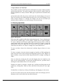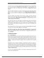
1
P r o C o n f U s e r ’s
G u id e
PMoC
2 2 .3 .2 0 0 3
V e r s i on 1 . 1
Project Plan – Process model configuration using SVG
22.3.2003
ProConf User’s Guide
PMoC
Version
1.1
Date
21.3.2003
Author
Jan Lönnberg
1.0
3.3.2003
Jan Lönnberg
Description
Minor rewrites for clarity. Updated screen shots.
Fixed connection drawing description.
Rewrote from scratch.
Notice: The Guide is definitive. Reality is frequently inaccurate.
Project Plan – Process model configuration using SVG
22.3.2003
Table of Contents
1. Introduction _______________________________________________________4
1.1 Purpose of the ProConf system ______________________________________4
1.2 Concepts in ProConf ______________________________________________4
2. Main parts of the ProConf system _____________________________________5
3. Tasks in ProConf___________________________________________________5
3.1 Importing a component type ________________________________________5
3.2 Defining graphics for a component type _______________________________5
3.3 Creating a new model _____________________________________________6
3.4 Drawing a simple net______________________________________________6
3.5 Setting property values ____________________________________________6
4 Operations in ProConf_______________________________________________7
4.1 Drawing operations _______________________________________________7
4.2 Model operations_________________________________________________8
4.2.1 Creating objects ______________________________________________8
4.2.2 Opening and saving graphics ____________________________________9
4.2.3 Deleting objects ______________________________________________9
4.2.4 Modifying objects ____________________________________________9
4.2.5 Transforming symbols _________________________________________9
4.2.6 Adding terminals to a component type symbol ______________________9
4.2.7 Drawing connections __________________________________________9
4.2.8 Changing attributes ___________________________________________9
Project Plan – Process model configuration using SVG
22.3.2003
1. Introduction
This document describes the purpose of the ProConf system, the most important
concepts used by it and how to use the program. It does not describe installation; this
can be found in a separate installation guide.
1.1 Purpose of the ProConf system
The ProConf system is a software product that can be used for creating process and
automation flow diagrams. The diagrams can be used with simulation software to
examine the behaviour of the modelled processes.
1.2 Concepts in ProConf
The most important concept in ProConf is the component, which is essentially any
object that takes part in the process that is being modelled. A component can include
other components. For example, if you are designing a nuclear power station, your
design would probably consist of a power station component. The power station
component would contain reactor and cooling system components which in turn are
built of other components and so on down to individual pumps and valves. ProConf
does not limit how large or small a component is; you may choose how much detail to
model with yourself to suit your own needs and simulation software.
Every component is an instance of a component type. The component type describes
what the component looks like and which properties it has. In our previous example,
we could have the component type “Acme 123X Multidirectional Air Pump”, with the
ability to both suck and blow at different speeds. When designing the ventilation
system for our power station, we could take two of these, set one of them to blow and
the other to suck (by giving their direction property a value) and set them both to run
at maximum speed (by giving their speed property a value). Properties are defined in a
component type as property types, which describe the type and range of values a
property can have.
The properties of a component include its terminals, which are points on the
component to which connections can be made. For example, a typical pump would
have terminals for water in, water out and electricity in. The electricity in terminal
could e.g. be connected to an electricity output terminal on a generator.
The value of a property is stored in a vector, which is a list of values. The values in
the vector can be of many different types: numbers, textual strings, references to other
properties or even other vectors.
Each component has a net, which is a diagram of the contents of the component. For
example, the net of the cooling system component would show a lot of water pumps,
heat exchangers and suchlike connected to each other.
On a net, components, terminals and connections are represented by symbols, which
are essentially small pictures that can belong to a component type, type of terminal or
type of connection.
Project Plan – Process model configuration using SVG
22.3.2003
Components, component types and symbols are placed in categories to make it easier
to find them. Categories can be nested (placed inside each other).
Every category belongs to a department. Components and component types from
different departments may not be mixed in any way. You may use multiple
departments to separate models designed for different simulators, for example.
2. Main parts of the ProConf system
ProConf is loosely divided into two parts: the tree view and the graphical view. The
tree view shows how different objects contain each other and allows you to edit
aspects of these objects that are not visible in the nets. The graphical view shows
canvases containing the nets and symbols.
Canvas tab
Menus
Drawing
tools
Grid
settings
Tree
Canvas
Figure 1: ProConf GUI
3. Tasks in ProConf
This chapter describes step-by-step the most common tasks in ProConf.
3.1 Importing a component type
Component types are designed by equipment manufacturers or library developers
using an XML editor or a similar tool. These component types (supplied in the GML
format) can be imported into ProConf by selecting a category to place the type in,
right-clicking it and selecting “Import component type”.
3.2 Defining graphics for a component type
If your component type does not have any predefined graphics and you want to use
components of this type in a net, you must define graphics for the component type. To
do this, you must create a symbol for the component type. This is done by creating a
symbol in a suitable category (by right-clicking the category and selecting “New
symbol”) and attaching the symbol to the component type by dragging the symbol’s
tab in the graphics view onto the type.
Project Plan – Process model configuration using SVG
22.3.2003
Once you have created and attached the symbol, you can draw the symbol using the
drawing tools. You can also add terminals to the symbol. To add a terminal to the
component type symbol, you first choose from the terminal toolbar which of the
remaining properties you want to add a terminal for and select the terminal symbol
from the drop-down menu under the property. You must add terminals to the
component symbol to draw connections to or from them.
If you do not have suitable terminal symbols for the terminals, you must create
terminal symbols. To do this, create a symbol as described above. Attach it to a
terminal type by right-clicking the symbol’s tab and choosing “Set to terminal type”.
Enter the name of the terminal type to which you want to connect the terminal. You
can then edit the terminal symbol using the drawing tools.
The drawing operations are described in more detail in section 4.1.
3.3 Creating a new model
In order to create a model, you must have component types defined for every
component you intend to create.
First of all, you will need a category in which to place your model. Create one if
necessary. Drag a component type from the tree into the category to create a
component of this type.
3.4 Drawing a simple net
Once you have a net, you can draw various geometric primitives on it, add
components to it and connect the terminals of the components. The drawing
operations are described in more detail in section 4.1.
To add a new component to a net, drag the component type you wish to instantiate
from the tree onto the net. This will create a new component of the specified type.
To connect terminals in the net, drag a connection symbol from the tree onto the
starting terminal of the connection or select the connection’s appearance using the
connection appearance tool and select the connection tool. You can then specify
points through which the connection passes by clicking them. Right-clicking a
terminal makes it the end terminal of the connection and completes the addition of the
connection.
3.5 Setting property values
To set the value of a property of a component, right-click the component in the tree
and select “Attributes”. This opens a dialogue box with which you can edit the
properties of the component and its values. The properties and their associated values
are displayed as a tree. To change a value, select the property or vector containing it
and modify the displayed value. To add a value to a vector, select the position at
which you want to add a value and click the “Add value” button. To remove a value
from a vector, select the value to remove and click the “Remove value” button. Note
the adding or removing a value may fail or cause many values to be added or deleted
if adding or removing one value would cause the size of the vector to become invalid
(as defined in the property type).
Project Plan – Process model configuration using SVG
22.3.2003
4 Operations in ProConf
The available operations in ProConf can be divided into two groups: model operations
and drawing operations. The model operations affect the process model, while the
drawing operations are merely cosmetic. Both types of operation are described in this
section.
All operations that affect the process model cause the related changes to be saved.
Thus, you need not worry about making sure that you’ve saved your changes. If you
make cosmetic changes to a drawing, the changes will not be saved until you
explicitly tell the computer to save the drawing or close the drawing.
4.1 Drawing operations
select
text
move
arc
line
polyline
freehand
fill colour
ellipse
rectangle
connection
line colour
Figure 2: Drawing tools
Each canvas has a graphics toolbar that contains drawing tools. To use a drawing tool,
select the tool, and then apply it to the graphics. Similar tools are grouped together.
To select a different tool from the group, right-click the group’s icon or click the
small triangle on the icon, and choose the tool you want to use. Figure 1 shows the
drawing tools. From left to right, these are: select, move, line, polyline, freehand, fill
colour (top row) and text, arc, ellipse, rectangle, line colour (bottom row).
To move an object, choose the selection tool, and then drag an object to its new
position.
To draw a rectangle, select the desired rectangle tool (outline or filled) and drag the
mouse from one corner of the rectangle to the diagonally opposite corner. Ellipses are
drawn similarly, except that the mouse drag determines the rectangle enclosing the
ellipse.
Lines are drawn by selecting the line tool and dragging from one endpoint to the
other. Arcs are drawn similarly. To specify the curvature of the arc, you must select it
and drag the centre handle of the arc to a new position.
Polylines are drawn by selecting a polyline type, and then specifying point on the
polyline by clicking them. When you have specified all the point you want, rightclick.
Freehand lines are drawn by selecting a freehand type and dragging over the canvas.
To enter text; choose the text tool, click the position to enter text in and type your text.
Backspace can be used to delete the last entered character.
Project Plan – Process model configuration using SVG
22.3.2003
You can delete objects by selecting them (by choosing the selecting tool and clicking
the object) and choosing “Image/Delete selected objects” or pressing Delete. You
may duplicate objects by selecting them and choosing “Image/Clone selected
objects”.
When you add a new object to an image, it will appear in front of previously drawn
objects. To move it behind everything else, select “Image/Send selected objects to
back”. To move it in front of everything else, select “Image/Send selected objects to
front”.
You may combine several objects into one object; a group. To do this, select the
objects (you can select many objects at once by holding the Shift key while clicking
objects) and choosing “Image/Group selected objects”. To ungroup objects, choose
“Image/Ungroup selected objects”.
The current fill colour, line colour and line width determine which colour and line
width new objects are drawn in. When you select an existing object, the current
colours and line width change to those of the selected object. By changing the current
fill, line colour or line width, you change the fill or line colour or line width of all
selected objects.
By selecting the move tool, you can move the canvas (by holding Shift and dragging)
or zoom it in and out (by holding Shift and right-dragging).
By default, the canvas has a visible grid to aid in positioning objects. To turn the grid
on or off, click “Grid”. If the grid is visible, objects can optionally be “snapped” to it;
locked to the grid whenever they are moved or drawn. To toggle this feature on or off,
click “Gridsnap”.
4.2 Model operations
4.2.1 Creating objects
Most of the stuff in the process models created by ProConf shows up in the tree view.
For this reason, creating new objects is done by right-clicking the object you want to
create a new child object in, and choosing the type of object you wish to create. For
example, to create a category, right-click a department or category and select “New
category”. Departments, categories, symbols, vectors and values can be created in
this way.
Components can be created by dragging a component type into the category or
component you want to create the new component in. Note that this means that the
component does not show up on any net. Properties are created similarly; by dragging
a property type into a component. Component types can only be imported from files;
this is done by right-clicking the category you want to place the type in and selecting
“Import component type”.
To create a new component and add it to a net, drag a component type from the tree
into the canvas showing the net.
Project Plan – Process model configuration using SVG
22.3.2003
4.2.2 Opening and saving graphics
To open a symbol, double-click the symbol or right-click it and select “Open”. To
open a net, right-click the component it belongs to and select “Open net”. Graphics
files can be explicitly saved by right-clicking the canvas’s tab and selecting “Save”.
4.2.3 Deleting objects
You can delete objects in the tree by right-clicking them and selecting “Delete” or
pressing Delete. If the object is also shown in a net, it will be removed from the net.
You can also delete objects that are shown in the tree in the same way as you delete
any other graphical object; by selecting them (by choosing the selecting tool and
clicking the object) and choosing “Image/Delete selected objects” or pressing
Delete.
4.2.4 Modifying objects
All objects in the tree can be renamed by selecting them and then clicking their name
(or pressing F2). You can edit property values this way, too.
4.2.5 Transforming symbols
When a symbol is created, it is merely a piece of graphics; a free symbol. This symbol
can be attached to a terminal type or a component type. To attach a symbol to a
component type, drag its tab (from above the canvases) onto a component type. To
attach a symbol to a terminal type, right-click the symbol’s tab, select “Make
terminal symbol”, and enter the name of the terminal type to attach to. Free symbols
can not be converted to connection symbols; you must create them as connection
symbols.
4.2.6 Adding terminals to a component type symbol
To add a terminal to a component type symbol, choose from the terminal toolbar
which of the remaining properties you want to add a terminal for, select the terminal
symbol from the drop-down menu under the property, and drag the terminal symbol
from the terminal toolbar onto the canvas.
4.2.7 Drawing connections
To draw a connection between two terminals, select the connection type you want,
drag it onto the start terminal, click the intermediate points of the connection, and
finally right-click the end terminal. Alternatively, you can choose a connection
appearance using the connection appearance tools, and then select the connection tool
and click the points on the connection in the order described above.
4.2.8 Changing attributes
Most of the objects in the process model have various attributes that can be changed.
The exact meaning of these is beyond the scope of this documentation; most are
related to simulating the process. For further information, consult the GML
specification. Most of these options can be changed by right-clicking the
corresponding object and selecting the attribute to change.