1
User manual for AC3D v3.4
© Andy Colebourne 2002
AC3D manual version 3.4.1
Contents
INTRODUCTION................................ ................................ ....................................4
Welcome to AC3D.................................................................................................4
AC3D concepts ......................................................................................................4
Windows/Views ................................................................ ................................ .....6
Control Panel ................................ ................................ ................................ .........6
Toolbar ................................ ................................ ................................ .................. 6
Orthographic views ................................ ................................ ................................ 6
The grids ................................................................................................ ............7
Using Background Images................................ ................................ .................. 7
The 3D view................................ ................................ ................................ ...........8
Getting help ................................ ................................ ................................ ...........8
CREATING AC3D OBJECTS ................................ ................................ ................9
AC3D Surfaces ......................................................................................................9
Surface normals ............................................................................................... 10
Creating new objects ................................ ................................ ............................ 10
Polys/polylines/lines................................ ................................ ......................... 11
Sphere’s boxes etc. ................................ ........................................................... 11
Creating other objects................................ ........................................................... 12
Lights................................................................................................ ................... 12
Text...................................................................................................................... 13
Making your own fonts ................................ ................................ ..................... 13
SELECTING, RESIZING AND MOVING .......................................................... 15
Selecting ................................ ................................ ................................ ..............15
Moving ................................ ................................ ................................ ................ 15
Resizing ............................................................................................................... 16
Extending/Negating the selection ................................ ................................ .........16
Selecting in the 3D window................................ .................................................. 16
Hiding objects ......................................................................................................16
Locking objects....................................................................................................17
NAVIGATION AND VIEWING........................................................................... 18
Moving the orthographic views ................................ ................................ ............ 18
Navigation in the 3D window............................................................................... 18
Spin mode................................ ................................ ................................ .........18
Walk mode........................................................................................................18
Resetting views ....................................................................................................19
Viewing the selection ................................ ........................................................... 19
MODEL MANIPULATION ................................ .................................................. 20
Operations on objects ................................ ........................................................... 20
Revolving ................................ ................................ ................................ .........20
Optimize Vertices ............................................................................................. 21
Optimize Surfaces............................................................................................. 21
Re-centre................................................................................................ .......... 21
Minimum-centre ............................................................................................... 21
Fragment................................................................................................ .......... 21
2
Merge............................................................................................................... 22
Explode ................................................................ ................................ ............ 22
Subdivide surfaces................................ ................................ ............................ 22
Operations on surfaces ................................ ................................ ......................... 23
Extruding ................................ ................................ ................................ .........23
Flip normal ......................................................................................................27
Change vertex order................................ ................................ ......................... 28
Divide surfaces.................................................................................................28
Spline surfaces .................................................................................................28
Spike ................................ ................................ ................................ ................ 28
Make hole................................ ................................ ................................ .........28
Bevel ................................ ................................ ................................ ................ 29
Triangulate................................ ................................ ................................ .......29
Cut away object................................ ................................ ................................ 30
Remap texture coors................................ ................................ ......................... 30
Operations on Vertices ................................ ................................ ......................... 30
Snap-together ................................................................ ................................ ...30
Snap-to-grid ................................ ................................ ................................ .....30
Snap-objects-by-vertices................................................................ ................... 30
Snap object vertex pairs ................................................................ ................... 30
Insert Vertex................................ ................................ ................................ .....31
Create surface/object........................................................................................ 31
Create ordered surface ................................ ................................ ..................... 34
Remove surface only................................ ................................ ......................... 34
TEXTURING ................................ ................................ ................................ .........35
Using textures in conjunction with background images ........................................35
MATERIALS AND THE PALETTE....................................................................37
Editing Palette entries................................ ........................................................... 37
LOADING AND SAVING FILES................................ ................................ .........38
Importing other formats................................ ........................................................ 38
Triangle files ....................................................................................................38
Vector files ................................ ................................ ................................ .......38
Exporting files......................................................................................................38
VRML 1................................................................ ................................ ............ 39
VRML 2................................................................ ................................ ............ 39
DIVE ................................ ................................ ................................ ................ 39
MASSIVE ................................ ................................ ................................ .........39
RENDERMAN ................................ ................................ ..................................39
POVRAY ................................................................................................ .......... 39
Triangle files ....................................................................................................40
RENDERING ................................ ................................ ................................ .........41
APPENDIX............................................................................................................. 42
Performance tips ................................ ................................ ..................................42
Keypresses ................................ ........................................................................... 42
Preferences/settings................................ ................................ .............................. 43
3
Introduction
Welcome to AC3D
AC3D is designed to make the designing and building of 3d objects fast and
easy to do. AC3D is used all over the world to create 3D models for games,
rendering images, and for scientific and general data visualisation.
AC3D runs on a wide range of standard hardware. You don’t have to have an
expensive 3D graphics card in your machine (but it certainly helps with more
complicated 3D models).
AC3D is continually being developed. If you think it should be changed in any
way (new features, different methods etc) then please email me. If you think
there's something missing from this manual or if something could be described
better then please let me know.
andy @ ac3d.org
AC3D concepts
This section introduces some of the concepts that AC3D uses to describe 3d
components.
4
Vertex
A vertex is a single point in 3d space. It’s specified by three coordinates x, y
and z. More than one vertex can occupy the same position in 3d space. A
vertex is always owned by a single Object, they cannot be shared between
objects. A vertex is usually part of a Surface, but need not be.
Surface
A surface in AC3D is a list of vertices. Surfaces are one of three types,
polygons, lines or polygon outlines. The type of a surface can be easily
changed. A surface normal specifies the direction a surface is facing. Normals
are used in lighting calculations. Surface normals are automatically calculated
by AC3D. A surface is facing the viewer if the vertices can be seen in an anticlockwise direction. If a surface is set to be single sided, it will only be visible
from the front. Two sided surfaces will be visible from both sides. It is more
efficient to draw single sided surfaces and makes more sense when used as part
of an object such as a sphere (where you can’t see the other side of the
surfaces). Surfaces have a material attribute, which defines the color and
quality (for lighting purposes). Each vertex referenced in a surface has an
associated texture coordinate. Vertices can be shared between surfaces in the
same object.
Object
An AC3D object is a list of vertices, and surfaces that use these vertices. It also
has other attributes such as a name and texture.
Group
A group is a special object which has no surfaces or vertices buy has other
objects as children. Groups are created by selecting two or more objects and
pressing the ‘Group button on the control panel.
Material
A material defines the colour of a surface and also the attributes that define the
way it will react to light e.g. shininess.
Texture
Graphical images can be mapped onto the surfaces of an object. The images are
usually from graphics files such as gif, jpg, bmp etc.
Texture coordinates
When the vertex of a surface is drawn, a texture coordinate specifies the
position of a texture to map to that point. A texture coordinate is a two
dimensional (u,v) value.
Bounding box
When you make a selection of objects or vertices, a green box outlines it. You
can drag, resize or rotate this box to adjust the contents
5
Windows/Views
AC3D has a control panel, on the left, plus 4 other windows - three 2D
orthographic views and a 3D view. Here’s also the menu and toolbar at the top
and an information bar along the bottom.
Control Panel
This is where you control the edit mode and draw modes in
AC3D. It also contains the surface controls, the palette of
materials and the object name field.
The top of the control panel shows information about the
current selection, size and position. When the mouse is being
used to interact with models, this will also display current
positions, distances moved and other information.
Toolbar
This contains buttons for some of the most commonly used functions.
All – select everything.
None – clear the selection.
Del – delete the selected objects/surfaces or vertices.
Dup – duplicate the selection.
Cut, Copy, Paste – uses AC3D’s internal clipboard.
>< - zoom in and out in the orth windows.
Flip XYZ – flip the section about this axis
200%/50%/+10%/-10% - scale the selection.
XY/ZY/XZ/3D/ALL – Maximise a single view or view ALL together
Orthographic views
You primarily interact with models via the orthographic views and view the
model in the 3D window (some selection functions are available in the 3D
window). Each orthographic view shows a two dimensional view of the 3d
world (front, side, plan). Although it’s useful sometimes to work in a single
view, seeing all the windows at once really helps when positioning objects and
laying out scenes.
6
The dividers between the 4 view windows can be dragged to resize the views.
Select individual view by clicking on the view buttons at the top right of the
main window (alternately press F1-F5 for the different views).
The main window size/position and other settings are saved when exit AC3D.
The grids
In the orthographic windows, there are two grids - the draw grid and the snap
grid. Both can be set from 'File->settings' and can be toggled by pressing the
switches at the bottom of the control panel.
The draw grid is purely for visual guides in the orthographic windows.
The snap grid (if on) will snap moving/resizing/creating mouse movements to
an invisible grid.
Both grids don't need to be set the same but they can be.
Using Background Images
Each of the orthographic (2D) windows can display a background image. This
can be very useful for tracing shapes or laying out objects in relation to some
scanned image e.g. a map. Background images are set and unset from the View
menu. All the image formats that are supported by AC3D's texture loaders can
be used.
Load and clear background images from
the view menu.:
Background images will scale and move
with the views. By default, the image will
7
be centred around the origin. You can
move the background image by using
alt and the cursor keys. You can
adjust the scale of the image using
alt+shift then cursor up/down.
Note that the details of background
images are currently not saved when
you exit AC3D.
The 3D view
The 3D view allows you to instantly see changes made to your model and a
preview of the lighting. A fast lighting model is used which will highlight but
not show shadows. The 3D window is primarily for viewing your models but
also allows you to select objects, surfaces and vertices (depending on the Editmode) by holding down the control key and clicking.
Two navigation mode are available in this window – ‘spin’ and ‘walk’.
A 3d grid is available - toggle with 'g'. the grid is always on the XZ plane
(floor).
A single light is provided. It can be switched with 'l' or by using the item in the
3D menu on the control panel.
Getting help
User interface components in
AC3D have ‘balloon help’.
Small ‘tooltip’ widows will
popup when you rest the
mouse pointer over a button or
field label.
When browsing throiught the menu items, the function on each item is
described in the message text at the bottom of the AC3D window.
8
Creating AC3D objects
AC3D Surfaces
Objects in AC3D consist is a list of
vertices and a number of surfaces
that use the vertices. A surface may
be one of three types - Polygon,
Polyline or Line. A polygon is a
filled area, a Polyline is a wire-frame
outline of the polygon (a loop that
joins the start vertex to the end), a line has a specific start and end.
Surface type is changed by selecting some
surfaces and pressing a Surface-type button.
These are near the bottom of the control panel
(Poly, Polyline, Line):
This panel also contains controls to set surfaces to be smooth ‘SM’ or flat ‘FL’.
This determines the way that a polygon is drawn (it has no effect on lines or
polylines):
If a surface is flat-shaded, the colour across
the surface will be constant. If it's shaded then
the colour will be 'graded' depending on
lighting conditions.
Vertices can be shared between surfaces (i.e. one or more surfaces use the same
vertex). If these surfaces are set to smoothed, the effect is of one continuous
'smooth' surface. The vertices MUST be shared for two surfaces to be smoothed
together. This shading is a good way to make smooth looking objects from
relatively simple shapes.
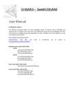
The '1S' and '2S' buttons select how many sides a surface has. (one sided or two
sided). If a surface is single sided then it will only be visible from one side. The
following pictures aims to demonstrate this:
9
In this simple model, there are three objects - a green rectangle, a red rectangle
and a blue ellipse (made by creating an ellipse object and setting it's surface
type to be POLY). The red rectangle has been set to be single-sided '1S'. This
means that it's visible from it's 'front' but not from the back (the second image
shows the whole model rotated). Objects such as spheres and cubes, which don't
have any interior surfaces visible, benefit from a speed optimization when being
drawn with the surfaces single-sided.
Surface normals
The direction a surface is facing is determined by it's 'Normal' (indicated by
arrows in the above diagram). This is a 3D graphics term for a line at right
angles to the surface that indicates a direction. ). Normals are used in the
renderer's lighting calculations. For smooth shading, vertex normals are
calculated by averaging normals of all connected surfaces.
Normals can be visualised in both the orthographic and 3d views (‘Normals’ on
the orth and 3d menus). This preview is useful for solving problems where for
example some surfaces in an object are the wrong way around (this can cause
surfaces to appear missing if they are one-sided, or the smoothing can appear
uneven. Viewing the normals is also with the extrude function.
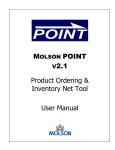
This picture shows two
spheres. The one on the left
show the normals are correct.
The other shows that some
surfaces are facing in the
wrong direction. Notice how
the shading is not consistent.
AC3D automatically
calculates the normals (both surface and vertex).
To flip the direction of a surface, use Surface->Flip normal. (This actually
reverses the order of the vertices in the surface so that the automatically
generated normal faces the opposite way).
Creating new objects
To create an object in AC3D there is palette of
shapes on the control panel:
You create objects by selecting one of these
button and clicking/dragging in one of the orth.
windows.
10
Polys/polylines/lines
To create a poly/polyline/line, click to position each point and either doubleclick or press the middle or right mouse button to end. You can alter the surface
type later from the control panel if you need a different type.
These objects consist of a list of vertices and a single surface. It’s possible to
‘merge’ these surfaces into larger objects. To help with lining up points with
existing points, use the ‘near-snap function (toggle a the bottom of the AC3D
window)-this automatically pulls new points to the nearest.
Polygons should be 3 or more points. Concave polygons are handled by AC3D.
They can be converted to triangles by using the Surface->triangulate function.
It is actually possible to draw a line or poly in different windows - creating a
non planar object. This is fine with lines but is not correct for a polygon which
should have all it's points on the same plane.
Sphere’s boxes etc.
Dragging in a window allows you to specify two of the dimensions for the new
object - the third is specified from the 3D cursor. You can move this by holding
ALT down and dragging the cross around with the mouse. This specifies the
missing position. Most people never use this because it's easy enough to create
an object and position it where you want.
Some objects allow parameters to be set
before creating the object. E.g. spheres and
Meshes can be made from triangles or quads.
Controls for any available parameters will
appear in the control panel underneath the
mode box.
11
You should make objects from triangles if you intend more pull the vertices
about, otherwise you may have non-planar rectangles which can cause problems
with some renderers and raytracers.
Objects can be named - these names are
used when generating output files. The
object name box is at the bottom of the
control panel.:
Object names can only be edited/set in
Group or Object edit mode. Object names can be the same across 2 or more
objects. This can be useful for selecting or finding particular objects with the
Edit->select-by-name function (e.g. you may want to select all objects named
‘chair’).
If you are generating VRML or Dive files, you can associate URLs and other
text with selected objects. This text can be used in a number of the export file
formats that AC3D uses. The names, text and urls are saved in the .ac AC3D
files. Enter text into the field on the Tools->Object Data window. Object
names can also be set in the same dialog.
Creating other objects
At first glance, this set of objects may appear limited, however, it’s very easy to
create other objects from these shapes. E.g. to make a torus shape (‘donut’)
simply create an ellipse and select the Object->revolve menu.
You can easily make a cone in a number of ways. Create a cylinder, select one
end (in vertex mode) and press 'snap together'. A cone made this way will have
the texture coordinates set correctly. For a simpler cone (fewer vertices), no
texture map) you can optimize the vertices. This means that the cone's point will
be one vertex which is shared with all the sides (texture mapping this object will
probably not give satisfactory results). Some other ways of making cones are make a 'disk' and pull the centre point up; revolve a line around an axis. If you
want a base on the cone then - select the bottom vertices and select 'Vertex>Create surface/object'.
Use ‘Extrude’ to add extra parts to objects or give 2d shapes depth. You can
also cut objects into pieces and delete specific surfaces.
Lights
12
Lights are a special kind of object - they have no associated geometry.
At the moment there is only one kind of light - a point light. This is
represented by a point in space marked with this symbol: You will not
see anything displayed in it's position in the 3D window but you should see the
effects of the light on other objects in the scene. Note that there are no shadows
- objects that should obscure the light will not.
Lights are fixed brightness white lights. Select and move lights in Group or
Object select mode.
Lights are generated in POV files and RIB files. You can easily edit their
attributes in the generated files.
This image shows a green sphere with two lights
(indicated by white spheres) - the main headlight
is off. The headlight in the 3D window is toggled
on and off with the 'l' key (or from the 3D menu).
If the headlight is on when POV or RIB files are
generated then a light will be added to the file.
Text
Add-Text is a simple function which
allows a set of objects in an AC3D file
to be treated in a similar way to a text
font. You can view the AC3D font file
by simply loading it in to AC3D.
Essentially, you have a set of objects
which are named to be letters in the alphabet (and other symbols too). Add Text
takes a string (e.g. your name) and duplicates these objects, laying them out
next to each other. The text will be created at the origin and will usually be
facing so that it's viewable in the XY (side) window. This text will be selected
and you can move/resize/rotate it anywhere in the scene. Extrude the text to
make it 3D.
Making your own fonts
A file for use with Add Text is simply an AC3D file with named objects - the
only special thing that you need to do is to ensure that the objects have their
centres minimized (set using the Object->Minimum centre function). To view
object-centres you need to ensure that the '+' button is on (at the bottom of the
control panel). This point is used when lining up text objects. The point is taken
as the start of the 'character' and the width of the object is measured so that the
next character can be placed the correct distance along the line, without
13
overlapping. The font file should be designed to be viewed from the front in the
XY window, since these coordinates are used for positioning the font objects.
You may find the Add text function useful for storing a library of objects e.g.
furniture. Each object can only be indexed by a single character.
To create accurate 3D text objects from TrueType fonts (as used by Windows
etc)- use Font3D to generate DXF files and import them into AC3D. Font 3D is
free to download from http://www-personal.ksu.edu/~squid/font3d.html
Registered users benefit from a special Font3D plugin.
Font3D may no longer still be available from this location. See the AC3D
resources page for more information on how to create text from true type fonts.
14
Selecting, resizing and moving
In AC3D, you select and drag vertices just
like a 2D drawing program. The majority of
selection and manipulation is done through
the orthographic windows although
selection is possible via the 3D view.
Selected components (surface, vertices) are
shown in a different colour and are
surrounded by a ‘bounding box’ (usually green).
Selection is possible in mode/size, rotate
and extrude modes. The default mode is
move/size.
Note that the extrude button is disabled in this picture – it’s enabled only in
surface edit mode.
To select, drag a box over the area you are interested in. The Bounding-Box that
then appears can be dragged or resized directly affecting the
points/surfaces/objects selected
Selecting
The edit-mode defines the granularity of
selection. In Vertex-mode you can drag a box
around or click on a single vertex. In surfacemode you can select one or more surface by either clicking or dragging over an
area. In Object-mode selecting any part of an object causes the whole object to
be selected. In Group-mode you can select a group of objects just by selecting
part of a single object.
Moving
If you drag the green box you can reposition the
selection. Holding the control key down whilst
dragging lets you constrain movement to
up/down or left/right only.
15
Resizing
Drag the handles in the corners of the
bounding box to resize the selection. On the
edge handles, hold the control key down
whilst moving the mouse to resize opposite
edges.
The control key currently has no effect on the
corner handles. Note that it's possible to
resize a selection down to zero width. This is
useful for lining up vertices.
Extending/Negating the selection
Press shift whilst selecting to extend the selection and press shift whilst
selecting with 2nd (or 3rd) mouse button to negate the current selection.
Extended and negate selection work in all select modes e.g. you can
add/subtract whole objects from the selection when in object mode.
This picture shows the top and bottom of a sphere
selected.
To unselect everything, press the ‘None’ button in the
toolbar, menu Edit->select-nothing or click the
mouse outside the bounding box.
Selecting in the 3D window
Hold the control key down and click on a component to select it. This also
works in a similar way to selection from the 2D windows - you can extend or
negate the selection in the same way.
Hiding objects
This allows you to temporarily remove
objects from the views and means that you
can work on much larger models. You can
hide selected objects and hide objects that are not selected. Press 'unhide' to
show all objects. The '3d' toggle determines if the hidden objects are visible in
the 3d window.
16
Locking objects
This is useful for temporarily disabling objects
that are obscuring others. When objects are
locked, it’s not possible to select them.
Locking also helps with the performance when editing large models. It works in
a similar way hiding, only that locked objects are drawn in grey wireframe.
Note that if objects are hidden (or locked) and you save/export the model,
hidden/locked objects will also be saved.
17
Navigation and viewing
Moving the orthographic views
You can shift the views in the orthographic windows with the cursor keys. Press
shift with the cursors keys to move in larger steps. Zoom in and out with control
and the cursor keys or 'z' to zoom-in, 'x' to zoom out.
Dragging the mouse when holding down the middle button ‘pans’ the window.
The right mouse-button zooms. If you don’t have a middle mouse button,
holding down the control key and using the right mouse button will pan the
view.
You can set the window zoom to be the same inside settings dialog (select the
File->edit settings menu), otherwise windows will have independent zoon
settings.
Navigation in the 3D window
There are two viewing modes accessible by pressing '1' and '2' in the 3d window
(or by selecting the menu items in the '3d' menu):
Spin mode
In 'spin' mode - rotate the view by holding down the left mouse button and
dragging. Zoom in and out by holding down the right mouse button and
dragging the mouse vertically. If you have a middle mouse button, holding this
down and dragging will ‘pan’ the view. If you don’t have a middle mouse
button, holding down the control key and using the right mouse button will also
pan the view.
Press 'w' to toggle between wireframe and filled drawing, 't' toggles textures. 'l'
toggles the fixed light. There are switches for the viewing mode in the 3D
menu. The cursor keys can also be used to control the spin (control plus
up/down zoom in/out).
Walk mode
You can navigate using the cursor keys (in a similar way to 'Doom/Quake').
You must be in walk mode. '2' switches into this mode ('1' switches back to spin
mode). Use up/down the cursor keys to move, left/right to turn. Pressing control
with the cursor keys tilts your position and alt moves you left, right, up, down.
You can also control walking with the mouse (this is actually more like ‘flying’)
- the left button turns and moves forward and backward, the right button
controls up/down/left/right movement.
18
Resetting views
Press the 'space' key (when the mouse is over a window) to center that windows
about the origin and reset the zoom levels.
Viewing the selection
Press 'f' to fit the current selection into the current window. 'F' fits the selection
to all windows. Control-F fits the whole model into all views. Use 'g' to 'goto'
the current selection - the window will centre about the centre of the selection.
'G' centres all windows. These options are also in the View menu.
Three functions available from the View menu allow you to centre the 3D view
about the selection, the cursor (that's positioned with ALT-click in the 2D
windows), and reset to view the origin.
19
Model manipulation
Operations on objects
To perform any of the operations on the object menu you must have the selectmode set to group or object.
Revolving
Revolving make copies of the selected objects, rotating each copy, then it
creates surfaces between the copies. This means that it's best to revolve 2d
outlines of shapes rather than filled-polygons. Any revolved line objects are
automatically removed after the revolution. You select the axis to perform the
revolution about.
To create a torus -make a circle in
the Front window:
Select 'Object->Revolve…'
Set the axis to Y and click
Revolve. You should see
something like this:
Select the
'smooth' surface
type (near the
bottom of the
control panel) to
make it appear
rounded
You can also change the degrees of revolution 1-360 degrees.
20
If you have points that you want to be in the centre of the final revolved object (e.g. the start and end points of the cup profile above ) then you should ensure
that these points lie exactly on the axis. You can do this by either drawing the
line with 'gridsnap' on or by snapping those points to the grid or by using Moveto and ensuring that two of the values are zero. If these points are not exactly on
the axis then you'll get a small hole or possibly overlapping surfaces (you can
always use the 'snap together' function and optimize vertices or remove
duplicate points later though).
Optimize Vertices
This function removes duplicate vertices from each selected object. For vertices
to be removed an object must own the vertices and they much match the same
position exactly. The function will share one vertex between each connected
point. This means that vertex normals can be calculated if smooth shading is
needed. It also removes duplicate vertex references from the surface something that might cause a bad polygon.
Optimize Surfaces
Attempts to remove any duplicate surfaces and any polygons that consist of 1 or
2 vertices (you may have these if you have deleted vertices from an object).
Re-centre
If you have object centres visible ('+' at the bottom of the control panel) then
you can re-centre this point about the objects centre of gravity. This can be
useful for specifying where the pivot points or local-origin of an object are.
Minimum-centre
This function sets the object's origin to the minimum xyz of the object. It is used
to create AC3D fonts for the Tools->Add-Text function.
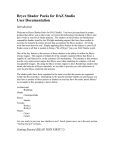
Fragment
Make a selected object into many objects - one object per surface of the original
object. This is useful if you want to break an object into pieces or for texturing
21
each surface with a different picture. This image shows a
sphere that has been fragmented and new objects have
been moved apart. Notice that the surfaces are no longer
'smoothed' together - this is because each surface is now
a separate object and vertices cannot be shared across
objects.
Merge
Places all the surfaces selected objects into one single object. This does NOT
optimise the vertices so that they are shared. (You might want to select 'optimise
vertices after merging if you want a more efficient object and/or smooth shading
across adjacent surfaces)
Explode
This is similar to fragment, you enter a distance and each surface in the select
object is moved by this amount.
Subdivide surfaces
This function can be used to ‘smooth’ the edges of an object. This picture
shows four cubes. The first is a standard box, the others have had surface
subdivision applied one two and three times.
Currently, the surfaces will always be flat after this function. You may want to
select the objects and press ‘SM’ on the control panel to smooth them:
Note that this function always creates triangles. Each subdivision quadruples
the number of triangles in an object.
22
Operations on surfaces
Extruding
Extruding work only in surface mode. Pressing the extrude button on the
control panel when there are one or more surfaces selected enables the function.
The actual extrude is done after you drag the selection.
Extruding is a very powerful function that can be used for a number of tasks. It
works by making new surfaces at the edges of the current selection. The original
selection can be removed and/or copied to the end of the new surfaces.
Selecting one of more surfaces and
selecting the extrude button on the
control panel, brings up the extrude
parameters:
Here you can choose how many new sections to
produce, weather to cap the end with a copy of
the original selection, flip the normals of the new
surfaces and whether to remove the original
surfaces.
After setting these parameters, you drag the
bounding box in the direction you want to
extrude. (You can hold down the control key as you first drag, this will
constrain movements to horizontal or vertical.)
The extrude function is best demonstrated with some examples. This star is
made by creating a 10-sided disk, selecting alternate vertices and shrinking the
selection (using the –10% toolbar button a few times).
23
Note that the magenta lines shown here represent
the normals. This is useful because it can be used
to determine which way to extrude the object to
keep the surfaces facing the correct direction. In
the extrude, if you drag the selection in the same
way as the normals, the resulting shape will hide
the front of the original surfaces. This is good if
you are, for example, extending one side of a box,
but in this case we want the original surfaces to be on the outside of the final
shape. This means that we want to drag the surfaces in the opposite direction
that the normals face. Because we are doing this, we need to ‘flip new surfaces’
so that all the new surfaces face outwards.
This is what happens when we drag the selection up in the plan window.
24
If we ticked ‘remove original’ here then the star that we are dragging will be
deleted:
Here you can see that the original surfaces have been removed to leave a start
shaped box (without a lid). If we’d un-ticked ‘cap end’ then we’d be able to see
right through the star shape.
25
This picture shows what happens when sections is set to 4.
If you need to extend an existing set of surfaces, you may not want to keep the
existing surfaces inside the new object.
Here is a cube that has had ‘Surface->divide’. Two of the surfaces are selected.
We can extend these surfaces without keeping
the original surfaces (since they will not be
visible because they are inside the shape. We
use these settings:
26
To perform the extrusion, we drag the bounding box to the left (in either the
front or plan window), holding down the Control-key as we drag to ensure that
the new surfaces are square to the original. This gives:
When extruding lines, you will probably want to ensure that remove original is
ticked and cap end is un-ticked. This ensures that no lines remain in the new
surfaces.
It’s useful to switch on the display of normals when extruding so check that the
resultant surfaces are facing in the correct direction. If they are not, use surface>flip normals.
Flip normal
27
This effectively changes the direction of the vertices in each selected surface.
This reverses the way that a poly 'faces'. A polygon is defined as 'facing' if the
vertices appear anti-clockwise to the viewer. If a polygon is set to be one-sided
(by pressing the '1S' button on the control panel) then it will only be viewable
from one direction - the direction it is facing. You can switch on the display of
normals I the orth and 3D windows – this can help determine if any surfaces are
facing in undesired directions.
Change vertex order
This changes the order that the surface vertices are drawn by moving the first
vertex to the end of the surfaces vertex list. You can use this to change where
the break in a line is. This can also be used to fix bad polygon, which has the
first three vertices in a non anti-clockwise order - causing the normal (used for
lighting) to be incorrectly calculated. If a polygons shows up as all black, it
may need this function executing on it until it appears correctly.
Divide surfaces
Divide only works on triangles and quads. It makes 1
triangle into 3 surfaces (new vertex at centre). Splits
quad into four smaller quads.
Spline surfaces
Useful for smoothing out a 'line' object and for rounding off polygons. New
points are interpolated between existing points.
Spike
Creates a 'spike' in place of each quad or
triangle selected. The 'spike factor' in the
dialog that pops up - this defines the
distance that the apex of the spike will be
away from the original surface.
Make hole
28
This image shows 4 objects that have had holes made in them - An Ellipse (set
to poly surface-type), a sphere, a cube and a disk. Notice how you can't see the
inside of the sphere or cube through the holes- this is because the default
surfaces for these objects are single-sided and face outwards. To see the insides
though the holes, you'd need to select these objects and press '2S' on the control
panel.
Some concave polygons may have overlapping surfaces after making holes you might need to move some of the vertices.
The size of the hole is specified as a percentage and can be adjusted in File>settings.
Bevel
Creates another surface, which is smaller than the original,
moved away slightly and joined by new surfaces around
the edge. The original surface is discarded. The distance
the new surface is moved and indented is specified in File>settings (Bevel size). Bevelling a concave polygon can
result in new points being positioned incorrectly you may
need to move these
Triangulate
This spits non-triangles (i.e. polygons with more than 3 sides) into more
surfaces, each new surface being a triangle. The operation can fail if it is given a
'bad' polygon - i.e. one that has overlapping edges or duplicate vertices.
29
Some surfaces in file formats generated by AC3D are automatically triangulated
(if they need to be) - some are not though. Renderers that can't cope with
concave polygons may give odd results if they are given them.
Cut away object
Takes all selected surfaces and vertices and puts
them in a new object. This can be useful for
extracting parts of objects. e.g. splitting a sphere
into two.
Remap texture coors
see texturing section.
Operations on Vertices
The Vertex menu is only available when the Vertex edit mode is on and one or
more vertices are selected.
Snap-together
This sets all selected vertices to the same location. The vertices can be in
separate objects or the same object. The point that they are snapped to is the
average of each point.
Snap-to-grid
Moves each selected vertex to the nearest grid position. This may or may not be
the visible grid. The snap grid is defined by 'snap grid' in settings and may be
different to the 'draw grid' (which is the visible grid).
Snap-objects-by-vertices
This is for aligning two objects. You must select one vertex in each of two
separate objects. The objects will be aligned by shifting the objects together so
that the two selected vertices are in the same place.
Snap object vertex pairs
30
This looks at vertices that are selected in two different objects and snaps
adjacent pairs together. This is useful for joining the ends of two objects
together,
Insert Vertex
Inserts a new vertex between each selected pair of
vertices. If you insert a vertex between two vertices of
connected surfaces (i.e. along a shared edge) then two
different vertices will be made. If you want these to
become the same vertex then you should select the
object and choose Object->Optimize vertices. Insertvertex is useful for adding extra points into a line. An example is to create a grid
object (which is made from lines) in a power of 2 dimension e.g. 8. Press 'Insert
vertex' 3 times (2^3=8). You should now have a grid where you can lift each
point and create a 3d graph.
Create surface/object
This function uses a technique called 'convex hull' to create a new object that
surrounds the vertices that are selected. This is very useful for joining complex
objects together or for simplifying the creation of some complex shapes.
31
These two pictures show the function being used to join a cylinder to a cube.
The new object will always be flat shaded but you can set it to smooth by
pressing the "sm" button on the control panel. Note that because this function
makes a new object, the vertices are not shared with the old objects. If you
want to make the whole shape smooth then you need to merge all the objects
together (object->merge) and then optimize the vertices (object->optimizevertices)
A second example uses a number of simple objects, which are 'shrink-wrapped'
by this function. In this case we are creating the fuselage of an aircraft. The
objects are ellipses and a single red box. Any AC3D objects can be used this
way, either lines or polygons. The color of the objects is not important. It’s the
actual vertices that are used in the calculation.
32
To get a more accurate outline, these shapes could have be made by placing
background images of a real aircraft onto the views and building the shapes on
top of those images.
And after the Surface->Create surface-object menu function has been selected:
33
This picture shows the fuselage object created from the simple shapes. It’s been
dragged to the side of the original objects, which still remain in the scene.
It’s important to note that the hull created is ‘convex’. This means that if there
had been an object that was totally ‘inside’ the encompassing hull, the new hull
object would not have any vertices created at the points on that object.
This function will also create 2 dimensional convex hulls, as long as all of the
selected vertices lie on the same plane. If they are not, a 3d object will be
created.
Create ordered surface
Select individual vertices and create a surface between them. You should select
them in order and anticlockwise (to get the normal facing towards you). If you
need to create your own polygons then it's better to draw 'poly' objects. This
function works by creating a new surface and adding vertices in the order they
were selected. If you select many vertices and they are not selected in exactly
the correct order then a bad surface (crossing edges or non-planar) may be
created.
Remove surface only
Remove any whole surfaces selected - vertices will remain.
34
Texturing
Each AC3D object can have one texture. A texture
is set from the object->texture menu. There are
default texture mappings set for the primitive
objects when they are created, but you might need
to remap the texture coordinates. This is done by
axis (Surface->remap texture coors). Currently
you can map by axis and spherically. To map at
an angle, you will need to rotate the object and then select remap-texture-coors>axis.
You can also modify the texture repeat and texture offset in Object->Texture>set texture repeat/offset.
Surface->remap-texture-coors->(front, side, plan) maps the selected surfaces by
axis. It finds the bounding rectangle of the selection and uses this for the edge of
the texture mapping. Spherical mapping ‘wraps’ the image around a ball and
shrinks it onto the selection.
If you need more than one texture on an object (e.g. a different image on each
side of a cube) then you should fragment the object (or use Surface->cut away
object) and map a texture on to each of the sub-objects created.
AC3D loads a number of different
picture file formats for textures. These
include .gif, jpeg etc. More image file
formats are available as plugins. To see
which formats you can load, see the load
texture dialog.
Note that some export formats (or rather the programs that load the files) do not
support all the texture file types that AC3D supports. You should ensure that
you are using the correct format texture for the correct export file type e.g. .jpg
or gif for VRML.
Using textures in conjunction with background images
It can be useful to use the background image as a texture on the final object.
This example shows how the wing of an airplane model is mapped. The picture
of the plane is loaded into the plan view window of AC3D and the wing is built
up over it. If the wing object was selected and texture mapped (to the plan
axis), you'd end up with the whole picture, including the sky, mapped on to the
wing object. The solution is to create a 'dummy' object, in this case a rectangle
over the edge of the picture, which when selected along with the wing, makes
the full extent of the texture mapping go to the rectangle.
35
This picture shows the wing object and the rectangle. The rectangle will be
deleted later.
The same model after the selecting Surface->remap-texture-coors->plan in
vertex mode.
The rectangle can then be deleted and you have a wing which is correctly
texture mapped. Note that the image of the plane's cockpit is in the middle of
the wing. The fuselage will hide this when that's added. Making two separate
wings and using the same technique would have worked fine too.
36
Materials and the palette
The scrolling window of buttons near the
bottom of the control panel represents the
colours/materials available for setting on you
models. The default colour for an object is
palette entry 1 (usually white)
Press a button to select a colour for the selected objects/surfaces. Setting the
material of surfaces works in all selection modes but for a surface to change
color in Vertex mode it must have all it's vertices selected.
You can affect the overall look of a texture you alter the colour of a surface
which is textured (the colour will 'show through' the texture) If you want the
texture to appear as the original coloured image then the surface colour should
be white.
To find the material index of an existing polygon, select that surface and the
message at the bottom of the AC3D window will display the material number.
Editing Palette entries
You can find a menu on each palette
button by pressing the right mouse button.
From here you can edit a colour or add a
new one (a copy of the selected one will
be added to the end of the list).
Note that the colour on the palette button
represents the diffuse RGB values for that
material. It's quite possible to get the
rendered colour looking something totally
different from that by setting other
material parameters.
If you save a model with different
colours/materials then palette buttons will
be appended to the list when it's loaded in the future.
Transparency is supported in the palette but for purposes of speed, the surfaces
are not sorted when they are rendered into the views.
37
Loading and saving files
You can load and save AC3D format files. An AC3D file is a text file
describing the geometry of a model. AC3D files retain all available information
about a model built with AC3D e.g. textures, surface settings, materials, object
data etc. Other file formats exported by AC3D will not retain all of this
information. You should always save your models in AC3D format to ensure
that you do not lose this detail.
Developers can view a description of the file format on the AC3D home page.
Loading a file does not clear the current model - this allows you to have a
'library' of useful objects and load them in when you want.
Importing other formats
See the File->Import menu for a list of file types you can import.
Full registered versions of AC3D come with a number of extra Import/Export
plugins that handle more file formats – they are not documented here.
Here are some formats that may be useful for importing your own model data.
Triangle files
the format of triangle file is: each line contains 9 floating point numbers and one
hex value e.g.: 0.0 0.0 0.0 1.0 0.0 0.0 1.0 1.0 0.0 0xffffff represents 3 vertices of
a triangle. hex value is 0xRRGGBB col - in this case white duplicate vertices
are aggregated when loaded.
The simple format of triangle files might allow you to import models from other
formats more easily than converting them to DXF or something else.
Vector files
This is another simple format for importing 2D vector data. Each line should
consist of a number of vertices followed by that many x/y coordinate pairs e.g.
3 0.5 0.5 2.5 2.5 10 5
This represents a line with 3 vertices (0.5, 0.5)(2.5, 2.5)(10, 5)
Exporting files
AC3D can generate output files for many different formats. Support for extra
file formats can be added by plugins. See File->export for a list of the output
files supported. Not all are mentioned here.
38
VRML 1
URLs (set from the object data dialog) are used so that objects will be selectable
in the appropriate browser. You can switch output of normals and textures in the
File->settings window.
VRML 2
Materials are not present in the file, only colours. This is due to a backwards
step in the design of VRML2 - you can only index colours, not materials. URLs
(entered in Dive object data) are ignored. Output of normals and textures is
switchable via Settings. Note that texture files are supposed to be a different
format in VRML2. They were RGB in VRML1 but this has been changed.
DIVE
Dive files will handle textures. The Dive generation will include the dive data
(if you have input any) this is usually TCL code. If an object has a URL then the
object will be a dive gateway. See www.sics.se/dive for more info about the
Dive VR system.
MASSIVE
Massive is a distributed VR tele-conferencing system written by Chris
Greenhalgh at Nottingham University in the UK. It runs on SGI and Sun
platforms. For more details, see:
http://www.crg.cs.nott.ac.uk/~csm/massive.html
RENDERMAN
These files are used in a raytracer. See http://www.bmrt.org for a good
rendering tool (BMRT) and other pointers to Renderman related stuff. The eye
viewpoint is defined by your view position in the 3D window (approx). Note
that lines don't make sense in a raytracer and will not be output. If you get any
polygons with one or two vertices only, you may get a bad-polygon message. If
you want to clean these away use 'Object->optimize surfaces'. Textures from
picture files are not supported although there may be a way that this can be
accomplished by using a custom shader - see the URL above for more details.
Any polygons that need triangulating (breaking up into triangles) will be
triangulated.
POVRAY
Povray is a very popular raytracer see www.povray.org for more info. The eye
viewpoint is defined by your view position in the 3D window (approx). The
colour palette is output at the top of the file (each entry has the same number as
the AC3D material). The properties can be altered easily to provide different
surface types and textures (you might need to add some #includes to get
39
external definitions). The light is output at the end of the file. The lights position
is the same as the viewers. The POVRay output is based on triangles - lines will
be ignored and polygons with > 3 vertices will be triangulated automatically.
The latest povray exporter supports textured objects. You should ensure that the
format of the texture picture files you use are compatible with POVray. You
may need to Surface->triangulate objects before outputting them to povray file.
Triangle files
see loading triangle files for a description of this format. This format is very
simple and is easy to parse.
40
Rendering
The "Render" button in the tools menu can be configured to automatically
launch your favourite renderer. The command executed when the button is
pressed is entered in the settings.
The command is actually a TCL string. TCL commands are separated by ';'. by
default, AC3D is configured to generate a POV file, then execute povray. An
example command for POV is:
ac3d write_POV ac3dpovfile.pov ; ac3d execute {"C: \Program
Files\POV-Ray for Windows v3.5\bin\pvengine.exe" /RENDER
ac3dpovfile.pov }
you may need to edit this command and set the correct location of the povray
program.
and for BMRT:
ac3d write_rib /tmp/ac3dribfile.rib ; ac3d execute { rendrib -d
/tmp/ac3dribfile.rib &}
The first part sends a message to AC3D to write a POV file. The second part
sends a message to AC3D to execute the povray program. This will only work if
povray is somewhere on the default search path - you might need to specify a
full pathname to the binary program. The execute command must be surrounded
by {} NOT quotes (").
Under WINDOWS it's slightly different:
ac3d write_POV ac3dpovfile.pov ; ac3d execute {"C:\Program Files\POV-Ray
for Windows\bin\pvengine.exe" /RENDER ac3dpovfile.pov }
For other renderers - the other AC3D write_ commands are:
write_dive
write_vrml
write_massive
write_rib
write_POV
41
Appendix
Performance tips
Rendering more polygons takes more time. As you edit and create more
objects, the rendering will take longer. Here are some tips to help you edit larger
models more effectively.
Switch to wireframe viewing. This is much faster to render.
Use object hiding and locking. This reduces the graphics load.
Edit in only one maximised view. This prevents all views from being updated
every time you make a change.
Polygons with more than four points will be triangulated when they are
rendered. Once you have finished creating your objects, triangulate them to
make them slightly faster to draw.
If surfaces can only be viewed from one side, set them to single-sided. This is
slightly faster to draw.
Switch on move-wireframe in both the orth and 3d menus. This temporarily sets
the drawing to wireframe when being panned or zoomed using the mouse –
much faster.
Keypresses
Key shortcuts for menu items are shown on the menus. Other keys can be used:
In orthographic (2D) windows:
Key
Function
Cursor-keys
move view
Shift-Cursor
move view faster
Control-up
zoom in
Control-down
zoom out
Shift-Control-up
zoom in with larger step
Shift-Controldown
zoom out with larger step
Alt-Cursor
move background image
Alt-shift-cursor
up/down
Scale background image
42
Backspace/Delete
delete current selection
Space
home windows to origin and reset zoom
in each window
t
Toggle textures
o
set select mode to OBJECT
v
set select mode to VERTEX
s
Set select mode to SURFACE
m
set drag mode to MOVE
e
set drag mode to EXTRUDE
f
fit selection to window
fit selection to all views (Control f fits
everything to all views)
F/control-f
G
centre window at centre of selection
H
hide selected objects
z
zoom in
x
zoom out
Some of the keys for the 3D window have equiv. menu item in the 3D menu.
In the 3D view:
Key
W
Function
Wireframe/filled toggle
T
toggle textures
L
toggle headlight
G
toggle 3d grid
f
fit to window
Cursor-keys - spin model in 'spin-mode', control viewpoint in a similar way to
'quake' in walk mode e.g. left, right, forward back, alt-up/down move up/down,
control-up/down tilt.
Preferences/settings
The settings in File->settings are saved automatically when you exit AC3D.
This automatic saving can be switched off (you must save the settings with this
off for the change to be remembered). Some settings such as the background
colours of the windows can be adjusted in the settings file but beware –
43
changing values that you don’t know about could cause AC3D to behave
unexpectedly or crash.
Under Unix, the settings are saved to $HOME/.ac3dprefs. Under Windows,
they are saved to the users home directory as ac3dprefs.txt.
44