1
Operating Instructions
MEW00460
Revision 4
TLON Manager V1.2
Author:
Jan Pettersson
Date of issue: 2004-05-24
File name: MEW00460 (Rev 4).doc
Date of rev:
2009-04-14
This page has deliberately been left blank.
Panasonic Electric Works Fire & Security Technology Europe AB
MEW00460 Rev: 4
Operating Instructions TLON Manager V1.2
Table of contents
1
Introduction________________________________ 3
1.1
Definitions ________________________________________ 3
2
3
TLON Manager kit 1595 / 1595SE _____________ 4
Installation of the LonWorks PCC-10 card ______ 5
3.1
3.2
Installation of the PCC-10-drivers _____________________ 5
Installation of the PCC-10 PCMCIA card________________ 8
4
5
Installation of TLON Manager _______________ 10
Project ___________________________________ 14
5.1
Planning a Project _________________________________ 14
5.1.1
Channels / Subnets ____________________________ 14
5.1.2
Routers _____________________________________ 15
5.1.3
EBL512 units (nodes) __________________________ 15
5.2
Planning / Creating a project _________________________ 15
6
Create a New Project _______________________ 16
6.1
Installation of a Project _____________________________ 21
7
8
9
Add a Channel ____________________________ 24
Subnet ___________________________________ 25
Add a Router ______________________________ 26
9.1
Installation of Routers ______________________________ 28
10
11
Add a Unit ________________________________ 30
File menu _________________________________ 31
11.1
11.2
11.3
11.4
11.5
11.6
11.7
11.8
11.9
11.10
11.11
New ____________________________________________ 31
Open ___________________________________________ 31
Close ___________________________________________ 31
Delete __________________________________________ 31
Import __________________________________________ 31
Export __________________________________________ 32
Copy from disk ___________________________________ 33
Copy project _____________________________________ 34
NW Wizard ______________________________________ 35
Print __________________________________________ 36
Print preview ___________________________________ 36
12
13
14
Import xif files _____________________________ 37
Remove xif files ____________________________ 38
Remove___________________________________ 39
14.1
14.2
14.3
Nodes __________________________________________ 39
Channels ________________________________________ 39
Routers _________________________________________ 40
15
Maintenance and troubleshooting _____________ 41
1
Panasonic Electric Works Fire & Security Technology Europe AB
MEW00460 Rev: 4
Operating Instructions TLON Manager V1.2
15.1 Wink ___________________________________________ 41
15.2 Replace _________________________________________ 42
15.3 Install ___________________________________________ 42
15.4 Remove _________________________________________ 42
15.5 Move ___________________________________________ 42
15.6 Control _________________________________________ 42
15.7 Save ____________________________________________ 42
15.8 Auto Bind _______________________________________ 42
15.9 Restart __________________________________________ 42
15.9.1 Restart subnet ________________________________ 43
15.9.2 Restart network _______________________________ 43
15.10
Update ________________________________________ 44
15.10.1
Update all _________________________________ 44
15.11
Detail Info _____________________________________ 44
15.12
Property _______________________________________ 46
16
Flowcharts ________________________________ 48
16.1
16.2
16.3
Create a TLON Network ____________________________ 48
Network troubleshooting ____________________________ 51
Network maintenance ______________________________ 52
17
18
Examples _________________________________ 53
Revision history ____________________________ 55
2
Panasonic Electric Works Fire & Security Technology Europe AB
MEW00460 Rev: 4
Operating Instructions TLON Manager V1.2
1
Introduction
TLON Manager is an installation and maintenance tool for the TLON
Network used for the fire alarm system EBL512.
This Operating Instruction describes the most common tasks used
when installing and maintaining a TLON network. It is not a
complete description of the TLON Manager. Basic knowledge of
windows and windows applications is required.
This document describes how to install the LonWorks drivers, the
PCMCIA card (for a laptop PCMCIA-slot) and the PC program
TLON Manager. An example describes how to create and install a
"Project".
1.1
Definitions
PCC-10 card:
An Echelon card that fits in the PCMCIA slot in the laptop
(PC). (PCMCIA = Type II PC Card.)
Unit:
A physical device connected to the network, e.g. an EBL512
unit.
Node:
A logical part of the network.
Channel:
A physical part of the network, i.e. the wires to which up to six
units (nodes) are connected.1 (Compare with a COM loop and
the connected loop units.)
Subnet:
A logical group of nodes (units) on a subnet.1 (Compare with
loop unit grouping into zones.)
Router / Repeater:
Normally a repeater will forward all valid data and a router will
forward all valid data based on its destination address. It is
normally the same unit, configured as a repeater or a router. In
a TLON Network it doesn't matter because all valid data will be
forwarded.
1
In a TLON Network is grouping not used, i.e. a subnet = a channel (one
group). On each "side" of a Router is a Channel / Subnet.
3
Panasonic Electric Works Fire & Security Technology Europe AB
MEW00460 Rev: 4
Operating Instructions TLON Manager V1.2
2
TLON Manager kit 1595 / 1595SE
The kit contains the following:
PCMCIA card PCC-10 Network interface
(PCMCIA = Type II PC Card).
PCC-10 card cable.
(1595SE only) Patch coupler.
(1595SE only) Cable with flying leads.
USB Memory stick containing TLON drivers, TLON Manager,
documentation, etc.
The PCC-10 card is connected to the modular RJ45 connector in
EBL512 via the PCC-10 card cable .
NOTE!
1595SE only:
When the card cable is to be connected to an EBL512 with old
hardware (i.e. a terminal block instead of a modular RJ45 connector),
the Patch coupler and the Cable with flying leads have to be
used.
4
Panasonic Electric Works Fire & Security Technology Europe AB
MEW00460 Rev: 4
Operating Instructions TLON Manager V1.2
3
Installation of the LonWorks PCC10 card
3.1
Installation of the PCC-10-drivers
Before installation, be sure that no other application is running on
your PC.
The USB Memory stick contains the PCC-10-drivers, the TLON
Manager software and documents according to the following tree
view:
< Removable Disk (X:) >
Installation instructions
LonWorks PCC-10
Win2000_XP
Release 2.01
WinNT
Release 1.06
WinVista
Release 2.03
TLON Manager
User manual.2)
(X: = E: / F: etc. depending on which USB connector you use).
Put the USB Memory stick in one of your PC's free USB connectors.
Select the folder and the *.exe file for your type of Windows (e.g.
F:\LonWoks PCC-10\Win2000_XP\Release 2.01\pcx10_20Win.exe)
or F:\LonWoks PCC-10\WinVista\Release 2.03\153-021201A_OpenLDV340.exe).
Double click the file name (e.g. pcx10_20Win.exe) and the following
dialog box displays (not for Windows Vista):
Click "Setup".
NOTE! The dialog boxes can look a bit different or be omitted
depending on the Windows type, language, version, etc. that you use.
2
1595: Operating Instructions TLON Manager V1.2, MEW00460 (i.e. this
document in PDF format.
1595SE: Swedish document "TLON-handbok" in PDF format.
5
Panasonic Electric Works Fire & Security Technology Europe AB
MEW00460 Rev: 4
Operating Instructions TLON Manager V1.2
The following windows displays (not for Windows Vista):
Click "Next".
Accept the Software License Agreement, i.e. click "Yes".
It is recommended to use the default path for the LonWorks files.
Click "Next >". The installation process starts.
If you do not want to view the README file, un-mark the check box
and then click "Finish" to complete the Setup.
6
Panasonic Electric Works Fire & Security Technology Europe AB
MEW00460 Rev: 4
Operating Instructions TLON Manager V1.2
Select "No, I will restart my computer later." and click "Finish".
Click "OK".
Shut down the PC (power off). See next chapter.
7
Panasonic Electric Works Fire & Security Technology Europe AB
MEW00460 Rev: 4
Operating Instructions TLON Manager V1.2
3.2
Installation of the PCC-10 PCMCIA card
First install the PCC-10-drivers, see chapter "Installation of the PCC10-drivers", page 5.
With the PC turned off, insert the PCMCIA card "PCC-10" into
the PCMCIA slot in the PC. (PCMCIA = Typ II PC Card.)
Turn on the PC. Windows will now find the new hardware
device. (Follow any wizard instructions.)
Check in the Control Panel that the LonWorks® Plug 'n Play icon
is created.
Double click the icon to open the following dialog box.
The "NI Application" shall for a laptop PC with PCMCIA slot be
NSIPCC, else NSIPCLTA. For Windows Vista the "Uplink
Buffering" is "6" and the Version is 3.05.000.
Click "Diagnostics…". The following information box shall be
displayed (or a similar depending on the Windows type, etc.):
For Windows Vista the Version: 2.03 and Loaded Image size: 57344.
If "negative" information is displayed, it might depend on a device
collision, etc. Check IRQ addresses and make changes when required.
8
Panasonic Electric Works Fire & Security Technology Europe AB
MEW00460 Rev: 4
Operating Instructions TLON Manager V1.2
Click "OK".
Click "Transceiver…" in the "Plug ’n Play" dialog box.
Transceiver type shall be FT-10.
Click "OK" in the "Plug 'n Play" dialog box.
If the following displays, click "Yes".
9
Panasonic Electric Works Fire & Security Technology Europe AB
MEW00460 Rev: 4
Operating Instructions TLON Manager V1.2
4
Installation of TLON Manager
Before installation, be sure that no other application is running on
your PC.
Before installation of this version, uninstall any other version of
TLON-Manager.
First install the PCC-10-drivers and the PCC-10 PCMCIA card, see
chapter "Installation of the LonWorks PCC-10 card", page 5.
The USB Memory stick contains the PCC-10-drivers, the TLON
Manager software and documents according to the following tree
view:
< Removable Disk (X:) >
Installation instructions
LonWorks PCC-10
Win2000_XP
Release 2.01
WinNT
Release 1.06
WinVista
Release 2.03
TLON Manager
User manual.3)
(X: = E: / F: etc. depending on which USB connector you use).
Put the USB Memory stick in one of your PC's free USB connectors.
Select the "TLON Manager" folder and the SETUP.EXE file (i.e.
F:\TLON Manager\SETUP.EXE).
Double click the file name (SETUP.EXE):
If the following displays, click "OK".
3
1595: Operating Instructions TLON Manager V1.2, MEW00460, i.e. this
document in PDF format.
1595SE: Swedish document "TLON-handbok" in PDF format.
10
Panasonic Electric Works Fire & Security Technology Europe AB
MEW00460 Rev: 4
Operating Instructions TLON Manager V1.2
NOTE! The dialog boxes can look a bit different or be omitted
depending on the Windows type, language, version, etc. that you use.
Click "Next".
It is recommended to use the default path for the TLON Manager
files.
Click "Next".
It is recommended to use the default path for the LonWorks files.
Click "Next".
11
Panasonic Electric Works Fire & Security Technology Europe AB
MEW00460 Rev: 4
Operating Instructions TLON Manager V1.2
Click "Next".
Click "Next".
Click "Finish" to finish the TLON Manager installation.
In the following folder you will find a Shortcut to TLON Manager 1.2
and TLON Manager 1.2 Help respectively:
C:\Documents and Settings\All Users\Start Menu\Programs\TLON
Manager 1.
It is possible to send the "Shortcuts" to the desktop.
NOTE!
After a program installation it is always recommended to restart the
PC.
12
Panasonic Electric Works Fire & Security Technology Europe AB
MEW00460 Rev: 4
Operating Instructions TLON Manager V1.2
It is also recommended to check that the path is correct, i.e. do as
follows:
In Windows Explorer, use the right mouse button and click "(My)
Computer", in the menu select (System) Properties. Open the
"Advanced" (System Settings) tab and click "Environment Variables".
Check in "User variables" that the Path is: C:\LonWorks\bin
(If not, change it.)
The following message might appear:
If this message appears:
- Open "Control Panel".
- Open "LonWorks Plug 'n Play".
- Change something, click "Apply",
click "OK".
- Open "LonWorks Plug 'n Play"
again and change back to correct
settings, click "Apply", click "OK".
For Windows Vista the following is valid:
Right click the "TLON Manager 1.2" icon
on your Desctop.
Select "Properties" | "Shortcut" | "Advanced".
Put a check mark in the "Run as Administrator" checkbox.
Click "OK" | "OK".
Double click the "TLON Manager 1.2" icon
Manager 1.2".
13
to start "TLON
Panasonic Electric Works Fire & Security Technology Europe AB
MEW00460 Rev: 4
Operating Instructions TLON Manager V1.2
5
Project
Normally (often), the network planning is carried out "in your office"
before the installation "on site" is finished. Afterwards, during the
commissioning, the TLON network "installation" can be performed.
Naturally, the network planning and the "installation" can be carried
out at the same time ("on site").
TLON network "installation" = download of the project / network data
to the network units (EBL512 and Routers).
5.1
Planning a Project
A TLON Network can consist of two EBL512 units or up to thirty
EBL512 units plus a number of Routers connected via a Backbone
net. In rough outline, there are three types of network:
a) Up to six EBL512 units (nodes).4
b) One Router and up to twelve EBL512 units (nodes) or
one Router because the total cable length (for a channel) can then
be two times the normal length.
c) Two or more Routers, connected via a Backbone net, and up to
thirty EBL512 units (nodes).
Make a schematic drawing of the network, i.e. a drawing showing all
the EBL512 units (nodes), cables and required Routers. (The fire
alarm system's installation drawings can be useful as well as the
planning made with Win512, e.g. system name, control unit numbers,
cables, etc.)
For safety reasons, it is recommended to place all the Routers and the
backbone net together, in a locked cabinet / room.
See also chapter "Examples", page 53.
5.1.1
Channels / Subnets
The EBL512 units (nodes)5 are physically connected to each other via
a network cable. In the LonWorks vocabulary this is called a
Channel. (Compare with a COM loop and the connected loop units.)
The nodes, connected to a Channel, can be logically "grouped" into
Subnets. (Compare with loop unit grouping into zones.)
NOTE! In the TLON Network is only one group used, i.e.
a group = a Channel = a Subnet. In the TLON Manager window (the
tree view) is each Channel / Subnet shown as a Subnet only.
In a network type a) there is only one Channel (Subnet), i.e.
Channel_1. No Channel has to be added.
4
For safety reasons, it is recommended not to have more than six nodes in a
channel / subnet.
5
A TLON connection board 1590 is required in each EBL512 unit.
14
Panasonic Electric Works Fire & Security Technology Europe AB
MEW00460 Rev: 4
Operating Instructions TLON Manager V1.2
In a network type b) there is one Channel (Subnet) on each side of the
Router, i.e. Channel_1 and Channel_2. Channel_2 has to be added.
In a network type c) there is one Channel (Subnet) for each Router
and one for the Backbone net between the Routers (normally
Channel_2), i.e. Channel_1, Channel_2, Channel_3 and so on.
Required numbers of Channels have to be added.
How to add Channels to the Project, see chapter "Add a Channel",
page 24.
5.1.2
Routers
After the Channels have been added, the Routers have to be added to
the Project if it is a type b) or c) network. See chapter "Add a
Router", page 26. Use Channel_2 for the Backbone net.
NOTE! In the TLON Manager window (the tree view), the Routers
are not shown (i.e. no icon and no text).
5.1.3
EBL512 units (nodes)
After the Channels and the Routers have been added, the EBL512
units (nodes) have to be added to the Project, see chapter "Add a
Unit", page 30.
5.2
Planning / Creating a project
Here follows a rough overview:
Create a New Project. (File | New)
Add required Channel(s). (Network | Channel) Note, the Subnet(s)
will be automatically added when you add the Channel(s).
Add required Router(s). (Network | Router)
Add the nodes. (Subnet_x_x | New unit) Normally EBL512 units
but a Security Management system can also be added.
Installation. All the data will be downloaded in the units (EBL512,
etc.). Installation order:
1. Routers. (Router | Install)
2. Nodes. (Node | Install)
Update all and Save all. All network data will be updated and saved
in all the units, i.e. all the units will get information about all other
units.
NOTE! In EBL512 some data will be saved in the TLON connection
board 1590 and some data in the Main board 1556.
Wink. This is a way to check if a unit is correctly connected and
installed in the network.
15
Panasonic Electric Works Fire & Security Technology Europe AB
MEW00460 Rev: 4
Operating Instructions TLON Manager V1.2
6
Create a New Project
This example will show how to connect two EBL512 units (CU00 and
CU01) in a TLON network.
Start TLON Manager, i.e. double click the
desktop.
1.
Select "New" in the File menu.
A dialog box displays:
16
icon on your PC's
Panasonic Electric Works Fire & Security Technology Europe AB
MEW00460 Rev: 4
Operating Instructions TLON Manager V1.2
Name
Type a name for the project. Normally, use the same name as
the "System Name" in Win512, e.g. System_xyz. Max. 23
characters.
Path
The path will be automatically created when you type the name,
e.g. C:\LNS\System_xyz.
Network interface
Look in the Control Panel | Lon Works Plug 'n Play dialog box
(Device selected). Select the same here (normally "LON1").
Import xif
In a TLON network where only EBL512 units6 shall be
connected, mark the EBL512/GW512 checkbox (default).
If a Security Management system also shall be used in the
TLON network, mark the check box respectively.
NOTE! Development and improvement may result in new
units / Security Management systems that can be connected in
the TLON network. New .xif files can be imported and .xif
files can be removed via the "Network" menu.
2.
Click "OK" to save the settings and close the dialog box.7
The TLON Manager window displays:
6
EBL512 units only or EBL512 units and Router(s).
7
An information box "Initiating network" will be shown.
17
Panasonic Electric Works Fire & Security Technology Europe AB
MEW00460 Rev: 4
Operating Instructions TLON Manager V1.2
= Channel_1
3.
In this example, no Channels or Routers shall be added. Now
the units (i.e. EBL512) have to be added. Select the
Subnet_1_1 icon and click "New unit".8
4.
The following dialog box displays:
Name
Type a name. Normally can the default name (Node_n) be used.
Max. 14 characters.
Number
The number can be 00-29, i.e. CU00-CU29. Normally use the
same number as the node number.
Type
8
Or click the right mouse button to get a pop-up menu (select "New unit")
or select "Unit" in the "Network" menu.
18
Panasonic Electric Works Fire & Security Technology Europe AB
MEW00460 Rev: 4
Operating Instructions TLON Manager V1.2
Depending on what is selected in the "Create Project" dialog
box (Import xif) and if xif files have been imported, see chapter
"Import xif files", page 37, there might be one or more types
available. Normally only:
EBL512 / GW512
For an EBL512 unit select "EBL512 / GW512"
Subnet
See chapter "Planning a Project" ("Channels"), page 14.
Select a subnet. In this example, select "Subnet_1_1" (default).
Channel
See chapter "Planning a Project" ("Channels"), page 14.
Select a Channel. In this example, select "Channel_1" (default).
Description
A description of the node may be written here.
characters divided on three rows.
Max. 64
5.
Click "OK" to save the settings and close the dialog box.
The following dialog box displays:
6.
a) If you are going to carry out the installation instantly, i.e. if
you are "on site" and your PC is connected to an EBL512 unit
connected (attached) to the TLON Network, jump to chapter
"Installation of a Project", page 21.
b) If you are going to carry out the installation later, i.e. if you
are "in your office", click "No". (This is probably the most
frequently used alternative when creating a new project.)
7.
TLON Manager starts a "binding" process.9 After that, a new
EBL512 unit ("Node_0") is added to the Subnet_1_1 icon
(Channel_1) in the tree view:
9
The binding time is depending on the number of nodes in the network.
19
Panasonic Electric Works Fire & Security Technology Europe AB
MEW00460 Rev: 4
Operating Instructions TLON Manager V1.2
Regarding the red frame around the EBL512 unit (Node_0), see
below.
8.
Add the wanted number of EBL512 units (nodes) the same way.
In this example, add one more unit (Node_1):
The window shows the Project name "System_xyz" and that
you have one Channel (= Subnet_1_1) with two EBL512 units
(Node_0 and Node_1).
20
Panasonic Electric Works Fire & Security Technology Europe AB
MEW00460 Rev: 4
Operating Instructions TLON Manager V1.2
The red frame around each EBL512 unit indicates that the unit
is not installed.
9.
6.1
The "project" is now created and can be closed or installed (see
"Installation of a Project" below).
Installation of a Project
The TLON Network cable installations have to be finished and the
EBL512 units have to be connected to the network.10
NOTE! In a Project with Routers, they have to be installed before the
nodes, see chapter "Installation of Routers", page 28.
Plug the PCC-10 card cable into any of the EBL512 units on
Channel_1.11 The modular connector "J2" (RJ45) is to be used.12
10.
11.
12.
Start TLON Manager and Open the "Project"
(e.g. "System_xyz").
In the dialog box select the Node_0 icon and click the right
mouse button to get a pop-up menu.
Select "Install"
If you have made a jump from "6 a)" at page 19:
Click "Yes".
13. A dialog box displays:
("Activate service pin" is blinking.)
In the EBL512 unit that is intended to be number zero (CU00),
shunt momentarily the "Service" pins (JP 3) on the main board.
An "id-number" will be transmitted and (for a second) be shown
10
A TLON connection board 1590 is required in each EBL512 unit.
11
From now on, use the same EBL512 unit at all times or another EBL512
unit on the same Channel.
12
It is situated close to the connector "J1" (for PC / Win512 connection), i.e.
below and to the right of the keypad on the EBL512 front.
21
Panasonic Electric Works Fire & Security Technology Europe AB
MEW00460 Rev: 4
Operating Instructions TLON Manager V1.2
in the "Neuron id" field and the type of node (EBL512 /
GW512) will be shown in the "Type of node" field.
Since the check box is marked13, TLON Manager will
automatically start binding the node in the database.14
The EBL512 unit "Node_0" is now created and installed in the
network.15 When the binding process is completed, there shall
be an EBL512 unit icon with no red frame around it.
14.
Do the same for the EBL512 unit "Node_1".
15.
In this example are now all nodes installed. Click "Update all".
TLON Manager will now re-connect and update all the nodes
installed in the network. In the "Status line" you will get
information regarding which unit (node) is being updated and
finally "All units updated".
If one or more nodes failed to be updated, the following box
displays:
13
If the check box is un-marked you will have to click "OK" to continue.
14
The time is depending on the number of nodes.
15
To check this you can select the EBL512 unit and click "Wink". The
buzzer in the EBL512 unit shall sound for approx. one second.
22
Panasonic Electric Works Fire & Security Technology Europe AB
MEW00460 Rev: 4
Operating Instructions TLON Manager V1.2
Write down the nodes in the list, so that you can update the
nodes later. In this example is only "Node_0" not updated.
Click "OK".
16.
All the nodes that were not updated (by "Update all") have now
to be manually updated, one by one. Select the Node_x icon
respectively and click the right mouse button to get a pop-up
menu. Click "Update".
17.
When ALL nodes are updated, click "Save all". The Network
information will now be saved in each EBL512 unit, one by
one.16 (Some information will be saved in the "TLON
connection board" memory and some in the "Main board"
memory.)
18.
It is highly recommended to restart each EBL512 unit.
16
In the "Status line" you will get information regarding which unit is being
saved and finally "All units saved".
23
Panasonic Electric Works Fire & Security Technology Europe AB
MEW00460 Rev: 4
Operating Instructions TLON Manager V1.2
7
Add a Channel
Regarding Channels in a TLON Network, see chapter "Planning a
Project" ("Channels"), page 14.
1. Select "Channel" in the Network menu.
Name
A default name for the "next" Channel to be added. Normally
the default name is used but information can be added.17
Type
The type used with EBL512 units is TP/FT-10 (default). If a
fibre optic network is to be used (via Fibre Optic/Twisted Pair
LonWorks Routers), the type is FO-10. Other units may use
other types of communication.
"List field"
A list of the existing Channels in the Project.
New
Adds the "next" Channel in the "Name:" field (e.g. Channel_2).
Remove
Removes a selected Channel.
Save
Adds the Channel in the "Name:" field (e.g. Channel_2) to the
list.
Cancel
Closes the dialog box when the required number of channels is
added.
NOTE! In the TLON Manager window (the tree view) the Channels
are not shown, only the Subnets. (Channel_1 = Subnet_1_1)
17
E.g. Channel_2_Backbone.
24
Panasonic Electric Works Fire & Security Technology Europe AB
MEW00460 Rev: 4
Operating Instructions TLON Manager V1.2
8
Subnet
Regarding Subnets in a TLON Network, see chapter "Planning a
Project" ("Channels"), page 14. Normally you do not add any
Subnets. When you add the required Channels and Routers, the
Subnets will be automatically added and shown in the tree view.
E.g. Subnet_1_1 = Subnet_Subnet 1_Channel 1 (i.e. Channel 1)
Subnet_1_2 = Subnet_Subnet 1_Channel 2 (i.e. Channel 2)
Subnet_1_3 = Subnet_Subnet 1_Channel 3 (i.e. Channel 3)
…and so on.
Use the dialog box "Create subnet", only to view the list of Subnets in
the Project.
1. Select "Subnet" in the Network menu.
Name
A default name for the "next" subnet to be added. Normally the
default name is used but information can be added.18.
Number
A default number for the "next" subnet to be added.
"List field"
A list of the existing Subnets in the Project.
New
Adds the "next" subnet in the "Name:" field (e.g. Subnet_2).
Remove
Removes a selected subnet.
Save
Adds the Subnet in the "Name:" field (e.g. Subnet_2) to the list.
Cancel
Closes the dialog box.
18
E.g. Subnet_1_2_Backbone.
25
Panasonic Electric Works Fire & Security Technology Europe AB
MEW00460 Rev: 4
Operating Instructions TLON Manager V1.2
9
Add a Router
Regarding Routers in a TLON Network, see chapter "Planning a
Project" ("Routers"), page 14.
Two or more Routers have to be connected via a "Backbone net". Use
Channel_2 for the Backbone net.
Select "Router" in the Network menu. A dialog box displays:
Router
Write a name (and/or a number) for the router (e.g. Router 1).
Type
In a TLON Network is normally the type "Learning Router"
used (default) but it is also possible to use the type "Configured
router" or the type "Repeater".19
Near, Far
A router must be installed between two channels. If there is
only one channel in the list field (see below), required new
channels must be created, see "Channel" in the Network menu,
before any router(s) can be added.
A router has connections for one Near channel (e.g. Lon A) and
one Far channel (e.g. Lon B).
Select a channel in the drop-down list respectively.
19
This is the same intelligent hardware, set for one of the types. Do not use
a Repeater, which has no intelligence.
26
Panasonic Electric Works Fire & Security Technology Europe AB
MEW00460 Rev: 4
Operating Instructions TLON Manager V1.2
Near: On the first router, the channel where the TLON
Manager PC is to be connected (Channel_1). On any other
router, the channel nearest the first router.
Far: On the first router, the backbone net channel
(Channel_2). On any other router, the channel on the other
side of the router respectively.
"List field"
A list of the existing Routers in the Project. (The Subnets will
be automatically added for the Channel respectively.)
New
Clears the field / resets it to the default value.
Remove
Removes the selected router (in the "Name" column).
Install
Select a Router (in the "Name" column). Click "Install". A
dialog box "Install" displays. See "Installation of Routers"
below.
Update
Updates the selected router. See "Update" below.
Change
When an existing Router has to be replaced, you do not have to
add a new Router and install it. Yet, follow the same procedure
as for "Install" but click "Change" instead of "Install". See
"Installation of Routers" below.
Reset
Sends a reset message that will clear some statistics and
configuration data.
Status
Select a Router (in the "Name" column). Click "Status" and the
status will be shown in the "Status" column (e.g. "Not
installed").
Save
A dialog box "Install" displays.
a) If you are going to carry out the installation instantly, i.e. if
you are "on site" and your PC is connected to an EBL512 unit
connected (attached) to the TLON Network, jump to chapter
27
Panasonic Electric Works Fire & Security Technology Europe AB
MEW00460 Rev: 4
Operating Instructions TLON Manager V1.2
"Installation of Routers" below.
b) If you are going to carry out the installation later, i.e. if you
are "in your office", click "No". (This is probably the most
frequently used alternative when creating a new project.). The
specified Router will be added to the list.
More Routers can now be added.
For installation of Routers, see the chapter below.
Cancel
Closes the dialog box.
NOTE! In the TLON Manager window (the tree view), the Routers
and Channels are not shown (i.e. no icons and no text). Only the
Subnets are shown.
9.1
Installation of Routers
The TLON Network cable installations have to be finished and the
Routers have to be connected to the network.
NOTE! The Routers have to be installed before the nodes can be
installed otherwise there will be no communication with the nodes
connected on the Channels "on the other side" of the Router(s).
Plug the PCC-10 card cable into any of the EBL512 units.20 The
modular connector "J2" (RJ45) is to be used.21
1. Start TLON Manager and Open the "Project".
2. In the Network menu select "Router".
3. In the dialog box select a Router (in the "Name" column) and
click "Install".
If you have continued from page 27, i.e. chapter "Add a Router"
"Save" alt. a), the following dialog box will be displayed:
Click "Yes".
4. A dialog box displays:
20
From now on, use the same EBL512 unit at all times or an EBL512 unit
on the same Channel (Channel_1).
21
It is situated close to the connector "J1" (for PC / Win512 connection), i.e.
below and to the right of the keypad on the EBL512 front.
28
Panasonic Electric Works Fire & Security Technology Europe AB
MEW00460 Rev: 4
Operating Instructions TLON Manager V1.2
("Activate service pin" is blinking.)
On the specified Router, push the "Service" button. An "idnumber" will be transmitted and (for a second) be shown in
the "Neuron id" field and the type of node will be shown in
the "Type of node" field.
Since the check box is marked22, TLON Manager will
continue, i.e. to start the binding process.23
The router is now created and installed in the network.24
5. When the Router is installed, click "Update".
If a Router fails to be updated, a message will be displayed.
Click "Update" again (until it is correctly updated).
6. When all the Routers are installed, the EBL512 units (nodes)
can be installed, see chapter "Installation of a Project", page
21.
22
If the check box is un-marked you will have to click "OK" to continue.
23
The time is depending on the number of nodes.
24
To check this you can select the EBL512 unit and click "Wink". The
buzzer in the EBL512 unit shall sound for approx. one second.
29
Panasonic Electric Works Fire & Security Technology Europe AB
MEW00460 Rev: 4
Operating Instructions TLON Manager V1.2
10
Add a Unit
Regarding EBL512 units (nodes) in a TLON Network, see chapter
"Planning a Project" ("EBL512 units (nodes)"), page 14.
In the TLON Manager window's tree view, select a subnet icon25 (e.g.
Subnet_1_1) and click "New unit".26
The following dialog box displays:
The dialog box and the following actions are described in the example
in chapter "Create a New Project", page 18 and continues in chapter
"Installation of a Project", page 21.
NOTE! When all the EBL512 units (nodes) have been installed, it is
very important that you click "Update all" and "Save all" as described
in the example. After that it is recommended to restart each EBL512
unit.
25
NOTE! In a network with two or more Routers, Channel_2 is normally
used for the Backbone net and no EBL512 units (nodes) must be connected.
26
Or click the right mouse button to get a pop-up menu (select "New unit")
or select "Unit" in the "Network" menu.
30
Panasonic Electric Works Fire & Security Technology Europe AB
MEW00460 Rev: 4
Operating Instructions TLON Manager V1.2
11
File menu
11.1
New
Creates a new Project. Se chapter "Create a New Project", page 16.
11.2
Open
Opens an existing Project in TLON Manager's common data base.
Select a project in the list and click "OK".
11.3
Close
Closes the project that is open.
11.4
Delete
Deletes an existing Project in TLON Manager's common data base.
Select a project in the list and click "OK".
11.5
Import
To be able to open a Project that for example has been copied from
another PC (see chapter "Copy from disk", page 33) or to be able to
open an "old Project" when a new version of TLON Manager has
been installed, the Project has to be imported to TLON Manager's
common database.
Select "Import" in the File menu. The following dialog box displays:
Find and select the folder (Project) to be imported. As default, TLON
Manager saves all projects in: C:\LNS\
The Project name will be the same as the folder name. You may use
this name or change it.
31
Panasonic Electric Works Fire & Security Technology Europe AB
MEW00460 Rev: 4
Operating Instructions TLON Manager V1.2
11.6
Export
Used when you want to export a Project. You will get a copy of the
Project in another folder. From this folder it is possible to copy the
project to e.g. a floppy disk / CD. Export can be used if you want a
backup of the project27 or want to use the Project in another PC.
Select "Export" in the File menu. The following dialog box displays:
Select the Project to export. Click "OK".
Find and select the folder to which the Project is to be exported. (As
default, TLON Manager suggests: C:\LNS\)
The "File name" (Project name) will be the same as the folder name.
You may use this name or change it.
Click "Save".
The project will now be copied to the selected folder.
27
NOTE! It is not possible to "upload" data from the TLON Network to
TLON Manager.
32
Panasonic Electric Works Fire & Security Technology Europe AB
MEW00460 Rev: 4
Operating Instructions TLON Manager V1.2
11.7
Copy from disk
Used when you want to copy a Project from a disk (e.g. a disk /CD
made in another PC) to the hard disk drive in your PC. To open the
Project, it has to be imported to TLON Manager's common database,
which you will be asked after the copying.
Select "Copy from disk" in the File menu. The following dialog box
displays:
From
Select the drive. (Default is always C:\lns selected.)
To
In the selected drive, select the folder (Project) to be copied.
The program chooses the same folder name as the name of the
Project and suggests a destination folder. You may use the
name or change it but it is not recommended to change the
destination folder.
Click "OK". The selected project will now be copied and after
that, a dialog box displays:
To be able to open the Project, it has to be imported to TLON
Manager's common database. You can do it instantly by clicking
"Yes" or later, see chapter "Import", page 31.
If you click "Yes" the following dialog box displays:
33
Panasonic Electric Works Fire & Security Technology Europe AB
MEW00460 Rev: 4
Operating Instructions TLON Manager V1.2
Write the name (and directory). Click "OK". The project will now be
imported.
11.8
Copy project
Used when you want a copy of an existing Project, but with a new
name. This is useful when a new similar Project is to be created.
Select "Copy project" in the File menu. The following dialog box
displays:
Select the Project to copy. Click "OK". The following dialog box
displays:
Name
Enter the name of the new project (up to 23 characters).
Path
The path will be automatically created when you write the
name.
Click "OK". The project will now be copied.
34
Panasonic Electric Works Fire & Security Technology Europe AB
MEW00460 Rev: 4
Operating Instructions TLON Manager V1.2
11.9
NW Wizard
Creating large projects may be time consuming since the node binding
time increases in relation to the number of nodes and is also
depending on the PC. If a large project shall be created the "NW
Wizard" is a good help. Here you can define all nodes before binding
them. It doesn’t make the process faster, but the bindings for the
whole project are made "all at the same time", which makes the user
free for other activities during the ("long") binding time.
NOTE! The required channels (subnets) and routers have to be
created before NW Wizard can be used.
1. Select "NW Wizard" in the File menu. The following dialog
box displays:
Name
Type a name. Normally the default name (Node_n) can be used.
Max. 14 characters.
No (Number)
The number can be 00-29, i.e. CU00-CU29. Normally use the
same number as the node number.
Type
For an EBL512 unit select "EBL512 / GW512"
Subnet
See chapter "Planning a Project" ("Channels"), page 14.
2. Fill-in / select the data for a node (Name, No, Type and
Subnet).
3. Click "Add" to add the specified node to the list.
NOTE! The Channel will be automatically added in the list.
35
Panasonic Electric Works Fire & Security Technology Europe AB
MEW00460 Rev: 4
Operating Instructions TLON Manager V1.2
(To remove a node, select the node in the list and click
"Remove".)
4. Add all the wanted nodes to the list.
Here is an example with two EBL512 units (Node_0 and
Node_1) and a Security Management system (Node_29) in
two Subnets / Channels (i.e. there is also a Router in the
Project):
5. Click "Create" to start binding all the nodes in the list to the
Project. (Click "Cancel" to close the dialog box without
binding any nodes.). The binding process might take some
time.
After the binding process, in the TLON Manager window's tree view
there will, in this example, be added three nodes (EBL512 units).
11.10
Print
It is possible to print some information about the project, e.g.:
Project Name
Path
Number of nodes
Number of subnets
Number of routers
Individual node information
11.11
Print preview
A preview of the information that will be printed.
36
Panasonic Electric Works Fire & Security Technology Europe AB
MEW00460 Rev: 4
Operating Instructions TLON Manager V1.2
12
Import xif files
Development and improvement may result in new units, Security
Management systems, etc. that can be connected as a node in the
TLON network. New xif files can be imported to each Project.
Select "Import xif" in the Network menu. The following dialog box
displays:
Select the folder and the xif file to import.
The following are available "today":
Tlonmip.xif
for EBL512 / GW512
SecmasAlarm.xif for TLONDDE Server
Interv.xif
for Securimaster Alarm (1.43-connection)
Click "Open" and the selected xif file will be imported.
It will now be possible to select this new type of node in the "Create
unit" dialog box.
37
Panasonic Electric Works Fire & Security Technology Europe AB
MEW00460 Rev: 4
Operating Instructions TLON Manager V1.2
13
Remove xif files
From each Project, xif files can be removed.
Select "Remove xif" in the Network menu. A dialog box with a xif
file list displays.
In the list, select the xif file to be removed. Click "OK"
It will now not be possible to select this type of node in the "Create
unit" dialog box.
38
Panasonic Electric Works Fire & Security Technology Europe AB
MEW00460 Rev: 4
Operating Instructions TLON Manager V1.2
14
Remove
Everything added to the network, i.e. nodes, Channels, Routers, etc.
may also be removed.
NOTE!! After removing a node you have to do "Update all" units. It
is recommended to do so also after removing a Channel or Router.
14.1
Nodes
There are two ways to remove a node:
a) Select the node to be removed and double click the right mouse
button to get a pop-up menu. Select "Remove".
b) Select the node and click "Remove".
You will be asked if the node really shall be removed. Click "Yes" (or
"No").
14.2
Channels
Select "Channel" in the Network menu. The following dialog box
displays:
Select the channel to remove and click "Remove".
39
Panasonic Electric Works Fire & Security Technology Europe AB
MEW00460 Rev: 4
Operating Instructions TLON Manager V1.2
You will be asked if the Channel really shall be removed. Click "Yes"
(or "No").
14.3
Routers
Select "Router" in the Network menu. The following dialog box
displays:
Select the router to remove and click "Remove".
You will be asked if the Router really shall be removed. Click "Yes"
(or "No").
40
Panasonic Electric Works Fire & Security Technology Europe AB
MEW00460 Rev: 4
Operating Instructions TLON Manager V1.2
15
Maintenance and troubleshooting
Some TLON information is saved in the EBL512 TLON connection
board (1590) memory and some in the EBL512 Main board (1556)
memory.
If only the Main board (1556) is replaced: Do Update and Save, for
the node.
If only the TLON connection board (1590) or if both the boards are
replaced: Do Replace, Update and Save, for the node.
There are a number of functions that are useful for network
maintenance and troubleshooting. The most common are described
below. See also chapters "Network troubleshooting", page 51 and
"Network maintenance", page 52.
15.1
Wink
With "Wink" you can check that the node (e.g. EBL512) corresponds
to the selected node in the TLON Manager window's tree view. A not
connected node, not installed, etc. can not receive a wink message.
There are two ways to send a wink message:
a) Select the node and double click the right mouse button to get a
pop-up menu. Select "Wink".
b) Select the node and click "Wink".
The wink message turns on the buzzer (for approx. 1 second) in the
selected EBL512 unit.
If TLON Manager can not communicate with the node (see the status
line), the following message displays:
Click "OK" to close the message box.
41
Panasonic Electric Works Fire & Security Technology Europe AB
MEW00460 Rev: 4
Operating Instructions TLON Manager V1.2
15.2
Replace
When the TLON connection board 1590 is replaced in an EBL512
unit, select the unit and click "Replace". After that you have to
"Update" and "Save", see below.
15.3
Install
The unit will be installed in the network, see chapter "Installation of a
Project", page 21 and chapter "Installation of Routers", page 28.
15.4
Remove
The unit will be removed from the project.
15.5
Move
A node can be moved from a channel / subnet to another. In the
dialog box, specify the "New location" and click "OK".
15.6
Control
Normally not used in TLON Manager.
15.7
Save
After "Update" (see below) you shall click "Save" so that the updated
data is saved in the unit respectively.
15.8
Auto Bind
Normally not used since it is already set as default in "Settings".
15.9
Restart
You can restart a node in the network with the restart command. In
the TLON Network this command works only on EBL512 units.
Select the node and click the right mouse button to get a pop-up menu.
Select "Restart".
The following dialog box displays:
Click "Yes" (or "No"). If TLON Manager can not communicate with /
restart the node, the following message displays:
42
Panasonic Electric Works Fire & Security Technology Europe AB
MEW00460 Rev: 4
Operating Instructions TLON Manager V1.2
Click "OK" to close the message box.
15.9.1
Restart subnet
You can restart (see above) all the nodes on a Subnet (Channel).
Select the Subnet and click the right mouse button to get a pop-up
menu. Select "Restart". The following dialog box displays:
Click "Yes" (or "No"). If TLON Manager can not communicate with /
restart a node (see the status line), the following message displays:
Click "OK" to close the message box.
15.9.2
Restart network
You can restart (see above) all the nodes in a TLON Network.
Select "Restart network" in the Network menu. The following dialog
box displays:
Click "Yes" (or "No"). If TLON Manager can not communicate with /
restart a node (see the status line), the following message displays:
Click "OK" to close the message box.
43
Panasonic Electric Works Fire & Security Technology Europe AB
MEW00460 Rev: 4
Operating Instructions TLON Manager V1.2
15.10
Update
Normally you update a node (i.e. you download the network
configuration data to the physical node) after it has been installed, see
chapter "Installation of a Project", page 21. Update can also be used
when you suspect that the configuration data in a node is incorrect.
When the TLON connection board 1590 (see "Replace" above) and/or
the Main board 1556 is/are replaced in an EBL512 unit, you have to
update the node.
Select the node and click the right mouse button to get a pop-up menu.
Select "Update".
If TLON Manager can not update the node, the following message
displays:
Click "OK" to close the message box.
After "Update" you shall click "Save" or "Save all".
15.10.1
Update all
All the nodes in the network can be updated (see above) with only one
command. Click "Update all". (See also chapter "Installation of a
Project", page 21.)
15.11
Detail Info
This command asks a node in the network a series of questions, which
will be presented in a dialog box.
There are two ways to get the detailed information:
a) Select a node and double click the right mouse button to get a popup menu. Select "Detail Info".
b) Select a node and click "Detail Info".
44
Panasonic Electric Works Fire & Security Technology Europe AB
MEW00460 Rev: 4
Operating Instructions TLON Manager V1.2
The following dialog box displays:
The dialog box contains a lot of information and a deeper knowledge
of the TLON Network is required to be able to understand some of it.
The information of interest for the average user is explained below.
(In case of no contact, the information is: "No contact with node".)
Name
The name given to the node when it was created.
Type
The type given to the node when it was created (see page 18).
Status
Shows the status of the node. The normal status is "ConfigOnline".
45
Panasonic Electric Works Fire & Security Technology Europe AB
MEW00460 Rev: 4
Operating Instructions TLON Manager V1.2
Channel
Shows the Channel the node is installed on.
Unit no.
The number given to the node when it was created.
Description
Starts with a number for the unit, followed by the Description
given in the "Create unit" dialog box (if any).
Last reset cause
Shows the reason for latest restart of the node.
Transaction timeouts
Shows the number of messages sent but not acknowledged by
all other nodes in the network. The number should be 0 after
the node has been installed. The number may increase if new
nodes are installed. Reset the value (and all the others) by
clicking "Reset".
Transmission errors
Must not increase during a 10-minutes interval.
Test
Shall normally be "Good".
15.12
Property
Use the "Edit node" dialog box to edit the name, number and/or
description of the node.
Select a node and double click the right mouse button to get a pop-up
menu. Select "Property". The following dialog box displays:
NOTE! If the number is changed, the program will "ask" if the node
shall be updated. If the node is not updated, the number in the node
and the number in the program will be different. The node may be
updated later, see chapter "Update", page 44.
46
Panasonic Electric Works Fire & Security Technology Europe AB
MEW00460 Rev: 4
Operating Instructions TLON Manager V1.2
Click "Yes" (or "No"). If TLON Manager can not communicate with /
restart a node (see the status line), the following message displays:
Click "OK" to close the message box.
Update", page 43.
Click "OK" to save and close the dialog box.
47
Panasonic Electric Works Fire & Security Technology Europe AB
MEW00460 Rev: 4
Operating Instructions TLON Manager V1.2
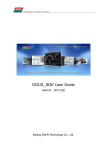
16
Flowcharts
The following flowcharts will help you creating a TLON Network as
well as TLON network troubleshooting and maintenance. The text in
the command blocks refers to the chapters in this document.
16.1
Create a TLON Network
Create a new
project or use an
existing?
Existing
Create
Create a completely
new project or copy an
existing project and
rename it?
Copy
Open a project or
use a copy from a
disk?
Open
Copy from disk
+
Import
Copy
Open
New
New
(Create a project)
Copy project
Continue
48
Panasonic Electric Works Fire & Security Technology Europe AB
MEW00460 Rev: 4
Operating Instructions TLON Manager V1.2
Continued
Unit
What
shall be added?
1. Channel
2. Router
3. Unit
Channel
Router
Yes
Import xif
Need to
import an xiffile?
No
Is there need for
an additional
channel?
Yes
No
Channel
Unit
(New unit)
Router
Yes
Add more?
No
Continue
49
Panasonic Electric Works Fire & Security Technology Europe AB
MEW00460 Rev: 4
Operating Instructions TLON Manager V1.2
Continued
Remove xif
Yes
Is there need to
remove an xiffile?
No
Yes
Should the
project be used in
another PC?
No
Export
Finished!
50
Panasonic Electric Works Fire & Security Technology Europe AB
MEW00460 Rev: 4
Operating Instructions TLON Manager V1.2
16.2
Network troubleshooting
Most of the functions in the flowchart below are described in chapter
"Maintenance and troubleshooting", page 41.
Wink
Yes
What physical
unit (EBL512) is
programmed in
TLON Manager?
No
Detail info
Yes
Detailed
information about
the node and its
status?
No
Update
Yes
Download the
network config.
data to a physical
node?
No
Finished!
51
Panasonic Electric Works Fire & Security Technology Europe AB
MEW00460 Rev: 4
Operating Instructions TLON Manager V1.2
16.3
Network maintenance
Most of the functions in the flowchart below are described in chapter
"Maintenance and troubleshooting", page 41.
Remove
Yes
Remove a Node,
Channel or
Router?
No
Restart
Yes
Restart a physical
node (EBL512)?
No
Property
Yes
Change the name,
number or
description for a
node?
No
Finished!
52
Panasonic Electric Works Fire & Security Technology Europe AB
MEW00460 Rev: 4
Operating Instructions TLON Manager V1.2
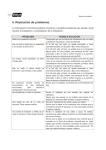
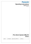
Examples
An example of a network with eight EBL512 units (> six units), i.e. a
Router is required:
Router
C hannel_1
100R
100R
Channel_2
100R
TLO N
Manager
10 0R
up to 270 0 m
17
53
Panasonic Electric Works Fire & Security Technology Europe AB
MEW00460 Rev: 4
Operating Instructions TLON Manager V1.2
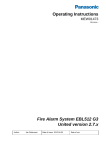
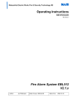
An example of a network with twenty EBL512 units, connected via
four Routers and a Backbone net. (100R in the figure should be
105R, 1%, 1/8W.)
For safety reasons, put all routers together in a locked cabinet/room.
Routers type FT-10<->FT-10
Backbone net, Channel_1
2
The SysMik GmbH Universal Router is recommended
Keep wires shorter than 1 meter
Near
Far
Near
Near
100R
Channel_2
100R
Channel_3
100R
Channel_4
100R
Channel_5
100R
100R
1
Far
Far
Far
up to 270 0 m
(depending of type of cable)
Near
100R
100R
PC
100R
100R
54
Panasonic Electric Works Fire & Security Technology Europe AB
MEW00460 Rev: 4
Operating Instructions TLON Manager V1.2
18
Revision history
Revision 1
- Company name and logotype changed to Panasonic
- Elucidations and small corrections in the document.
- Chapter 4. Information added (red font colour).
Revision 2
- Chapter 3. Drivers for Windows 95/98 have been removed.
- Chapter 4. Installation via Floppy disk has been removed.
Revision 3
- Info revised, added or deleted in the following chapters:
1, 1.1
2
3.1, 3.2
4
6, 6.1
7
8
9
10 (footnote 25)
15.11
17
Revision 4
Some Windows Vista information.
- Info revised, added or deleted in the following chapters:
3.1, 3.2
4
55
This page has deliberately been left blank.
Panasonic Electric Works Fire & Security Technology Europe AB
Jungmansgatan 12, SE-211 19 Malmö, Sweden
Tel.:+46(0)40 697 70 00 Fax: +46(0)40 697 70 99
[email protected] www.panasonic-fire-security.com