1
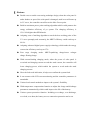
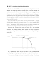
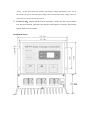
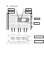
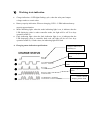
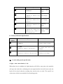
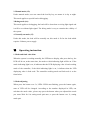
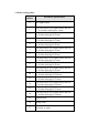
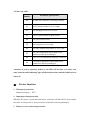
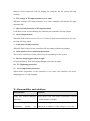
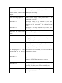
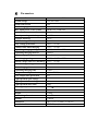
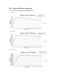
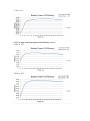
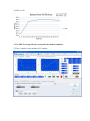
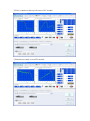
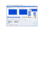
SR-MT Maximum Power Point Tracking Series Solar charge controller User Manual Specification: Model: SR-MT2420 Battery Voltage:12V / 24V Charging Current:20A Discharge Current:20A Max. Power of Solar Panel:260W/12V; 520W/24V Max. Voltage of Solar Panel:150V Dear users: Thank you very much for choosing our products! Please read the manual carefully before using our controllers. Ⅰ. Feature Double crest or multi crest tracing technique design, when the solar panel is under shadow or part of the solar panel is damaged, multi crest will turns up in I-V curve, the controller can still trace the Max. Power point. Built-in maximum power point tracking algorithm which could promote the energy utilization efficiency of pv system. The charging efficiency is 15%~20% higher than PWM mode. Adopting sorts of tracking algorithm to track the best working point of the I-V curve promptly and accurately, the MPPT efficiency could reach up to 99.9%. Adopting advanced digital power supply technology which make the energy conversion efficiency reach up to 97%. Four stage charging mode: MPPT-equalizing charge-boost voltagte charge-floating charge. With current-limiting charging mode, when the power of solar panel is oversized and charging current exceeds the rated current, the controller will lower charging power, which enable the system to work under the rated charging current. Have the fault code indication, it helps user confirm the system fault. It can connect with LCD screen monitoring and the controller parameters is amendable. Various load control methods to improve the system’s flexibility. With temperature compensation function to adjust the charge and discharge parameters automatically, which could improve the life of the battery. Various system protection function. Including over-charge, over-discharge, over-load, over-heat, the battery reverse connection protection and so on. Ⅱ. MPPT charging algorithm Instruction The full name of the MPPT is maximum power point tracking. It is an advanced charging way which could detect the real-time power of the solar panel and the maximum point of the I-V curve that make the highest battery charging efficiency. Contrast with the traditional PWM controller, MPPT controller could play a maximum power of the solar panel so that a larger charging current could be supplied. Generally speaking, the MPPT controller’s energy utilization efficiency is 15%~20% higher than PWM controller. The voltage of the solar panel is about 12V when General controller is charging while the highest voltage of the solar panel is about 17V, so it doesn’t play the largest power of the solar panel. MPPT controller overcome this problem by adjusting the input current and voltage constantly to realize the largest input power. Meanwhile, the maximum power point will change due to the surrounding temperature and sunshine condition. MPPT controller will adjust the parameter constantly according to different conditions to make the system working in the largest power point. Working point of the general controller Current Maximum power point 12.0V 17.5V 22.0V Voltage As a charging stage, MPPT can’t be used alone. It must be combined with ascending charge, floating charge, equalizing charge to complete the battery charge The controller will judge the battery’s voltage before working. If the battery voltage is higher than 13.2V(*2/24V), the controller will judge the battery working as full charge state then the controller will enter into floating charge stage but not equalizing charge or charge hint. When the battery’s initial charging voltage below 13.2V (*2/24V), the charging process is: MPPT-equalizing charge-boost voltage charge-floating charge. The course of equalizing charge is 1 hour, ascending charge is 2 hour, and equalizing charge interval is 30 days. Charging curve as below: Ⅲ. Usage suggestion 1. The controller will identify the battery voltage automatically. Please connect the battery first and ensure the connection is reliable. 2. MPPT controller is designed according to solar panel’s I-V curve, so when the controller connect the general constant voltage DC source, the controller may not work. 3. Advice is installed in the ventilated and heat dissipated environment due to the controller will fever during operation. 4. The controller will detect the surrounding temperature to compensate the battery charging voltage so ensure the controller and battery is in the same environment. 5. Choosing the proper cable with enough capacity to avoid redundant power loss in the circuit. Too much circuit loss may lead to wrong judgment. 6. Full charge is very important for the battery. The battery should be full charged at least once a month or the battery will suffer permanent damage. The battery can be full charged only when the input power of the battery is more than power consumption of the load. 7. Please do not dip the controller into the corrosive liquid or the controller will be damaged and release harmful gas. 8. The solar panel’s terminal voltage may exceed human safety voltage when connect 24V system, when manipulation is needed, please use insulating tools and ensure the hands dry. 9. Because the battery store lots of energy, do not allow the battery short circuit in any case. We suggest tandem connect a fuse on the battery 10. The battery may release combustible gas, please far away from the spark. 11. Ensure the children are far away from battery and controller 12. Please abide by the battery manufacturer’s safety suggestion. Ⅳ. Installation and use instruction 1. Fix the controller: Fix the controller onto the surface of the specific place. Keep a certain distance between the controller and fitting surface to assure heat dissipation 2. Wire preparation: Adopt the wire matching the current,plan the length of wire, strip 5mm insulation of one side of the controller terminal and try to decrease the length of the connected wire so that a reduction in electrical loss. 3. Connect to the battery: connect the battery wire to the controller firstly,Pay attention to the “+” and “–”, in case of reverse connection. If connected well, the indicator light will be on. Otherwise, please check the connection. If reverse connection, controller will not working but not damage the controller. 4. Connect to the solar panel: Pay attention to the “+” and “–”,not reverse connect. If ample sunshine, controller will show charging mode. Or should check the connection is right or wrong. If solar panel under the sunshine will produce voltage immediately. If use 24V or more than 24V system, the solar panel voltage will exceed to body safety voltage, when use please prevent you self from electric shock. 5. Connect Load:Connected the load to controller,make sure the current cannot over the rated current, and notice the positive and negative electrode. Prevent the system from reverse connect. Installation image: Ⅴ. Controller image Charge lamp Mode lamp Battery lamp Fault lamp Setup Button LED display + - Solar panel +-+ Battery - Load External LCD connector Outer temperature probe Ⅵ. 1. Working state indication Charge indication: 4 LED light flashing cycle, when the solar panel output voltage reaches a certain value. 2. Battery capacity indication: When no charging, LED1 ~ LED4 indicates battery capacity approximation. 3. 4. Mode indicating light: when the mode indicating light is on, it indicates that the LED displaying value is under controller mode, the light will be off if no keys operation within 5s. Fault indicating light: when the fault indication light is on, it indicates that the LED displaying value is controller fault code; the light will be off if no keys operation within 5s, if fault exists, the indicating light will flash. A. Charging status indication specification: Charge at Max. Power, Normally on. Boost charging, slowly flash. ① ② ③ Float charging, single flash. Equalizing charge, fast flash. ④ ⑤ Current limited charging, double flash. Serial Number ① Indicating Status State of charge charge at Max. Normally on. Power. Slow flash. ② (light for 1s,off for 1s,the Boost charging. cycle is 2s) Single flash. ③ (light for 0.1s,off for 1.9s,the Float charging. cycle is 2s) Fast flash. ④ (light for 0.1s,off for 0.1s,the cycle is 0.2s) Equalizing charge. Double flash. ⑤ (light for 0.1s,off for 0.1s, Current reopen for 0.1s , reclose for charging. limited 1.7s,the cycle is 2s) B. Battery Indication Specification. Serial Indicating Status Battery Status Number ① ② ③ Normally on. Slow flash. (light for 1s,off for 1s,the cycle is 2s) The battery voltage is normal. The battery has been over discharged. Fast flash. (light for 0.1s,off for 0.1s,the cycle is 0.2s) The battery is over voltage. Ⅶ. Load working mode specification: 1.Light + time control mode (1-14): When there has no sunlight, the light intensity will fall to start point, the controller will open the load after confirming the start signal and the load will start work, the load will be closed when the working time reach at the set value. The specific set value meets with the set method of load working mode. 2. Manual mode (15): Under manual mode, user can control the load by key; no matter it is day or night. This mode applies to special load or debugging. 3.Debug mode (16): This mode applies to debugging; the load will be shut when receiving light signal and it will be on without light signal. The debug mode is easy to examine the validity of the system. 4. Normally on mode (17): Under this mode, the load will be normally on; this mode is fit for the load which requires 24 hours power supply. Ⅷ. Operating instruction 1. Mode and fault code skim: When the system is working normally, the LED has no display, after press the key, the LED will be on, at the same time, the mode or fault indicating light will be on. If the mode indicating light is on, it indicates that the LED displaying value is load working mode of the controller; if the fault indicating light is on, it indicates that the LED displaying value is fault code. The controller working mode and fault code is as the form below. 2. Mode adjusting When press the button over 3s, LED1~LED4 start flashing, press the button again, state of LED will be changed. According to the number displayed in LED, can calculate the mode value, please stop press the button when you adjusted the mode you want. Wait for 10s setting mode quit auto, or press the button over 3s, setting mode quit. 3. Mode working table: Serial number Parameter Specification 0 Pure light control 1 The load will be on by light control and will be off after delaying for 1 hour 2 3 4 5 6 7 8 9 10 11 12 13 14 The load will be on by light control and will be off after delaying for 2 hour The load will be on by light control and will be off after delaying for 3 hour The load will be on by light control and will be off after delaying for 4 hour The load will be on by light control and will be off after delaying for 5 hour The load will be on by light control and will be off after delaying for 6 hour The load will be on by light control and will be off after delaying for 7 hour The load will be on by light control and will be off after delaying for 8 hour The load will be on by light control and will be off after delaying for 9 hour The load will be on by light control and will be off after delaying for 10 hours The load will be on by light control and will be off after delaying for 11 hour The load will be on by light control and will be off after delaying for 12 hour The load will be on by light control and will be off after delaying for 13 hour The load will be on by light control and will be off after delaying for 14 hour 15 Manual mode 16 Debug mode 17 Normally on mode 4. Fault code table: Serial Number Parameter Specification E0 No fault, the controller is working normally. E1 The PV input terminal is over voltage. E2 The charging current is over value. E3 The PV input terminal is short circuit. E4 The load is short circuit. E5 The load power is over value. E6 The outer ambient temperature is over value. E7 The outer temperature sensor hasn’t been connected or has been damaged. E8 There is over temperature inside the controller. E9 The inside temperature sensor hasn’t been connected or has been damaged. Attention: if no key operation within 5s, the LED will be shut; or if there exist some fault, the fault indicating light will flash all the time until the fault has been removed. Ⅸ. Protect function. 1. Waterproof protection Waterproof degree::IP32 2. Input power limit protection When the PV power exceeds the rated power, controller will limit the PV power under the value of rated power so as to prevent the controller from being damaged. 3. Battery reverse connection protection Battery reverse connection will not damage the controller but the system will stop working. 4. The voltage of PV input terminal is over value. When the voltage of PV input terminal is over value, controller will shut the PV input automatically. 5. Short circuit protection of PV input terminal. Load short circuit will not damage the controller but controller will stop output. 6. Over load protection. When the load current exceed 1.25 (or 1.5) time of rated current and last for 10s (5s), the load will stop output. 7. Load short circuit protection. When the load is short circuit, controller will stop output without any damage. 8. Solar panel reverses connection protection. The reverse connection of solar panel won’t do any damage to the system. 9. Reverse charging protection at night. Prevent the battery from discharging through solar panel at night. 10. TVS lightning protection. 11. Over temperature protection. When inside temperature of the controller is over value, the controller will lower charging power or stop charging. X: Abnormalities and solutions. Abnormalities Solutions Sunny day, without charging Please check if the solar panel connection is correct indication. The battery lightflashes or the contact is reliable. indicating The battery voltage is over value, please check if the quickly, no connection is reliable or if the voltage is over value. output. The battery indicating light The battery is over discharge, it will recover if flashes slowly, without load charging to full voltage. output. All the indicating light is off. Battery power supply fault, please check if the connection is correct. The input voltage of PV terminal is over value, please check if the PV parameter is matched, charging will be recovered if the voltage become lower. The power of PV input terminal is over value, check Fault code E2 if the PV power parameter is matched. Fault code E3, there is no The PV input terminal maybe has been short circuit; check out if it is right. charge. Fault code E1 Fault code E4. The load is short circuit, after the fault been debugged; it will recover the next day or after pressing the key for a long time. Fault code E5 The load power exceeds rated power, please reduce the electric equipment, it will recover the next day or after pressing the key for a lone time. The charging loop of fault The controller is overheated; it will recover when the code E6 and E8 are normal, temperature is lower. but there is no charge. Fault code E7. The outer temperature sensor is unconnected or damaged, check if the connection is correct. Fault code E9. The inside temperature sensor is unconnected or damaged; the inside over temperature protection will not work, if it does some effect to normally use, please find after-sale service. Other abnormalities Please check if the wiring is reliable or the auto identify of 12V/24V is correct. Ⅺ. Parameters Parameter Value System voltage 12V/24V Auto Rated load current 20A Rated charging current 20A Max. input power of PV system 260W/12V; 520W/24V No-load loss <15mA Max. input voltage of solar panel <150V Transfer efficiency ≤97% MPPT tracing efficiency >99 % Over voltage protection 16.5V;×2/24V Limited value when charging 15.5V;×2/24V Equalizing charging voltage 15.2V;×2/24V(25℃) Equalizing charging interval 30 days Boost charging voltage 14.4V;×2/24V(25℃) Float charging voltage 13.8V;×2/24V(25℃) Return voltage when over discharge 12.5V;×2/24V Over discharge voltage 11.0V;×2/24V Boost charging time 2 hours Equalizing charging time 1 hour Temperature compensation -4.0mv/℃/2V; Over temperature protection Yes Light operated open voltage 5V Light operated close voltage 6V Light operated delay time 5min Working temperature -35℃~+65℃; IP level IP32 Weight 1.18kg Max. wiring dimension 12mm2 Altitude ≤3000m Dimension 180.7×115× 72 (mm)(L×W×H) Installation dimension 175.7×70(mm) XII: Typical Efficiency Diagram. 1. 12V system: solar panel power and efficiency curve. ①17V to 12V ②34V to 12V ③68V to 12V ④100V to 12V 2. 24V system: solar panel power and efficiency curve. ①34V to 24V ②68V to 24V ③100V to 24V 3. The MPPT tracing efficiency test(under the shaded condition). ①There’s shadow in the middle of PV module ②There’s shadow at the top left corner of PV module ③Simulate tree shade covered PV module ④There’s wide-range shadow at PV module