1
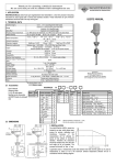
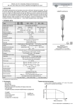
The recommended mounting position of the fork for light, free flowing solids, is
vertical (top) mounting. Side mounting is recommended only in cases when the
fork-tines are easily freed from the process medium. In case of side mounting,
NIVOSWITCH must be mounted with the fork-tines standing vertically.
When determining mounting location, take into account the possible caving or
arching of the material in the tank.
The fork should be protected against falling materials. This is to be done so that
material could not clog between the fork and the protection plate.
R–3–3
R–3–4
4.2. THREE-WIRE DC VERSION
In case of overload caused by short circuit, the transistor will switch on and off,
and the LED will start to blink.
4.2.1. Connector version R – 3 – 3
(LED)
indication
3
"M" - Operation switch
H =High level safe
2
M
H = High density
1
H
L = Low level safe
L
4.2.1.1.
"D" - Density switch
D
L
H
Wiring diagram of the three-wire DC connector version with relay
PNP wiring
4. WIRING
NPN wiring
Terminal block cover can be rotated in 90° steps to ensure appropriate cable
positioning.
R – 3 – 1 with connector
R – 3 – 2 with cable
4.1. TWO-WIRE AC
L = Low density
4.2.1.2.
Wiring diagram of the three-wire DC connector version with PLC
THE UNIT SHOULD NOT BE POWERED UP WITHOUT
GROUNDING AND EXTERNAL LOAD!
+
24V DC
IN
PLC
COM
4.1.1. Model with connector R – 3 – 1
PNP wiring
L1
3
R
2
N
3
R–3–4
4.2.2. Integral cable version
R
2
1
4.2.2.1. Wiring with relay
N
PNP wiring high (H) density (ρ ≥ 0.5 kg/dm3),
1
L1
+
brown
Wiring of Low fail safe mode (L)
brown
Wiring of High fail safe mode (H)
R
black
black
-
blue
Terminal block cover can be rotated in 90° steps to ensure appropriate cable
positioning.
-
white
white
R
blue
grey
grey
Junction
box
+
Junction
box
4.1.2. Integral cable version R – 3 – 2
Two of the signal wires (black and brown) are insulated. Only one of these two
wires is used, depending on the operating mode (High or Low). Remove the
insulation only from the wire corresponding to the desired operating mode.
brown
brown
R
blue
black
N
L1
green/yellow
Junction
box
Wiring of Low fail safe mode (L)
R
blue
black
L1
N
Wiring for L (Low fail safe
operation)
PNP output low (L) density, (ρ < 0.5 kg/dm3)
+
brown
white
R
black
grey
Junction
box
Wiring of High fail safe mode (H)
brown
-
white
black
-
blue
green/yellow
Wiring for H (High fail safe op.)
Junction
box
Wiring of Low fail safe mode (L)
R
blue
+
grey
Junction
box
Wiring of High fail safe mode (H)