1
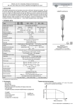
2.6 DERATING DIAGRAMS
Pipe coupling DIN11581
~117
~108
Triclamp (ISO 2852)
Ø 40
Ø 40
Tank pressure (pT) versus the ambient temperature (TM)
Ø 28
~130
~125
1½", 2" Triclamp
(ISO 2852)
A
Temperature limits for DC devices [IL] Current load
[TA] ambient temperature
TYPE
Conn.
A
RCD
DN 40
RD 65x1/6
RCE
DN 50
RD 78x1/6
2.8 MATERIALS
Tank pressure (pT) versus ambient temperature (TM)
for PP flange
With integral cable
With connector
PVC
EPDM
KO35 (1.4571)
Polyamid,
glassfibre reinforced
KO35 (1.4571)
Temperature limits AC [TA] ambient temperature [TM] medium temperature
Klingerit
(1.4571)
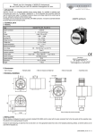
2.7 DIMENSIONS
KO35 (1.4571)
Klingerit
(1.4571)
RLH–301–, RLH–302–
113
RLH–303..30–
Polyamid,
glassfibre reinforced
40
3. MOUNTING
113
BSP1 1/2"
or
NPT 1 1/2"
Prevent device from being damaged during delivery, storage, mounting and test.
40
300-3000
S=55
BSP1 1/2"
or
NPT1 1/2"
137/175
S=55
Adjustable with
sliding sleeve
Flange
s = 41
Ø40
15
~110
Ø 40
~113
~110
RC–3–
13
Ø 40
s = 55
RPH - 112
s = 41
Before installation it is advised to try the operation of the level switch in a small
sample of material in order to set the proper density. Tightening of the model with
thread process connection should only be done with open end SW = 41
Marking
0,2 ... 3 m
0,2 ... 3 m
125 ... 3000
18
1" BSP
For positioning of the fork tine use the marking on the hexagonal neck.