1
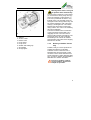
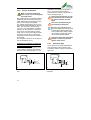
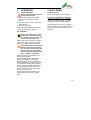
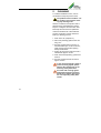
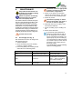
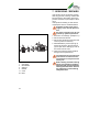
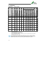
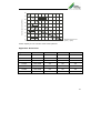
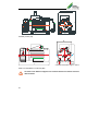
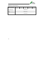
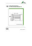
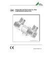
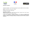
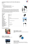
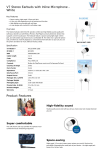
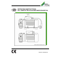
OPERATING INSTRUCTIONS
OIL LUBRICATED VACUUM PUMPS RANGE GA
9000-607-18GB/06.09
The information in this document can be
altered without prior announcement. No
part of these pages may be duplicated or
used, for any purpose, without prior written permission of the company, Dürr
Technik; either electronically or mechanically.
© 2007 by Dürr Technik
All rights reserved.
The use of brand name, trade name, trademark etc. in this manual is covered by
trademark protection legislation and must
not be assumed to be free use.
These operating instructions correspond
with the technical standard of our appliances, subject to alteration and errors
accepted.
2
The present operating instructions give you all the necessary advice for
the proper and safe handling of the oil
lubricated vacuum pumps range GA.
Please read and carefully observe the
operating instructions to avoid mistakes and dangerous situations.
The operating instructions are arranged as follows:
Chapter
Planned purpose
Target group
Chapter 1
Gives you safety advice and important
general information for the appliance.
Installer, operator, qualified
personnel, user
Chapter 2
Contains detailed instructions and advice for the transport, storage, installation and the initial operation of the appliance.
Operator, installer and qualified personnel
Chapter 3
Contains instruction and advice for safe
technical handling of the appliance.
User
Chapter 4-5
Gives detailed instruction for cleaning,
maintenance and servicing the appliance.
Operator, qualified personnel
Appendix
In the appendix you will find important
technical information.
Qualified personnel
3
PREFACE
These operating instructions are valid for
oil lubricated vacuum pumps range GA
hereinafter called product.
The operating manual is only valid so
long as your product complies with the
status described within.
These instructions contain all details required for the transport, installation, operation, shut-down and maintenance of
these products.
Therefore please read the operating instructions carefully prior to the first operation, thus ensuring the safe and economic application of the products.
When a fault occurs or maintenance is
required which is not dealt with in the operating manual, you should contact our
qualified personnel.
All service and maintenance work must
be carried out by qualified personnel.
If service and maintenance work is neglected or carried out improperly, our
warranty will be invalidated.
Should you have any problems understanding the operating instructions our
qualified personnel will be pleased to
help you.
Dürr Group
Dürr Technik GmbH + Co. KG
Pleidelsheimer Straße 30
74321 Bietigheim-Bissingen
Telefon 0 71 42 / 90 22 0
Telefax 0 71 42 / 90 22 99
4
CONTENTS
1.
Introduction and general advice ..6
1.1
Symbol explanation and definition..6
1.1.1 Symbol explanation..........................6
1.1.2 Definitions..........................................6
1.2
General safety advice......................6
1.3
Equipment description.....................8
1.3.1 Agreed application ...........................8
1.3.2 Function description of the
products.............................................8
1.3.3 Delivery schedule / Accessory........9
2.
Transport, Storage.........................10
2.1
Transport and Storage.................. 10
2.3
Assembly notices and initial
operation ........................................ 11
2.3.2 Vibration damping ......................... 12
2.3.3 Assembly position ......................... 12
2.3.4 Noise damping .............................. 12
2.3.5 Hose connections.......................... 13
2.3.6 Electro installation.......................... 14
2.3.7 Protection type............................... 14
3.
Operation .....................................15
3.1
Initial Operation.............................. 15
3.2. Operation ....................................... 15
4.
Operation ....................................15
5.
Cleaning ......................................16
6.
Maintenance.................................17
7.
Servicing / Repairs ......................18
8.
Appendix ......................................20
Appendix 1:Technical Data....................... 20
Appendix 2: Dimensions........................... 21
Appendix 3: Manufacturer Declaration.... 23
Appendix 4: Trouble Shooting.................. 24
Appendix 5: Exploded diagramme .......... 26
Appendix 6: Spare parts list...................... 26
Appendix 7: Accessories list..................... 28
Appendix 8: Addresses............................. 29
Appendix 9: Index...................................... 30
5
1. INTRODUCTION AND
GENERAL ADVICE
1.1
Symbol explanation and
definition
1.1.1 Symbol explanation
In the manual and on the product hand
symbols and pictograms are used whose
meaning you should memorise. These
symbols help you to understand the information in this manual quicker and
make you aware of potential danger or
important advice.
Attention! Danger sign. It points out
danger as well as rules and bans to
prevent personal and /or danger to
property.
Advice! Attention is brought to advise on the handling and economic
use of product.
Warning against electric energy!
Your life could be in danger. Make
sure that all electrical work is carried
out by a qualified electrician.
Warning advice. The product can
start without warning!
Warning of hot surfaces! There is a
danger of burns! Observe especially
that these surfaces may still be hot
after the product has been switched
off. Work near these surfaces only
after they have cooled off.
CE Conformity symbol. It can be recognised by this conformity symbol
that the appliance corresponds to
the safety guidelines of the European Union.
1.1.2 Definitions
User, Operator: The responsible Person
who has the authorisation to use the
product. The user must have been given
6
instructions on the safe handling of the
unit from the appropriate authority.
Operator Authority: Responsible for the
safe installation, regular servicing and
cleaning of the product.
Qualified personnel: Trained by the operating authority or by authorised Dürr
Technik personnel who are aware of the
dangers of the product and familiar with
the technical aspects of the product.
Qualified personnel are trained to carry
out service and repair on the product.
Product: General term used for the oillubricated vacuump pump, range GA.
This can be both an product for installation in machines as well as a ready-touse product.
Product for installation in machines: In
these sections of the texts, particular
points of products for installation in machines are described.
1.2 General safety advice
During use, care and maintenance of the
product, the following fundamental safety
measures must be observed for the protection of the operator, maintenance and service engineers as well as the product:
During the development and
manufacture of the product, the
recognised regulations of the
technical aspects, as well as the
recognised valid standards and guide-lines
were taken into account and used. In addition the product has been de-signed and
constructed in such a way that endangerment through the agreed use are minimized.
Nonetheless we feel obliged to describe the
following safety measures so the remaining
dangers can also be minimized.
Warning! When electrical equipment is being used, the basic safety
precautions must be followed, to
prevent risk of fire, electric shock
and personal injury.
Therefore please read the manual to
hand, prior to starting work. Keep this
manual within reach for the engineer
and the operator. The information
should be passed on to any successor.
During operation of the products the relevant laws and regulations for the place of
deployment must be observed! In the interest of safe operation the authorised
operator and the supervisory personnel
are responsible for keeping within the regulations.
Check during all work on the product for
possible dangers. All parts must be correctly fitted and all requirements fulfilled
to ensure safe operation. Should the
product be damaged in any way, the product should no longer be used. The product should only be repaired by experts.
Mark the defect clearly and pull out the
mains plug, so that until the repair is effected, no accidents or damage can develop through the defective product.
damaged. If there is damage, do not operate the product.
If there is damage, do not operate
the product. Pull out mains plug!
For all maintenance and repair work the
mains plug must be pulled out of the
socket.
Attention! Work on electrical equipment must only be carried out by a
qualified electrician.
Only original spare parts must be used.
Otherwise there may be injury to the
user.
Warning! The use of other spare
parts and other accessories, as stated in this manual, can cause personal injury. Only use spare parts
permitted by the manufacture!
Take account of environmental
influences! Do not operate the
product in a wet or damp environment.
Do not use the power connection line for
purposes it was not meant for. Do not pull
the plug out of the socket by the cable.
Only pull the plug from the socket by pulling the plug casing. Protect the cable against heat, oil and sharp edges.
In dangerous situations or during
technical problems, separate the
product at once from the power
supply (pull the plug).
Check regularly the power supply cable
and the casings of electrical components
and if they are damaged, have them repaired by a qualified electrician.
Check the electrical equipment for external damage before work starts. Check
thoroughly whether lines or cables are
7
1.3 Equipment description
1.3.1 Agreed application
The product is intended for aspiration of
air and non-aggressive gases.
The aspiration of fluids, aggressive or explosive gases is forbidden! It will cause danger to health
and the possible danger of explosion or fire!
The products are supplied as portable,
ready-to-connect products or as products
for installation in machines.
It should only be used if the manufacturer
of the equipment or unit, in which the
product is to be incorporated, has ensured that all requirements for safe operation has been met.
The product is designed for operation in a
dry, well ventilated room.
The product should not be operated in a
damp or wet environment. In addition,
operating near gases or flammable fluids
is forbidden.
1.3.2 Function description of the
products
The product belongs to the group of rotary vane vacuum pumps.
The products are provided with a electricmotor as standard.
With the electric-motor an additional temperature switch is integrated. When the
temperature switch is activated, the
product switches off automatically.
Advice! At unduly high temperatures the product will switch itself off.
8
Warning advice. After cooling off
the product starts automatically.
1
1
2
3
4
5
6
7
8
Silencer
Suction nozzle
Electric motor
Pump casing
Pump cover
Oil filter with sealing cap
Oil chamber
Oil sight glass
The pump part consists of a pump casing
(4), a rotor with 2 vanes, pump cover (5),
and an oil chamber (7) with silencer (1).
The rotor is positioned off centre in a cylindrical casing. The movable vanes are
arranged in lines. During rotation they will
be pressed against the wall of the pump
casing by centrifugal force. The volume
between the vanes alters continuously
during rotation. The vacuum is created by
this volume alteration.
The well conceived interior construction
of the oil chamber ensures that only a
negligibly amount of oil mist in the exhaust air will reach the surroundings. The
greater part of the oil mist is retained
successfully in the volume oil chamber
equipped with cooling ribs and is dripping
back into the oil bath.
1.3.3
Delivery schedule / Accessory
Portable, ready-to-connect products are
supplied as follows as a standard:
The basic version is mounted onto a
baseplate with carrying handle. In addition there is in the motor terminal box an
On/Off switch and a mains lead with fitted
plug. To reduce vibration the baseplate is
fitted with four vibration absorbers.
Even for a portable, ready-toconnect product, please read
Chapter 3, Operation.
9
2. TRANSPORT, STORAGE
2.1 Transport and Storage
The products are sent from the factory in
a specially padded transport carton. With
this the product is safe against transit
damage. Always use the original packaging of the product if necessary.
Transport the product in an upright position.
Protect the product during transport
and storage against dampness and
extreme temperatures. Take special
care that the electrical equipment
does not get damp or wet.
Products must only be transported pressureless. Remove air
from any fitted pressure containers
and lines.
The connections to the oilchamber
have to be sealed with stoppers!
After long periods of storage,
please read Chapter 7, Servicing /
Repairs.
Keep packaging if at all possible.
Environmental rules regarding the disposal of the packaging must be observed
and to assist this please note the labels
on the packaging.
2.2 Storage and transport requirements
Temperature: -25 °C to + 55 °C
The oil must be drained off at
temperatures under 0 °C
Relative humidity: 10% to 90%
(without condensation)
10
Products for installation in machines are
designed for immediate installation.
The portable, ready-to-connect products
are designed for immediate operation.
Products in their original packaging can
be stored till 3 months in a warm, dry,
dust free room. If the products should be
stored long term, e.g. as a replacement
product then they must be protected with
a drying agent. This will prevent corrosion
of the inner parts of the product. When
the product has been stored for a long
time the motor ventilator must be rotated
by hand and then started a number of
times.
2
The mains supply must be disconnected before rotating the
product by hand.
In the event of corrosion or gumming,
clean the product according to Chapter 5.
2.3 Assembly notices and initial
operation
Products for installation in machines may
only be installed by qualified personnel
who are acquainted with the risks of the
product.
2.3.1 Environment conditions
The product must only be installed
and operated in dry, well ventilated
and dust free rooms.
3
Take care when choosing the site for installation that the product is easily accessible for operating, cleaning and maintenance. Especially the connection piece
and the operational parts must be easily
accessible.
The product should be installed on a level
and sufficiently solid surface. To reduce
vibration the supplied vibration dampers
should be mounted. If the vacuum is built
into a machine or housing, it must be
noted that the identification plate is visible
11
and readable, without having to dismantle
the product. If necessary, an additional
nameplate is to be attached. Also ensure
that the connection clamps are easily accessible when taking off or opening the
housing.
Please make sure that the exhaust airway is clear.
When fitting into a housing it should be
observed that the minimum distance is
kept (see fig. 2 and 3). It must also be
noted that there is sufficient ventilation. In
certain cases an independent ventilation
system may be required.
Please make sure that the power line
connection and air hoses are not kinked.
The room temperature must not fall below 12 °C otherwise problem free operation cannot be guaranteed. If the temperatures are too low, difficulties in starting the product result due to the increasing viscosity of the oil.
The ambient operating temperature must
not exceed 40 °C. Operating ambient
temperatures above 40 °C will require
additional ventilation. The product
switches itself off due to overheating
when working in too high temperatures.
Approx. 70% of the product induced
electrical energy is converted into
heat and is given off to the surrounding area.
The motor ventilator normally ensures an
effective pressurised cooling of the product. To do this the air must be able to
flow to and for unhindered. Ventilation
openings must be large enough to allow
this to happen. In unsuitable cases, e.g.
when the product is built-in an independent air cooling system might be required.
2.3.2
Vibration damping
The securing of the product takes place
via the vibration absorbers at the base of
the motor.
12
The product produces vibrations. To
dampen this vibration suitable vibration
absorbers must be used.
Vibration absorbers specially made for
these products can be found in the accessory list. Do not use rigid connections
between the product and the pipeline
system.
The wrong kind of vibration absorbers or the use of rigid connections can damage the product
or the equipment into which the
unit has been installed.
2.3.3
Assembly position
Products should be installed in the horizontal plane (see fig. 2 and 3).
2.3.4
Noise damping
The sound level of the product (without
sound absorber) is 53 dB(A). The sound
level will be reduced with our sound absorber to 43 dB(A) or 51 dB(A).
2.3.5
Hose connections
Connections for the product:
A non-return valve is necessary,
if before switching off the product the evacuated space cannot
be ventilated. The negative pressure will aspirate oil from the
product into the line system.
A suction filter must be built-in
otherwise dust particles can be
aspirated.
When fitting the suction filter
please note the through flow direction (arrow).
4
1
2
3
Oil filling socket
Sound absorber
Suction nozzle
Suction filter with non-return valve
hose connection:
Pull off the protective cap from suction
nozzle and push a vacuum hose (NW8)
onto. Push the suction filter into the hose
(NW8). Note the direction of flow. It is
marked with an arrow pointed on the filter case.
Assembly of non-return valve is recommended over the pump so that oil mist is
returning into the pump.
A suction filter with a non-return
valve is available as an optional
extra. It is easy to change as it is
only pushed into the suction
hose.
5
Suction filter with non-return valve
Connection of sound absorber:
Unscrew plug and fit in attached sound
absorber (2). The evacuated air will be
sucked through the sound absorber (2)
into the surrounding. If the product is built
into a housing and the exhaust air shall
be led out from there a nozzle have to be
mounted instead of a sound absorber.
13
2.3.6
Electro installation
Work on electrical equipment
must only be carried out by qualified electricians!
fluctuation. The capacitor is allowed to
vary ± 10% from the rated capacity.
The electrical connection can be seen on
the circuit diagram (fig. 7).
Please note the direction of rotation (Clockwise when looking at
the motor ventilator from the
back).
The portable product is supplied ready for
installation with on/off switch and power
cable. Please observe implicitly the regulations of the local power supplier.
The voltage and frequency has to correspond to the details indicated on the type
plate. The motors are constructed for
10% over- and undervoltage. Permitted
tolerance for the capacitor: ±10% deviation from the nominal capacity. Please
make sure no connection cable is placed
across the product. The hot surface of
the product could damage the insulation
of the cable.
The electrical connection can be seen on
the circuit diagram (fig. 6).
Products for installation in machines
must be connected according to the
following instructions:
The mains voltage and frequency must
comply with the details on the model label. The motors are designed for ± 10%
The motor can additionally be
protected by a safety fuse.
Because of the small difference between the starting and nominal current
of small motors and the greater tolerance of safety fuses, surges of power
are not easy to control. Only a short
circuit can be protected against.
During the motor has to be fitted
with an overcurrent protection
against short circuit.
2.3.7
Protection type
The machine must only be assembled or
used according to their protection type.
The electric motors conform to protection
type IP 54.
Hi
Ha
S1
U2
Z1
CB
X1
CB
N
L
PE
U1Z2
U1Z2
Ha
U2
Z1
Hi
X1
N
L
PE
6
7
Circuit diagram portable, ready to connect product
Circuit diagram product for installation in
machines
14
3.
OPERATION
3.1
Initial Operation
Before initial operation check the
oil level at the window.
If required, top up with oil as follows:
1. Unscrew cap at oil filling socket
(fig. 4)
2. Fill in pump oil up to mark “max” (see
optional extra).
3. Screw-on cap again
Make sure that installation/mounting is
carried out according to chapter 2.
4. SHUT DOWN
Portable product
Switch off the product at on/off switch.
Product for installation in machines
Switch off the product at the separate
switch (customer specification) or else
through overriding automatic system.
If the product is not used over a lenghty
period of time, disconnect all power to the
product and note the instructions under
chapter 2.
3.2. Operation
Please note whether the oil-free
product has a hot surface. There
is a danger of burns, if these surfaces are touched when hot.
Before daily start of operation, check the
oil level and make a visual check of the
product (e.g. state of the suction filter).
The product must not be working
without vacuum longer than 20
min. In order to ensure safe lubrication of all parts of the pump, a
minimum operational pressure of
pabs ≤ 50mbar is necessary.
Start the product for installation in machines via the apparat.
For the portable product insert mains
plug and activable the on/off switch.
Using the product for short periods the
product will remain cold. There is the risk
of condensation forming in the product.
In order to ensure reliable operation the
product should have continues run for
about 15 minutes or once a week let it
run hot (at least 1 hour).
If these actions aren't possible the oil
change interval have to be in shorter
times.
15
5.
CLEANING
To maintain faultless function, it is recommended to keep the product clean.
The product has hot surfaces. Let
the product cool off before starting any cleaning work.
Clean the surfaces of the product with a
fluff free cloth, special attention particularly the cooling fins and the motor ventilator kept free from dust and pollutants.
If there is hardened oil or dirt inside the
product, the product can be cleaned inside by a cleaning process.
1. Drain of the oil. (Chapter 6.1)
2. Fill in test-(cleaning-)petrol to the marking „min“.
3. Run the product without vacuum, i.e.
with the intake open, for about 30 sec.,
while closing off the intake opening
briefly several times.
4. Switch off the product and leave it at a
standstill for approx. 30 min.
5. Drain off the test-(cleaning-) petrol and
fill in oil.
6. Run the product with full vacuum for
approx. 30 min.
In use of test-(cleaning-) petrol or
similar cleaning agents, please
observe the instructions on the
matching safety data sheet.
For work with cleaning agents
appropriate protective clothing
has be worn. Please observe to
the corresponding safety data
sheets.
16
6.
Collect the used oil in appropriate
container and dispose off under
observation of regulations.
MAINTENANCE
The product has hot surfaces. Let
the product cool off before starting
any maintenance work.
Switch the product off and plug
out mains before any maintenance and upkeep work.
The stated maintenance intervals are guidelines for normal operational conditions. With
extreme operational conditions (e.g. long
working times under full load, high ambient
temperatures, very dusty ambient air, high
humidity) the maintenance intervals must be
shortened. When carrying out maintenance
work the mains plug must be pulled out. Alternatively the product must be voltage free.
4. Switch-on the product; if necessary
close an air exit opening (2). The used
oil is forced out of the oil filling nozzle.
5. Switch-off product.
Refill with oil quantity as stated
(see technical data). Too much or
too little oil leads to damage.
6. Refill with new oil up to marking “max”
at the oil level indicator.
7. Screw on sealing cap on oil filling nozzle.
8. Renew sound absorber.
Vent the suction lines.
6.1
Oil Change (see fig. 4)
We recommend to do the oil change with
Dürr-Special pump oil.
1. Switch-off product.
2. Screw-off sealing cap from oil filling
nozzle (1). Remove gasket.
3. Push hose (NW9) onto oil filling nozzle
and hold over oil collecting basin.
A quick clean and troublefree oil
change is possible with the help of
our oil changing kit. The oil changing kit 1100-002-00 comprises: 1/4 l
special pump oil (for two oil fillings),
1/4 l empty bottle to collect the used
oil, 2 hoses to pump out the used oil
(the hose in use is simply put into
the empty bottle),
2 sound absorbers, 2 screw-off sealing
caps and 2 sealing gaskets.
Operating time
Activity
Measures to be taken
daily
Sight check suction filter
Change dirty filter
daily
Check oil
Oil level has to be between
„min“ – „max“ in case fill up
oil or make oil change
6 months
Oil change
Execution of oil change
Maintenance plan
17
7. SERVICING / REPAIRS
If the product is not functioning properly
after long periods of storing or stand still
because there is dirt inside, remove the
product and clean it (see chapter 5 Cleaning).
If the product is leaking or there are damaged parts remove and disassemble.
Separate product from power
supply. Lines must be pressure
free.
All repair work must only be carried out by qualified personnel.
23
3
5
2
1
18
11
The pump housing and the rotor
must not be loosened from the
electricmotor as they have been
factory set.
8
1
2
3
5
11
23
6
1. Execution of oil change. (Chapter 6.1)
2. Disconnect all hose lines
3. Disconnect electrical connections and
remove product if necessary.
4. Disassemble the product (see fig. 8)
loosen the screws in the pumpcover
(2) and pull off the sealing (5). Pull off
the vanes from the rotor.
5. Clean all component parts and blow
through with compressed air.
sight glass
Oil chamber
Silencer
Gasket
Vane
Filter
Before starting work with cleaning
agents, eye protection, breathing
protection and relevant protective
clothing should be worn. Observe
the instructions on the matching
safety data sheet.
Note fitting position
No liquid and humidity must get
into the product!
All component parts should be given a visual inspection. Change any damaged
parts.
Any parts which have to be returned to
the manufacture for repair should be carefully packaged and noted. Reassembling of the product is made in the opposite order.
Assemble vane (see fig. 8a).
Direction
8a
19
8. APPENDIX
Appendix 1:
Technical Data
max. suction capacity Seff
max. suction capacity
Endpressure P
Noise pressure
level
Motor output
Current1)
r.p.m.
Voltage
Frequenzy
Wweight
Protection type
Art.-No.
Type
Nominal data of the motor
m³/h
l/min
mbar
dB(A)
P1(W)
A
min
V
Hz
kg
IP
-1
GA-401
1188-11EB
2,4
40
5
43
148
170
0,76
0,74
1430
1700
230
50
60
9,6
54
GA-401T
1188-11TB
2,4
40
5
43
148
170
0,76
0,74
1430
1700
230
50
60
10,7
54
GA-401
1188-12EB
2,8
48
5
43
175
190
2
1,7
1430
1700
230
50
60
10
54
GA-501
1245-04EB
3
50
3
51
295
320
1,6
1,4
2820
3330
230
50
60
9,6
54
GA-501T 1245-04TB
3
50
3
51
295
320
1,6
1,4
2820
3330
230
50
60
10,7
54
1225-04EB
4,8
80
3
51
295
320
1,6
1,4
2820
3330
230
50
60
9,6
54
GA-801T 1225-04TB
4,8
80
3
51
295
320
1,6
1,4
2820
3330
230
50
60
10,7
54
GA-801
1)
•
•
•
current at nominal voltage
All models duty rated S1 = 100% duty rated.
The max. allowable ambient temperature is 40°C.
The model designation for products for installation in machines is completed with EB, and the portable,
ready-to-connect appliance with TB.
for example: GA-251 / 1207 – 11 TB
As our products are constantly being updated, they can be at variance with the
listed technical data. Should you use this Operating Manual for outline planning,
please clarify with us the current technical data of the product required.
20
80
Suction capacity Seff(N/min )
70
GA - 801
60
50
GA - 501
40
30
GA - 401
20
10
0
1000 900
GA - 2 51
800
700
600
500
400
300
200
100
0
Absolute pressure Pabs
(mbar) = (hPa)
Suction capacity Seff as a function of the suction pressure
Appendix 2: Dimensions
Type
Article-No.
l
b
h
GA-401
1188-11EB
272
135
185
GA-401T
1188-11EB
272
170
230
GA-401
1188-12EB
270
135
145
GA-501
1245-04EB
272
135
185
GA-501T
1245-04TB
272
170
230
GA-801
1225-04EB
272
135
185
GA-801T
1225-04TB
272
170
230
21
H
L
B
Portable product (TB)
H
B
max
*
min
L
* Vibration absorber height= 20mm
Product for installation in machines (EB)
As motors from different suppliers are used the dimensions and the technical
data can differ.
22
Appendix 3: Manufacturer Declaration
MANUFACTURER’S CERTIFICATE FOR MACHINES
98 / 37 EEC annex II, B
Manufacturer:
Dürr Technik GmbH & Co. KG
Adresse:
Pleidelsheimer Str.30
D-74321 Bietigheim- Bissingen
Reference number:
GA
Product name:
vacuum pump
starting with serial number:
N 000001
Herewith we declare that prior to initial operation, it must be determined that the machine in
which this machine is to be installed, conforms to the stipulations of the applicable machine
directive, 98/37/EEC.
Directive for low voltage 73/23/EEC.
Directive electromagnetic compatibility EMC, 89/336/EEC.
Following harmonized standards are applied:
EN 1012-1:1996-07
EN 1012-2:1996-07
EN 60335-1:2007-02
EN 50106:2001-08
EN 60034-1:2005-04
EN 60034-5:2001-12
EN 55014-1,2:2002-08
Bietigheim- Bissingen, date 24.04.07
ppa. A.Ripsam
vice president Dürr Technik
Signatures registered with original document
Dürr Technik archive
23
Appendix 4: Trouble Shooting
The following description for trouble shooting is only meant for qualified
personnel. Repairs must only be carried out by qualified personnel!
Failure
Cause
• No voltage
•
•
Appliance
does not
start
•
•
•
•
•
•
•
•
Appliance
does not
reach performance
•
•
•
•
Wrong oil
•
Sinter filter in oil chamber
is restricted
Gasket unleaking
•
24
Appliance too cold
(<12°C) there-fore oil too
thick
Appliance too hot, thermostat switching off
Fuse blown
Motor fails
Pump rotor is blocked,
e.g. by dirt in the appliance
Rotation direction incorrect
Fan cowl pressing on motor
Connecting hoses or connections leaking
Insufficient oil lubrication
and oil seal unsatisfactory
Oil contaminated (condensed water solvent ect.)
Wear in the appliance, or
shaft seal defective
Appliance out of action for
a long time, oil gums
Rotation direction
incorrect
Remedy
• Check mains and equipment fuse, if necessary call electrician
• Warm up appliance, use recommended oil
•
•
•
•
Let appliance cool down, if necessary
allow for better ventilation
Replace
Replace appliance
Have the appliance repaired, install
suction filter
•
Check electrical connection
•
Assemble fan cowl correctly
•
Check them (seal for replace)
•
Refill oil
•
Change oil, install suction filter
•
Factory repair
•
Clean appliance (see chapter 5)
•
Check electrical connection
•
Use recommended oil
(see chapter 6.1)
Clean filter (dismantle oil chamber),
install new oil chamber seal
Change gasket
•
•
Failure
Appliance too
noisy
Cause
Remedy
• Not enough oil, lubrication unsatisfactory
• Appliance out of action for a long
time, oil gums
• Bearing damaged
• Vibrations are transmitted onto
the casing
• Dirt in the appliance
• Fill up oil
• Ventilator touches ventilator cap
• Reposition ventilator cap
• Rotation direction incorrect
• Wrong oil
Oil in the suction conduit
Oilconsumption too high
Appliance loses oil
• Operation executed without
check valve
• Check valve leaking
• Rotation direction incorrect
• Ambient temperature too high
(>40°C)
• Wrong oil
• Oil trickles out of motor (shaft
sealt defective)
• Oil chamber surface damaged
• Oil chamber seal damaged
• Seal between pump cover and
casing, or seal between casing
and motor not in order
• Clean appliance
• Have motor repaired
• Suitable vibration dampers
• Clean appliance, install suction
• Check electrical connection
• use recommended oil (see
chapter 6.1)
• Install check valve in suction
conduit
• Replace it
• Check electrical connection
• Care for better ventilation
• Use recommended oil (see
chapter 6.1)
• Factory repair
• Replace oil chamber and seal
• Replace seal
• Factory repair
25
Appendix 5: Exploded diagramme
23
3
5
11
6
2
1
Appendix 6: Spare parts list
item
No.
1
2
3
Article description
Level indicator with sealing
oil chamber with sight
glass
sound absorber (contents
oil-kit)
5
gasket
6
sinter metalfilter
11
vane
23
GA-251
1207-11
suction filter with nonreturn valve (3 pcs.)
oil change kit (incl. soundabsorber)
Valid for pumps from year of production 06/2006.
Capaciton on request.
Further space parts on request.
Accessories on request under www.duerr-technik.com
26
GA-401
1188-11
9000-322-03
9000-401-0002
1100-011-50
9000-416-01
0569 0010
0354-000-03
2x 1185-000-06
1100-040-00
1100-002-00
GA-401
1188-12
GA-501
1245-04
GA-801
1225-04
9000-322-03
9000-401-0002
1100-011-50
9000-416-01
0569 0010
0354-000-03
2x 1185-000-06
1100-040-00
1100-002-00
27
Appendix 7: Accessories list
Article description
GA-251
1207-11
GA-401
1188-11
GA-401
1188-12
anti-vibration-set
1225-991-00
Vacuum hose per
meter
9000-318-87
1 l Dürr Special pump
oil
1075-004-00
28
GA-501
1245-04
GA-801
1225-04
Appendix 8: Addresses
Technical advice
Dürr Technik GmbH + Co. KG
74301 Bietigheim-Bissingen
Telephone 0 71 42 / 90 22 - 0
Fax
0 71 42 / 90 22 – 99
www.duerr-technik.de
Dürr Technik (UK) Ltd.
Unit 5 Ashmead Business centre
Ashmead Road
Keynsham
Bistrol
BS31-1SX
Telephone 0117 9860414
Fax
0117 9860416
[email protected]
For ordering spare parts the following details
are required:
•
Model no. and article no.
•
Order no. as per parts list
•
How many of each item required
•
Exact address to dispatch to
•
Dispatch details
Repairs / return delivery
When returning appliances, if possible, use
the original packing. Always pack the equipment in synthetic packaging material. If possible use recyclable packing material.
Dürr Technik Sverige AB
Box 302
S-571 24 Nässjov
Telephone 0380 - 55 49 80
Fax
0380 - 743 15
Spare parts service
Spare part orders to be sent in accordance
with the existing spare parts list, written to the
above address or by telephone to the following number:
Telephone 0 71 42 / 9022 - 19
Fax
0 71 42 / 9022 - 99
[email protected]
29
Appendix 9: Index
A
Accessories list .............................................28
Accessory .......................................................9
Addresses .....................................................29
Agreed application ..........................................8
Assembly notices ..........................................11
Assembly position .........................................12
M
Maintenance .................................................17
Maintenance plan .........................................17
Manufacturer Declaration .............................23
C
Cleaning........................................................16
O
Oil Change ....................................................17
Operating time ..............................................17
Operation ......................................................15
D
definition..........................................................6
Definitions .......................................................6
Delivery schedule............................................9
Dimensions ...................................................21
E
Electro installation.........................................14
Equipment description ....................................8
Exploded diagramme ....................................26
G
general advice.................................................6
General safety advice .....................................6
H
Hose connections .........................................13
I
initial operation..............................................11
Initial Operation.............................................15
Introduction .....................................................6
N
Noise damping..............................................12
P
Protection type ..............................................14
Repairs .........................................................18
Repairs / return delivery................................29
S
Servicing .......................................................18
Shut down .....................................................15
Silencer...........................................................9
Spare parts service.......................................29
Storage ..........................................................10
Suction filter ..................................................13
Symbol explanation ........................................6
T
Technical advice ...........................................29
Technical Data..............................................20
Transport........................................................10
transport requirements.....................................10
Trouble Shooting ..........................................24
V
Vibration damping.........................................12
30
31
Dürr Technik GmbH + Co. KG
Pleidelsheimer Straße 30 • 74321 Bietigheim-Bissingen
Tel. (+49) 71 42/90 22-0 • Fax (+49) 71 42/90 22-99
Internet: www.duerr-technik.com
E-Mail: [email protected]
DÜRR TECHNIK Sverige AB
Box 302 • S-571 24 Nässjô
Tel.: (+46) 3 80 / 55 49 80 • Fax: (+46) 3 80 / 7 43 15
eMail: [email protected]
DÜRR TECHNIK (UK) Ltd
Unit 13 The Business Quarter • Bath Business Park
Foxcote Avenue • Peasedown St. John • Bath BA2 8SF
Tel.: (+44) 1761 422 944• Fax:(+44) 1761 420 895
eMail: [email protected]
Durr Technik USA, Inc.
1295 Walt Whitman Road • USA-NY 11747-3062 Melville
Tel: +1 516-214-5659 • Mobil +1 516-532-4553
Fax +1 516-433-7684 • E-Mail: [email protected]
DÜRR TECHNIK France S.A.R.L.
26, rue Diderot • F-92000 NANTERRE
Tel.: (+33) 1 55/69 11 80 • Fax:(+33) 117/69 11 81
eMail: [email protected]