1
3gforensics logo top right of each page
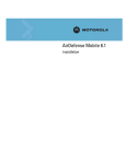
User Guide
Advanced Network Survey Tool
Issue 0.2 (Draft)
May 2009
CSurv M-Tek User Guide
Release: 0.2
Publication: 3gf-2009-01
Document status: Draft
Document release date: 18th May 2009
Copyright © 2009 3g Forensics Limited
All Rights Reserved.
Printed in the United Kingdom.
LEGAL NOTICE
3g Forensics Limited cannot and does not guarantee the accuracy, validity,
timeliness or completeness of any information or data being made available to
you in this document. 3g Forensics and its affiliates and their respective
directors, officers and employees will not be liable or have any responsibility
of any kind for any loss or damage that you incur in the event of any act or
omission in the information in this document, or from any other cause relating
to your access to, inability to access, or use of the information contained in
this document.
Information furnished is believed to be accurate and reliable. However, 3g
Forensics Limited assumes no responsibility for the consequences of use of
such information. Specifications mentioned in this publication are subject to
change without notice and do not represent a commitment on the part of 3g
Forensics Limited.
This publication supersedes and replaces all information previously supplied.
All brand names are trademarks of their respective holders.
Attention
For information about the software licence, please refer to
“Software Licence” section in this document
CSurv M-Tek User Guide
2
Table of Contents
Software Licence............................................................................. 8
3g Forensics Limited software license agreement ..................................................................... 8
Introduction................................................................................... 10
Before you begin..................................................................................................................... 10
Terminology ............................................................................................................................ 11
How to get Help ...................................................................................................................... 11
Support Forum.................................................................................................................... 12
Technical Support ............................................................................................................... 14
Training .......................................................................................................................... 14
Overview ........................................................................................ 15
Introduction ............................................................................................................................ 15
A Brief Guide to Cell Site Analysis ........................................................................................... 16
Background......................................................................................................................... 16
Location Based Survey........................................................................................................ 18
Total Coverage Survey........................................................................................................ 19
Cellular Network Topology Overview .................................................................................. 20
Cellsite Analysis - Why do it? .................................................................................................. 22
CSurv M-Tek Overview............................................................................................................ 23
Wi-Fi - Overview ..................................................................................................................... 24
Wi-Fi - Overview ..................................................................................................................... 24
WI-FI Terminology.............................................................................................................. 24
802.11 Standards................................................................................................................ 25
Channels .......................................................................................................................... 25
Types of Frames ................................................................................................................. 26
CSurv M-Tek Forensic Application ........................................................................................... 28
Getting Started.............................................................................. 29
Inputs and Outputs ................................................................................................................. 29
Installation..................................................................................... 31
CSurv M-Tek ........................................................................................................................... 31
AirPcap ................................................................................................................................... 33
Wi-Spy Installation .................................................................................................................. 34
CSurv M-Tek Configuration and Supporting Files................... 38
2G Configuration File............................................................................................................... 38
[Files] ................................................................................................................................... 40
3G Configuration File............................................................................................................... 40
Supporting Files ...................................................................................................................... 41
Network.txt - Mobile network codes ................................................................................... 41
Countries.txt - Mobile country codes................................................................................... 41
CSurv M-Tek 2G Software ........................................................... 42
Major Features.................................................................................................................... 42
The CSurv M-Tek 2G Environment .......................................................................................... 43
CSurv M-Tek 2G Toolbars ................................................................................................... 44
The playback bar ................................................................................................................ 44
The View Filter Sidebar ....................................................................................................... 45
Making a Drive Survey ........................................................................................................ 47
The Spectrum Graph........................................................................................................... 49
Creating Profiles.................................................................................................................. 51
Network Scan...................................................................................................................... 53
Coverage survey ................................................................................................................. 56
Data logging and CSurv's log files ........................................................................................... 57
CSurv M-Tek User Guide
3
How CSurv logs data........................................................................................................... 57
Preserving channel history .................................................................................................. 57
The log files ............................................................................................................................ 58
Network Scan Data Format ................................................................................................. 58
Spectrum Scan Data Format ............................................................................................... 58
CSurv M-Tek 2G Mapping........................................................................................................ 60
Survey Map Controls ........................................................................................................... 61
CSurv M-Tek 3G Software ........................................................... 65
Major Features.................................................................................................................... 65
3G Mapping Applications............................................................. 67
AirPcap Operation......................................................................... 71
How AirPcap Adapters Operate ............................................................................................... 71
Multiple Channel Capture .................................................................................................... 71
Configuring the Adapters: the AirPcap Control Panel .............................................................. 72
Identifying the AirPcap Adapters......................................................................................... 72
Settings .......................................................................................................................... 73
WEP Keys .......................................................................................................................... 74
AirPcap and Wireshark ............................................................................................................ 75
Identifying the AirPcap ....................................................................................................... 76
The Wireless Toolbar .......................................................................................................... 76
The Wireless Settings Dialog............................................................................................... 78
The Decryption Keys Management Dialog........................................................................... 79
Wi-Spy Operation.......................................................................... 81
Site Survey.............................................................................................................................. 81
Analysing Network Data.......................................................................................................... 82
Display Views...................................................................................................................... 82
Identifying 2.4 GHz band Signatures .................................................................................. 84
Troubleshooting ............................................................................ 86
Wi-Spy Signatures................................................................................................................... 86
Appendix......................................................................................... 88
Appendix A: 802.11 Frequencies & Frames............................................................................. 88
2.4GHz Band....................................................................................................................... 88
5GHz Band.......................................................................................................................... 88
Types of Frames ................................................................................................................. 89
To transmit Raw 802.11 Frames on Your Network ............................................................. 90
Further WireShark Information ............................................................................................... 90
Appendix B: Wi-Spy Keyboard Shortcuts: ............................................................................... 92
Appendix C: Signal Strength ................................................................................................... 93
A note on signal strength indication........................................................................................ 93
Glossary .......................................................................................... 94
CSurv M-Tek User Guide
4
List of User Procedures
Procedure
Procedure
Procedure
Procedure
Procedure
Procedure
Procedure
Procedure
Procedure
Procedure
Procedure
Procedure
Procedure
Procedure
Procedure
Procedure
Procedure
Procedure
Procedure
1 - Setting Up Hardware ................................................................ 29
2 - CSurv M-Tek Installation .......................................................... 31
3 - AirPcap Driver Installation........................................................ 33
4 - Wireshark Analyzer Installation................................................ 34
5 - Wi-Spy Software Installation .................................................... 34
6 - Playing back historical data...................................................... 44
7 - Starting a Spectrum Scan......................................................... 46
8 - Making a Drive Survey ............................................................. 47
9 - Creating and saving profiles..................................................... 51
10 - Starting a Network Scan......................................................... 53
11 - Logging the coverage of a specific channel ........................... 56
12 - Mapping Historical Playback ................................................... 62
13 - Mapping Real Time playback – Spectrum Scan ..................... 63
14 - Mapping Real Time playback – Network Scan ....................... 64
15 - Performing a 3G Network Scan .............................................. 65
16 - Mapping Historical 3G Data.................................................... 69
17 - Mapping Real Time playback.................................................. 70
18 - Performing Initial WI-FI Site Survey ...................................... 81
19 - Performing WI-FI Site Analysis .............................................. 85
CSurv M-Tek User Guide
5
List of Figures
Figure
Figure
Figure
Figure
Figure
Figure
Figure
Figure
Figure
Figure
Figure
Figure
Figure
Figure
Figure
Figure
Figure
Figure
Figure
Figure
Figure
Figure
Figure
Figure
Figure
Figure
Figure
Figure
Figure
1 - Growth of mobile voice volumes 2006-2007*................................ 15
2 - Cellular Network “cells” .................................................................. 17
3 - GSM Network Topology Key Elements ........................................... 20
4 – Wi-Fi network topology.................................................................. 24
5 - Rear view of CSURV M-Tek ............................................................ 29
6 - CSurv M-Tek 2G Configuration File ................................................ 38
7 - COM port numbers in Windows Device manager........................... 39
8 - The playback bar ............................................................................ 44
9 - The view filter side bar................................................................... 46
10 – Spectrum graph ........................................................................... 49
11 - Tabs displaying different profiles ................................................. 51
12 - Network Scan Options .................................................................. 54
13 - An O2 network scan showing Cells available ............................... 55
14 - Display Cell ID Colour List Option ................................................ 61
15 - 3G Network Analyser Software..................................................... 66
16 - Monitor info window ..................................................................... 68
17 - Drawing Polygons from Search Parameters ................................. 68
18 - AirPcap Control Panel ................................................................... 72
19 - Configurable settings within the AirPcap Control Panel ............... 73
20 - Encryption key configuration for WEP.......................................... 75
21 - Wireless interfaces available for capture...................................... 76
22 - Wireshark launched “in-context” .................................................. 77
23 - Advanced Wireless settings .......................................................... 78
24 - Decryption mode .......................................................................... 80
25 - Spectral View ................................................................................ 83
26 - Topographic View ......................................................................... 83
27 - Planar View................................................................................... 84
28 - Timeframe (Locked) ..................................................................... 84
29 - Matching known signatures.......................................................... 86
CSurv M-Tek User Guide
6
List of Tables
Table 1 - Channel colour codes....................................................................... 50
Table 2 – Signal strength to mobile phone bar correlation ............................ 93
CSurv M-Tek User Guide
7
Software Licence
This section contains the 3g Forensics Limited software license.
3g Forensics Limited software license agreement
This Software License Agreement ("License Agreement") is between
you, the end-user ("Customer") and 3g Forensics Limited. PLEASE
READ THE FOLLOWING CAREFULLY. YOU MUST ACCEPT THESE
LICENSE TERMS IN ORDER TO DOWNLOAD AND/OR USE THE
SOFTWARE. USE OF THE SOFTWARE CONSTITUTES YOUR
ACCEPTANCE OF THIS LICENSE AGREEMENT. If you do not accept
these terms and conditions, return the Software, unused and in the
original packaging, within 30 days of purchase to obtain a credit for the
full purchase price.
The "Software" is owned or licensed by 3g Forensics Limited and is
copyrighted and licensed, not sold. Software consists of machinereadable instructions, its components, data, audio-visual content (such
as images, text, recordings or pictures) and related licensed materials
including all whole or partial copies. 3g Forensics Limited grants you a
license to use the Software only in the country where you acquired the
Software. You obtain no rights other than those granted to you under
this License Agreement. You are responsible for the selection of the
Software and for the installation of, use of, and results obtained from
the Software.
1. Licensed Use of Software. Software is furnished for use with
designated hardware or Customer Furnished Equipment ("CFE");
Customer is granted a nonexclusive license to use Software only on
such hardware or CFE, as applicable. Software contains trade secrets
and Customer agrees to treat Software as confidential information
using the same care and discretion Customer uses with its own similar
information that it does not wish to disclose, publish or disseminate.
Customer will ensure that anyone who uses the Software does so only
in compliance with the termsof this Agreement. Customer shall not a)
use, copy, modify, transfer or distribute the Software except as
expressly authorized; b) reverse assemble, reverse compile, reverse
engineer or otherwise translate the Software; c) create derivative
works or modifications unless expressly authorized; or d) sublicense,
rent or lease the Software. Licensors of intellectual property to 3g
Forensics Limited are beneficiaries of this provision.
Upon termination or breach of the license by Customer or in the event
designated hardware or CFE is no longer in use, Customer will
promptly return the Software to 3g Forensics Limited or certify its
destruction.
CSurv M-Tek User Guide
8
2. Warranty. Except as may be otherwise expressly agreed to in
writing between 3g Forensics Limited and Customer, Software is
provided "AS IS" without any warranties (conditions) of any kind. 3g
Forensics Limited DISCLAIMS ALL WARRANTIES (CONDITIONS) FOR
THE SOFTWARE, EITHER EXPRESS OR IMPLIED, INCLUDING, BUT
NOT LIMITED TO THE IMPLIED WARRANTIES OF MERCHANTABILITY
AND FITNESS FOR A PARTICULAR PURPOSE AND ANY WARRANTY OF
NON-INFRINGEMENT.
3. Limitation of Remedies. IN NO EVENT SHALL 3g Forensics
Limited OR ITS PARTNERS OR SUPPLIERS BE LIABLE FOR ANY
OF THE FOLLOWING: a) DAMAGES BASED ON ANY THIRD PARTY
CLAIM; b) LOSS OF, OR DAMAGE TO, CUSTOMER’S RECORDS,
FILES OR DATA; OR c) DIRECT, INDIRECT, SPECIAL, INCIDENTAL,
PUNITIVE, OR CONSEQUENTIAL DAMAGES (INCLUDING LOST
PROFITS OR SAVINGS), WHETHER IN CONTRACT OR
OTHERWISE (INCLUDING NEGLIGENCE) ARISING OUT OF YOUR USE
OF THE SOFTWARE, EVEN IF 3g Forensics Limited,
ITS PARTNERS OR SUPPLIERS HAVE BEEN ADVISED OF THEIR
POSSIBILITY. Some jurisdictions do not allow these limitations or
exclusions and, in such event, they may not apply.
4. General
1. If Customer is the United States Government, the following
paragraph shall apply: All 3g Forensics Limited Software available
under this License Agreement is commercial computer software and
commercial computer software documentation.
2. Customer may terminate the license at any time. 3g Forensics
Limited may terminate the license if Customer fails to comply with the
terms and conditions of this license. In either event, upon termination,
Customer must either return the Software to 3g Forensics Limited or
certify its destruction.
3. Customer is responsible for payment of any taxes, including
personal property taxes, resulting from Customer’s use of the
Software.
Customer agrees to comply with all applicable laws including all
applicable export and import laws and regulations.
4. Neither party may bring an action, regardless of form, more than
two years after the cause of the action arose.
5. The terms and conditions of this License Agreement form the
complete and exclusive agreement between Customer and 3g
Forensics Limited.
6. This License Agreement is governed by the laws of England and
Wales.
Terms will be signed off by 3gforensics legal advisors.
CSurv M-Tek User Guide
9
Introduction
CSurv M-Tek “Cell Survey Multi Technology” is a comprehensive tool for
recovering network data “off air” from the radio spectrum used for the
provision of mobile communications services. The primary role of CSurv MTek is to harvest accurate and real-time data from the networks providing
mobile communications services, GSM, UMTS & Wi-Fi. Through decoding and
understanding this data the CSurv M-Tek operator is able to map the
availability of mobile communications services in a highly accurate manor
specific to a location of interest.
Primarily a forensic tool designed for digital investigators, CSurv M-Tek gives
its operator an insight into the coverage of networks and the infrastructure
that manages user traffic. Paired with internal GPS and a mapping solution
CSurv M-Tek enables the recording of location and network information for
post survey scrutiny.
Described as ‘mapping the DNA of the network’, mobile communications
network surveying allows a forensic examiner to understand a network’s vast
and sophisticated radio frequency topography and therefore predict where
voice or data connections may have been initiated, received, handed off and
also the likelihood of these events taking place.
As network operator coverage maps are largely based on theoretical
assumptions derived from equipment specifications, CSurv M-Tek provides an
actual and real-time view of the network, which is constantly altered by everchanging environmental conditions.
Providing the ability to harvest data from the most common publicly
accessible radio networks GSM, UMTS & Wi-Fi CSurv M-Tek is a most
comprehensive, compact tool in the forensic examiners armoury.
This guide describes:
• How to install and start the CSurv M-Tek software
• How to customise the .INI files for 2G and 3G operation
• How to execute various user procedures to undertake a full network
analysis
• How to perform deeper analysis on WI-FI technologies with packetcapture and spectrum analysis
• How to identify and resolve some common operational issues that can
occur when running CSurv M-Tek software.
Before you begin
This guide is intended for users with the following background:
• Basic knowledge of mobile and Wireless network technologies
• Familiar with networking concepts
CSurv M-Tek User Guide
10
•
•
Basic knowledge of mobile network topologies
Experience with Microsoft Windows and graphical user interfaces (GUI)
Users should also have made available an appropriate PC with the following
minimum requirements:
Windows XP SP2 or above.
500Mb available RAM
2GB free hard drive space
USB 2.0 support
800x600 VGA screen
Pentium 4 processor
CSurv M-Tek comprises:
CSurv M-Tek Unit
UMTS Antenna
GSM / GPS Antenna
2.4Ghz Antenna (WiSpy)
2.4Ghz Antenna (AirPCap)
PSU
Option1 - 90-240V in 5VDC out
Option2 - 12VDC MUPS450
CSurv / PC USB Cable
2 X Mini SIM adapters
CD ROM containing CSurv M-Tek Software and drivers
Upon receipt and before each deployment CSurv M-Tek should be checked to
ensure that:
The CSurv unit does not rattle and no loose parts are evident
The card apertures on the front of the unit are not obstructed, no
debris or broken cards are evident
Antenna plugs are securely affixed and do not rotate freely on the
associated cable.
Sockets on CSurv unit are secure and do not rotate freely.
Terminology
A range of terminology is discussed in this User Guide. Please consult the
Glossary section of this document for a quick reference guide as to a
definition of key terms used.
How to get Help
If you purchased CSurv M-Tek directly from 3gforensics you can contact us
via the 3G Forensics web site:
CSurv M-Tek User Guide
11
www.3gforensics.co.uk
Files and general documents are available without registration. Access to the
support forum is restricted and registration is required.
Support Forum
The support forum provides an invaluable resource for forensic examiners
comprising further product-related hints and tips as well as discussions on
forensic application. The forum will exist as an information ecosystem to
share and disseminate valuable information between professional users of
3gforensics products. Users will also get the opportunity to ask specific
technical questions themselves as well as view previous responses to queries
from other users.
3gforensics ensures anonymity for the forum users if desired and selecting a
nondescript username is permitted. Initial registration is required to confirm
the identity of the user; however 3gforensics does not share this information
with any third parties.
To Register and subsequently gain access the support Forum select the link
Support > Forum as shown below:
CSurv M-Tek User Guide
12
To access the forum for the first time you will need to complete a short
registration. Click on Register to commence this process:
Please follow the on-screen instructions to complete the registration:
CSurv M-Tek User Guide
13
If you purchased CSurv M-Tek from a channel partner/distributor then contact
them in the first instance for initial support.
So far as 3G Forensics is aware the information in this document is correct. If,
however, you discover any errors or have comments regarding the
presentation of the content, please send details by email to:
[email protected]
Technical Support
3G Forensics provides a comprehensive technical support service for its
customers. The 3G Forensics Service Desk may be contacted at any time on
the following numbers:
United Kingdom
Telephone: 01353 749990
Fax within the United Kingdom: 01353 749991
International
Telephone: +44 1353 749990
Fax: +44 1353 749991
Training
For training on CSurv M-Tek we offer full comprehensive product training. We
are
also
pleased
to
be
partnered
with
First
Forensics
(www.firstforensics.com) who can undertake bespoke training covering all
aspects of mobile forensic survey and analysis.
Course Modules include:
•
•
•
•
•
•
•
•
•
Basic network principles
2G (GSM) - 3G (UMTS) & Wi-Fi (802.11) network technologies
Setting up and using CSurv M-Tek
Understanding and interpreting CSurv log files
Worked examples of Network surveys
Using Mapping software for presenting data
Performing 802.11 packet capture
Using the spectrum analyser to visualise wireless transmissions
Basic Cell Site Analysis courtroom skills.
Visit http://www.3gforensics.co.uk/services/training/csurv-training
for more information on training available and proposed scheduled courses.
CSurv M-Tek User Guide
14
Overview
This section briefly details the technologies and applications associated with
CSurv M-Tek.
Introduction
Recent studies and polls are clearly pointing to a continued trend of migration
to mobile communications. The bulk volume of mobile calls are increasing
whilst fixed landline calls are decreasing. Also, as costs are becoming less
prohibitive, the average duration of mobile calls is also increasing.
Figure 1 - Growth of mobile voice volumes 2006-2007*
*Source: IDATE / industry data / Ofcom
As technology advances and mobile communications become more and more
of an integral part of everyday life, cell site analysis has become vital in
serious crime investigations. It is therefore important to the courts that the
technologies behind cell site analysis are understood and the limitations are
considered.
Advances in wireless technologies are creating new areas for investigation.
Home Wi-Fi, Bluetooth and even femtocells are being used to create personal
networks for communication and therefore the sphere of mobile forensics is
ever expanding.
CSurv M-Tek User Guide
15
A Brief Guide to Cell Site Analysis
The following is a brief introduction to cell site analysis and how it is useful in
forensic investigations. This text is not intended to serve as comprehensive
training and only seeks to give a cursory introduction to Cell Site survey
techniques.
Cell site analysis is the procedure of gathering and analysing off air data
transmitted by base station equipment. In conjunction with other relevant
information, the total coverage area and most likely useable coverage are of
any single cell or groups of cells within the network topography may be
established. The resulting conclusions may lead to the establishment of a
mobiles likely location when communicating with a base station within the
network topography. The ultimate conclusion may lead to the generation of a
statement that a mobile phone was (or was not) present at a geographical
location at a specific point in time.
Background
Mobile equipment, operating within modern cellular infrastructure, are radio
transceivers that use complex modulation techniques, to pass large amounts
of data, using relatively low power. In the context of Cell Site Analysis, the
important point to note is that, regardless of the complex services they deliver
to the end user, modern mobile telephones are radio transmitters and
receivers. Radio transmitters and receivers make use of radio waves to
transfer information through space, the way in which radio waves behave
when moving through space is termed 'Propagation'.
Mobile networks are commonly referred to as 2G or 3G networks. 2G
networks are built on the GSM standard (Global System for Mobile
communications) and 3G networks evolved out of 2G networks to provide
additional functionality such as video calls and high speed data. 3G networks
operate on UMTS (Universal Mobile Telecommunications System). Essentially,
cell site analysis is a process of measuring and documenting actual
propagation from transmitters within a communications network and linking
that information to data recovered from those transmissions that uniquely
identify the transmitter.
Mobile phone networks are referred to as ‘Cellular’ networks because they
operate using a cell-like structure. A base station (or cell site) forms the core
of the cell and a mobile phone communicates with cells in the immediate
vicinity to connect to the network. The Figure below illustrates how an ideal
cellular network is made up.
CSurv M-Tek User Guide
16
Figure 2 - Cellular Network “cells”
A cell site typically consists of multiple transmitter receiver pairs, associated
control equipment and antenna. Each set of transmitter receiver pairs will
normally have a unique identity or CellID. Though more complex
configurations can be employed, a typical cell site might consist of three
transmitter receiver sets referred to as Base Stations, each with a unique
CellID, each feeding an antenna.
Cell Site antenna can direct radio waves in a particular direction and by
careful design, limit the spread of the radio waves, effectively limiting the
range and area over which the base station is said to 'cover'. Such an area is
referred to as a 'Sector' Normally each sector is served by a base station and
since each base station has a unique identity 'CellId' the area of coverage,
'sector' can be referred to by the unique CellId.
Base stations are rarely at the centre of the coverage area 'sector', more
often they will be located on one side of the sector. A base station site may
consist of more than one base station and associated antenna, configured to
give coverage to a geographic area. The base station site maybe located near
the geographic centre of the total coverage area of the site.
When a mobile telephone is switched on, it carries out many complex tasks,
to ensure that it connects to the correct network and provides the user with
the best service. One of the most basic of tasks that the mobile telephone
must carry out is to 'look' for a radio frequency carrying information that will
allow the mobile telephone to connect to a valid network and further to
authenticate its self with the network, such that the mobile becomes part of
the network, enabling it to make and receive calls and provide the user with
the services they expect.
The mobile will exchange data with the network using an assigned radio
channel during a process called 'registration' and after the required
registration and authentication sequences have been successfully completed,
the mobile is connected to the network. This whole process takes a very short
time and results in the mobile being connected via a specific Base station and
thus a specific unique CellId.
CSurv M-Tek User Guide
17
During use the mobile may move from one cell site to another, the mobile
and network co-ordinate this by the evaluating radio frequency signal level
and the resulting quality of service. The network operator keeps track of the
mobile to ensure that it can always route calls and services. The network
stores the data related to the mobile point of connection to the network. The
data stored by the network will consist of data unique to the mobile
equipment, including the CellId of the serving base station and the time and
date of calls made/received etc. These logs are referred to as the call data
records or CDR’s.
Network operators record detailed call records for billing purposes, the data
available to a network includes, but is not limited to, date, call length,
inbound, outbound, voicemail, CellID of the serving cell, location of serving
cell. Network operators also have detailed information related to the location
of their cell sites and the associated antenna configurations.
It is reasonable to assume that based on the operators knowledge of a
mobiles activity within its network, the operator could locate the mobile to
within a few meters or tens of meters at any time. This is the case for mobiles
being tracked in real time. However where a mobiles location needs to be
verified based on historical records, or where a mobile user claims to be
somewhere, other than where network data might place them, further more
detailed network coverage data can help verify the mobiles location.
From a mobile operators call data records we can establish the Unique ID of
the cell site that a mobile was connected to when sending or receiving data
to/from the network. The network data may also provide information on the
antenna configuration and possibly even estimated coverage of that base
station/antenna. From this data we might assume the mobile to have been
within the coverage area designated by the network at a particular time.
However the network coverage estimates are usually predictions and are
often limited to coverage related to quality of service rather than actual
coverage. This is especially relevant when the mobile is on the periphery of a
predicted coverage estimate.
It is therefore necessary to perform a detailed site survey using equipment
such as CSurv M-Tek to determine the coverage more accurately.
Location Based Survey
To establish the base station transmitter receiver pair that is providing service
to a specific location, it is necessary to survey that location with equipment
that is capable of receiving and logging the signals propagated by all base
stations on a the network of interest or even all networks that cover that site,
regardless of the signal strength or quality of service offered by those base
stations. Once that data has been collected, best serving cell calculations can
CSurv M-Tek User Guide
18
be carried out to determine exactly which base stations a mobile would use if
at that location.
Note: if on the periphery of coverage, or at a location that has particularly
unusual radio frequency characteristics, a mobile may use more than one
base station, switching between two or three in quick succession. The
protocols used to provide good quality of service, allow for this type of
situation and special algorithms are used to ensure that the mobile does not
flit back and forth rapidly. In practice a mobile is likely to use a particular
base station at any given location. It is commonly accepted that when
surveying, the highest six received signals are decoded and used to identify
potential serving base stations.
In this way, the best serving cell for a particular location can be established.
Secondary and Tertiary serving cells can also be established as can the likely
hood of those alternate cells being used when sending or receiving data. This
information can be used, along with the Network call data records, to
establish the likely hood of a mobile being at or near a specific location at a
particular time.
Of course, the mobile could be anywhere within the coverage area of the
CellId relating to the best serving cell, the technique does not pace the mobile
at a specific location. However it does place the mobile within the coverage
area of the CellId noted on the call data records.
At this point we have a mobile linked to a CellId, by call data records. We
have also established that the CellId is that of a base station whose radio
frequency propagates over a specific location with such strength and quality
that is can be determined to be the best serving base station and thus the
one that is most likely to be used by a mobile operating at that location.
Total Coverage Survey
Let us assume that the user of the mobile in question, states that they were
many kilometres away from the location of interest. To verify the viability of
this possibility, we would need to carry out a survey that will identify:
a) The best serving base station, CellID, at the location that the mobile
user states they were located.
b) A survey that establishes the periphery of coverage by the base
station that the call data records show was in use.
We are seeking to identify the actual coverage of the base station that the
call data records show was in use. We need to establish whether it extends to
the location that the mobile user states they were at the time in question. To
CSurv M-Tek User Guide
19
achieve this we need to use equipment that will allow us to monitor the
extent of coverage provided by one single base station with a given CellId. It
would necessary to travel the respective distances and gather data related to
radio frequency signal from that base station. The signal should be monitored
until it drops below a predetermined level or ceases to exist at all.
Cellular Network Topology Overview
It is important in cell site analysis investigations to understand the
architecture of a cellular network and where evidence can be obtained.
Figure 3 - GSM Network Topology Key Elements illustrates the basic
architecture of a mobile phone network. The mobile phone handset is
referred to as the mobile station (MS). This MS consists of a mobile phone
handset and a SIM (Subscriber Identity Module) card.
The SIM card contains information regarding the network and subscriber
details as well as having memory for storing personal details, such as contact
and SMS messages.
Authentication
Centre
Base
Transceiver
Station
Base Station
Controller
Equipment Identify
Register
Mobile Switching
Centre
PSTN Network
Phone
Mobile
Phone
Base
Transceiver
Station
Base Station Sub-System
Visitor Location
Register
Home Location
Register
Network Sub-System
Figure 3 - GSM Network Topology Key Elements
Base Transceiver Stations (BTS) use radio signals to connect mobile
phones to the network, enabling people to send and receive calls, texts,
emails and MMS. Base Transceiver Stations comprise three main elements:
•
•
An antenna (or several antennas) to transmit and receive radio signals.
These are typically between 0.5 and 2.5 metres long
A supporting structure such as a mast or building to secure the
antenna(s) in a prominent position
CSurv M-Tek User Guide
20
•
Equipment to power the base station and radio equipment, which is
housed in protective cabinets.
Base Transceiver Stations in a cellular network are aggregated to a Base
Station Controller (BSC), which is essentially the “intelligence” of the
network. The BSC handles allocation of radio channels; receives timing
measurements from the mobile phones and controls handovers from BTS to
BTS. The system consisting of the base station controller and its connected
base stations is collectively called the Base Station Subsystem (BSS).
Finally, the Base Station Controllers are themselves physically connected to
the Mobile Switching Centre (MSC), managed by the telephone network
operator, which connects them to the public telephone network and the
provider network. The MSC belongs to a Network Station Subsystem
(NSS), which is responsible for managing user identities, their location and
establishment of communications with other subscribers.
The MSC is generally connected to databases that provide additional functions
such as:
•
•
•
•
The Home Location Register (HLR) is a database containing
information such as geographical position and administrative
information on each of the subscribers registered in the area of the
switch (MSC).
The Visitor Location Register (VLR) is a database containing
information on users other than the local subscribers. The VLR
retrieves the data on a new user from the HLR of the user's subscriber
zone. This data is maintained as long as the user is in the region and is
deleted when the user leaves or after a long period of inactivity
(terminal off).
The Equipment Identify Register (EIR) is a database listing the
mobile terminals.
The Authentication Centre (AUC) is responsible for verifying user
identities.
CSurv M-Tek User Guide
21
Cellsite Analysis - Why do it?
Currently, as mobile communications are at the hub of everyday life, a mobile
telephone is likely to be involved in almost every situation, not least crime.
Some critics will argue that CellSite Analysis is not an exact science and will
look for perceived flaws in the findings, seeking to discredit them for various
reasons. It is therefore imperative to utilise equipment that provides reliable
survey data under the guidance of a user who has a good understanding of
the principals involved.
Using variations of the Location Based Survey and the Total Coverage Survey,
coupled with sound knowledge of the operating parameters and protocols of
the networks, allow us to clearly identify whether a mobile could or could not
have been at or close to a specific location at specific point in time.
Well structured procedures will lead to the same conclusions time after time
and hence corroborate the integrity of Cellsite Analysis and its accepted
techniques. 3gforensics manufacture and supply equipment which is trusted
and deployed today by both Law Enforcement and independent professionals
alike. Through both 3gforensics and its training partners, comprehensive
training is provided to ensure that users can draw valid, substantiated
conclusions from the data gathered. It is reasonable to assume that any
scene of crime investigation should treat such data (including cell site data)
with the same degree of importance as finger prints and DNA.
CSurv M-Tek User Guide
22
CSurv M-Tek Overview
CSurv M-Tek is a proven forensics network analysis solution available form
3gforensics. After careful, tailored, research and development it has been
designed form ground up to meet the needs of the forensic and law
enforcement environment. It is low cost, easy to use, reliable and fully
supported with training tailored to the needs of its user base.
CSurv M-Tek “Cell Survey Multi Technology” is a comprehensive tool for
recovering network data “off air” from the radio spectrum used for the
provision of mobile communications services. The primary role of CSurv MTek is to harvest accurate and real-time data from the networks providing
mobile communications services, GSM, UMTS & Wi-Fi. By decoding and
understanding this data the CSurv M-Tek operator is able to map the
availability of mobile communications services in a highly accurate manor
specific to a location of interest.
Primarily a forensic tool designed for digital investigators, CSurv M-Tek gives
its operator an insight into the coverage of networks, and the infrastructure
that manages user traffic. Paired with internal GPS, and a mapping solution,
CSurv M-Tek enables the recording of location and network information for
post survey scrutiny.
Described as ‘mapping the DNA of the network’, mobile communications
network surveying allows a forensic examiner to understand a network’s vast
and sophisticated radio frequency topography and therefore predict where
voice or data connections may have been initiated, received, handed off and
also the likelihood of these events taking place.
As network operator coverage maps are largely based on theoretical
assumptions derived from equipment specifications, CSurv M-Tek provides an
actual and real-time view of the network, which is constantly altered by everchanging environmental conditions.
Providing the ability to harvest data from the most common publicly
accessible radio networks GSM, UMTS & Wi-Fi CSurv M-Tek is a most
comprehensive, compact tool in the forensic examiners armoury.
CSurv M-Tek is currently deployed in various countries globally and is trusted
by Law Enforcement and professional consultants alike, to gather data for
comprehensive mobile forensic site surveys.
CSurv M-Tek User Guide
23
Wi-Fi - Overview
WI-FI allows users to connect to a network without the need of cables. Wi-Fi
(or Wireless Fidelity) comprises a set of standards for transmitting data over a
wireless network. This is accomplished through Access Points (or Hot Spots).
Multiple users can connect via an Access Point concurrently. The bandwidth is
normally shared equally for each user. WI-FI is limited by a range of up to
approximately 100m and therefore multiple Access Points can communicate
together to enable roaming and extend the physical reach of the network.
The following diagram depicts a WI-FI network topology:
Mobile Phone
Primary Wireless
Access Point
Laptop
Cable Modem
Internet
Corporate Building
Wireless Access
Point
PDA
Printer
PC / Workstation
Wireless Access
Point
Retail Building
Laptop
Laptop
Figure 4 – Wi-Fi network topology
WI-FI Terminology
The terminology commonly associated with WI-FI networks are as follows:
•
•
Wireless LAN (or WLAN) – WLAN is used to indicate a wireless local
area network, e.g. a network between two or more “stations” that uses
radio frequencies instead of wires for the communication.
Stations - All components that can “connect” to a WLAN are referred
to as stations. Stations fall into one of two categories: access points or
wireless clients.
o Access Points transmit and receive information to/from
stations using radio frequencies. The particular choice of a radio
frequency determines a wireless “channel.” An access point
usually acts as a “gateway” between a wired network and a
wireless network.
CSurv M-Tek User Guide
24
•
•
o Wireless clients can be mobile devices such as laptops,
personal digital assistants (PDAs), IP phones or fixed devices
such as desktops and workstations that are equipped with a
wireless network interface card.
Peer-to-Peer/Ad-Hoc - In some configurations, wireless devices can
communicate directly with each other, without the intermediation of an
access point. This kind of network configuration is called peer-to-peer
or ad-hoc.
Basic Service Set (or BSS) - A BSS is the basic building block of a
WLAN. The “coverage” of one access point is called a BSS. The access
point acts as the master to control the stations within that BSS. A BSS
can be thought of as the wireless equivalent of an IP subnet. Every
BSS has an id called the BSSID, which is the MAC address of the
access point servicing the BSS, and a text identifier called the SSID.
802.11 Standards
WLAN according to IEEE 802.11 is the most common standard for wireless
local area networks. It supports data rates up to 54 Mbps at a range up to
around 100m. Currently, plans are in place to enhance both the range and
data rates for 802.11.
802.11 defines the physical layer and the data-link layer for communication
among wireless devices. The original 802.11 specification was ratified in 1997,
uses the 2.4 GHz frequency band, and allows transmission rates of 1 or 2
Mbps.
•
•
•
•
•
802.11a, ratified in 1999, is an extension of 802.11 that operates at 5
GHz. It supports 8 additional transmission rates: 6, 9, 12, 18, 24, 36,
48 and 54 Mbps.
802.11b, ratified in 1999, is an extension of 802.11 that uses the
same 2.4 GHz frequency band, and supports two additional
transmission rates: 5.5 and 11 Mbps.
802.11g, ratified in 2003, is backward compatible with 802.11b, and
supports the same additional transmission rates found in 802.11a: 6, 9,
12, 5, 18, 24, 36, 48 and 54 Mbps.
802.11i, ratified in 2004, defines an enhanced security mechanism
based on AES.
802.11n, expected to be ratified in 2009 (planned for Q4), is
backward compatible with 802.11a, b, and g, and will operate at 2.4
GHz and optionally 5 GHz. It can potentially support data rates up to
600 Mbps.
Channels
Frequency bands within 802.11 are referred to as channels and stations
communicate using a particular channel.
CSurv M-Tek User Guide
25
•
•
802.11b and 802.11g divide the 2.4 GHz spectrum into 13
channels, beginning with channel 1 and ending with channel 13. The
centre frequency of channel 1 is 2,412MHz; channel 2 is 2,417MHz,
etc. The centre frequencies of adjacent channels are 5 MHz apart. The
bandwidth of each channel is 20 MHz which means that channels may
“overlap.” The commonly-used non-overlapping channels are channels
1, 6, and 13. There is a 14th channel whose centre frequency is 12MHz
above channel 13.
802.11a and 802.11n operate in the 5 GHz range which is divided
into a large number of channels. The centre frequency of channel 0 is
5,000 MHz; the centre frequency of channel 1 is 5,005 MHz.
o As with the 2.4 GHz band, each channel is 20 MHz wide.
802.11n allows for “wide” channels – that is, two adjacent 20
MHz bands (note that the channel numbers of the two adjacent
20 MHz bands are not adjacent) can be used “side-by-side” in
order to be backward-compatible with 802.11a/b/g. The actual
use of the channels, however, depends on the country. For
example, in the USA, the FCC allows channels 1 through 11 in
the 2.4 GHz band, whereas most of Europe can use channels 1
through 13. No matter where you are, you can use AirPcap to
listen on any supported channel. The regulations for the 5GHz
band are much more complex.
Each BSS operates on a particular channel, i.e., the access point and all of the
wireless clients within a BSS communicate over a common channel. The same
channel may be used by more than one BSS, however this can reduce the
overall throughput of the interfering BSSs.
A BSS is formed by wireless clients “associating” themselves with a particular
access point. Naturally, a wireless client will have to “discover” whether there
is an access point within range and its corresponding channel. For this
purpose, access points advertise themselves with “beacon” frames and
wireless clients can (passively) listen for these frames. Another discovery
approach is for the wireless client to send out “probe” requests to see if
certain access points are within range. Following the discovery process,
wireless clients will send requests to be associated with a particular BSS.
Types of Frames
The 802.11 link layer is much more complicated than the Ethernet one. The
main reason is that wireless links have lower reliability compared to the
reliability of wired links, and therefore the 802.11 link layer has features to
reduce the effects of frame loss. For example, every data frame is
acknowledged with an ACK frame. Moreover, the protocol needs to support
access point discovery, association and disassociation, authentication,
wired/wireless bridging, and many other features that are not necessarily
needed in a wired link layer. When capturing on a wireless channel, you will
see three main kinds of frames:
CSurv M-Tek User Guide
26
•
Data frames
•
Control frames
o Acknowledgement
o Request to Send
o Clear to Send
•
Management frames
o Beacons
o Probe Requests / Probe Responses
o Association Requests / Association Responses
o Reassociation Requests / Reassociation Responses
o Disassociations
o Authentications / Deauthentications
Additionally, frame headers may contain Quality of Service (QoS) and High
Throughput (+HTC) information.
The Control frames are used to improve the reliability characteristics of the
link. The establishment of a BSS through the process of discovery and
association is supported by the Management frames, including possible
authentication steps in the process.
For further information prefer refer to the respective Appendix section.
CSurv M-Tek User Guide
27
CSurv M-Tek Forensic Application
CSurv M-Tek provides the forensic examiner with a comprehensive tool kit to
undertake detailed reporting and analysis in a mobile forensic context.
The following is not an exhaustive discussion on the capabilities of CSurv MTek but merely serves as some high level applications.
Using the innovative 2G and 3G network analyser software, the user can
collect valuable network data which can be used to assess geographical
information relating to a mobile handset of particular interest. This
information is gathered in detailed log files which can be readily formulated
into a concise format for the purpose of issuing reports for forensic
investigations. Optional MapPoint plugins can be used to integrate real time
mapping with the CSurv M-Tek software logs and these plugins can also be
used for historical playback.
In addition to this, CSurv M-Tek includes tools for detecting and investigating
WI-FI networks which are becoming more and more prevalent. WI-SPY can
be used to perform WI-FI site analysis, for example, to corroborate whether a
particular Wireless Network could be accessed from a certain location related
to an inquiry.
Using Channelyzer within WI-SPY, the forensic investigator can readily see all
2.4GHz and optionally 5GHz activity in a particular geographical location.
Subsequently, detailed recordings can be made on a particular Wireless
Channel to help provide invaluable information relating to a Wireless Network
of particular interest.
AirPcap can be used to undertake live analysis on a WI-FI network.
Information such as websites or servers being accessed by an individual
Station can be easily gleaned and would form an important part of an overall
forensic case.
Other pertinent information such as IP and MAC addresses can be extracted
from Wi-Fi networks using AirPcap in order to link certain proscribed network
activity to a particular hardware device for use in a forensic investigation.
CSurv M-Tek User Guide
28
Getting Started
Inputs and Outputs
Figure 5 - Rear view of CSURV M-Tek
Procedure 1 - Setting Up Hardware
Step
1
Action
Connect all antennas to the CSurv M-Tek Unit.
Note it is important that all antennas are connected to the unit before
connection to a power supply.
The antennas are colour coded and identified by a label with a textual
description of the functionality.
Ensure that antenna plugs are securely coupled to the socket.
DO NOT over tighten.
Antenna sockets should not rotate when connecting antenna plugs.
CSurv M-Tek User Guide
29
Take care not to over tighten the 2.4Ghz connections, they are prone
to loosen if over-tightened.
2
Connect the USB plug to the CSurv M-Tek unit.
connect the USB lead to the host PC at this stage.
DO NOT
Caution
Do not connect the USB lead to the host PC until all the
software has been installed. For software installation see the
next section
3
Connect the Power supply to an appropriate source, mains,
vehicle supply or auxiliary battery supply.
The CSurv MTek unit will then perform a self test. On successful
completion the ‘Function’ indicator LED will illuminate.
--End--
CSurv M-Tek User Guide
30
Installation
CSurv M-Tek
This section details the Diver and Software installation of CSurv M-Tek.
Procedure 2 - CSurv M-Tek Installation
Step
Action
1
Insert the CSurv M-Tek CD-ROM
2
If the setup program does not automatically start browse to the
CD drive and double click CSurv_Setup. The following welcome
screen will open.
3
Select “Next” and read and agree to the terms of the license
agreement.
4
The proposed installation directory will be displayed. Select
“Next” to install to the default location (recommended) or
select “Browse” to choose another directory.
It should be noted that if the default location is changed, the CSurv
configuration files will need edited manually. For more information on
CSurv M-Tek User Guide
31
editing the configuration files please refer to the “CSurv M-Tek
Configuration and Supporting Files” section.
5
Chose where to install the CSurv M-Tek Shortcuts, or select
Next to accept the default settings.
6
Select Next to install the CSurv M-Tek software.
AirPCap software installation will automatically open when the CSurv software
has been successfully installed. If any errors occur during this installation
procedure please refer to the “how to get help” section.
--End--
CSurv M-Tek User Guide
32
AirPcap
This section details the Driver and Software installation of AirPcap.
Procedure 3 - AirPcap Driver Installation
Step
1
Action
If there is a previous version of AirPcap already installed on your
system, uninstall it. This is done by browsing to
Start > Settings > Control Panel > Add or Remove
Programs > AirPcap software > Remove
2
If the CSurv M-Tek Software was successfully installed in the
previous procedure the following dialogue box should have
automatically opened:
3
Click on “Install drivers” to initiate the installation.
4
Follow the installation instructions.
CSurv M-Tek User Guide
33
5
If prompted allow the installer to install WinPCAP on your host
PC
--End--
Procedure 4 - Wireshark Analyzer Installation
Step
1
Action
If you have a previous version of Wireshark Analyzer already
installed on your system, uninstall it by selecting:
Start > Settings > Control Panel > Add or Remove
Programs > Wireshark Analyzer > Remove
2
The same dialogue box should have remained open from the
previous procedure. Click on “Install the Wireshark Analyzer” to
initiate the installation.
3
Follow the default installation instructions.
--End--
If, for whatever reason, you fail to successfully install this software,
please refer to the “how to get help” section.
Wi-Spy Installation
Procedure 5 - Wi-Spy Software Installation
Step
1
Action
If you have a previous version of Chanalyzer already installed on
your system, uninstall it by selecting:
Start > Settings > Control Panel > Add or Remove
Programs > Chanalyzer > Remove
If the CSurv M-Tek software was successful installed a new directory
was created containing the required installation files. The default
location of this directory is:
C:\Program Files\CSurv\CSurv M-Tek
CSurv M-Tek User Guide
34
2
Navigate to the Wi-Spy folder within this CSurv M-Tek directory.
3
Double click on the Chanalyzer_Installer.3.2.msi file
Note: This installer requires the .NET framework to
be installed. If this is not installed either follow the
prompts to install it or browse to
C:\Program Files\CSurv\CSurv MTek\DotNetfx_2
And run the dotnetfx setup application.
The following dialogue box will appear:-
4
Click on “Next” to initiate the installation.
5
Read the License agreement and select “I Agree”.
CSurv M-Tek User Guide
35
6
The proposed installation directory will be displayed. Select
“Next” to install to the default location (recommended) or
select “Browse” to choose another directory.
7
The installer will now be ready to perform the installation
8
Click “Next” to confirm
9
The installation will take place and you will get the following
confirmation dialog window:
10
Navigate to the Wi-Spy folder within the CSurv M-Tek directory.
11
Double click on the Inssider_Installer.msi file‘
12
Click on “Next” to initiate the installation.
13
The proposed installation directory will be displayed. Select
“Next” to install to the default location (recommended) or
select “Browse” to choose another directory.
14
Read the License agreement and select “I Agree”.
CSurv M-Tek User Guide
36
15
The installer will now be ready to perform the installation.
16
Click on “Next” to confirm
17
Confirmation of successful installation will be displayed.
--End--
If, for whatever reason, you fail to successfully install this software,
please refer to the “how to get help” section to get assistance.
CSurv M-Tek User Guide
37
CSurv M-Tek Configuration and Supporting
Files
This section details the purpose of the CSurv M-Tek configuration files and
the subsequent editing and customisation to ensure correct 2G and 3G
operation.
2G Configuration File
CSurv 2G is configured by way of an ‘INI’ file located in the installation
directory. (Default: C:\Program Files\CSurv\CSurv M-Tek\CSurv\MTek 2G)
To view the CSurv configuration file, browse to the above directory and open
the ‘CSurv M-Tek 2G.ini’ file using a text editor such as Notepad.
Figure 6 - CSurv M-Tek 2G Configuration File
Each section of the configuration file begins with the title in square brackets.
Below is a description of each section and the options that are editable by the
user.
CSurv M-Tek User Guide
38
[Application]
This section details different settings regarding the appearance of CSurv MTek 2G software. These are automatically changed when a profile is saved
within CSurv M-Tek software. It is possible to manually change these
settings, but it is not recommended.
The ‘CurrentFile’ entry identifies the location of the saved spectrum scan
profile, this is automatically updated when the profile is saved from within the
application.
[COM]
This section identifies the COM ports that should be used for GSM and GPS
data.
If there are problems with CSurv not receiving GSM or GPS data these entries
should be checked against the device manager (Start > Settings > Control
Panel > System > Hardware > Device Manager > Ports). As shown in
the figure below:
GPS Port
GSM Port
Figure 7 - COM port numbers in Windows Device manager
[Session]
This entry should not be changed
CSurv M-Tek User Guide
39
[Startup]
This section details the startup options for CSurv 2G. The only entry that
should be changed is CS12 which defines the frequency band being surveyed.
The options are:CS12=
0
1
2
3
for
for
for
for
GSM
GSM
GSM
GSM
900Mhz
900Mhz
850Mhz
850Mhz
+
+
+
+
DCS
DCS
DCS
DCS
1800Mhz
1900Mhz
1800Mhz
1900Mhz
operation
operation
operation
operation
CS14 is related to the reporting of CSurv data and should always be left as
‘1’
[MONI]
This entry should not be changed
[Plugin]
This section determines the location of any external applications that you may
want to launch from the CSurv application graphical interface.
By default the MapPoint applications shipped with CSurv M-Tek will be defined
here and should be accessible from the plugin menu within CSurv M-Tek 2G
software.
[Files]
This section lists the locations of any saved profile CSP files. It will be
updated automatically when a profile is saved from within the CSurv M-Tek
2G Software.
3G Configuration File
CSurv 3G is configured by way of an ‘INI’ file located in the installation
directory. This should not require manual editing.
CSurv M-Tek User Guide
40
Supporting Files
Network.txt - Mobile network codes
Each mobile network has its own unique code to identify it. Because network
structure can change rapidly in some countries as mobile companies evolve
and merge, the network codes are stored in an easily editable text file. It is
recommended that this file is updated by the user on a regular basis.
New entries must be formatted in the same way as the existing ones, on a
separate line with the text giving the network name enclosed in double
quotes and separated from the combined identifying code by a comma. For
example:
23401,"MagicPhone UK"
Note: The first three digits of the network code represent the country in
which the network operates. The final 2 digits represent the network.
Countries.txt - Mobile country codes
These three-digit codes are stored in the file countries.txt located in the
installation directory. It is unlikely that you will need to edit the countries list;
it is provided for CSurv M-Tek's use and for reference when editing the mobile
network codes file.
CSurv M-Tek User Guide
41
CSurv M-Tek 2G Software
This section describes the different features and operation of CSurv M-Tek 2G
Software.
The CSurv M-Tek 2G cell survey tool is a software application that utilises a
Quad Band GSM/PCN scanning receiver, built into the CSurv M-Tek platform.
The tool delivers a comprehensive set of accurate measurements on
GSM/PCN networks. The software tools allow the user to collect off-air data
relating to GSM network coverage and topography. The package provides the
accurate RF measurements needed for forensic examination, whether in real
time or historical analysis.
Major Features
•
•
•
•
•
•
•
Highly configurable bar chart displays voice channel and BCCH data
Maximum signal level and dropped channels can be recorded
Real time display of GPS data
Replay recorded data in real time or accelerated
Data is exported in CSV format for easy integration
Optional audio alarm
BCCH locking allows accurate analysis of specific BCCH ranges
It is assumed that:
Drivers have been installed correctly for the CSurv M-Tek hardware.
Optional - Microsoft MapPoint 2004 or 2006 Europe or USA is installed
and registered. Required only if MapPoint demo plugins are to be
used.
CSurv M-Tek is connected to the PC and powered on
Antenna are connected to CSurv M-Tek and they all have clear line of
sight to sky with at least 45 degree windows available to the GPS/GSM
antenna
For first time operation, the system has been in the above state for at
least 20 minutes
CSurv M-Tek User Guide
42
The CSurv M-Tek 2G Environment
Note that spectrum scan can be used with a SIM card inserted or no card
inserted. If a SIM card is inserted barred networks will be visible, but only the
allowed network will show as green bars.
When you start CSurv M-Tek 2G for the first time, you will see the following
window:
The user should be directed to select view-options and check that both the
GSM and GPS ports are correctly stated. If not reset them, close the
application and restart.
The status bar at the very bottom of the window shows the state of the CSurv
hardware. In the example above, the greyed-out GSM notification indicates
that the hardware has no GSM connection. When you connect and switch on
your CSurv unit these notifications will change.
When you start the CSurv M-Tek 2G software, with the hardware
connected, you will need to select Spectrum Scan or Network Scan to
initiate the system.
It is recommended that a Spectrum Scan is selected to confirm system
operation. Once spectrum scan is selected, the system will begin a
spectrum scan and display the data on screen.
The spectrum scan stops automatically if you switch to Network Scan.
CSurv M-Tek User Guide
43
Note: When changing from network to spectrum scan or spectrum to
network scan there may be a slight delay due to internal processing
that is required to shift between these modes of operation.
CSurv M-Tek 2G Toolbars
The toolbar at the top of the screen provides icons for common operations in
Spectrum Scan mode.
Change the way the graph looks (View > Graph Options)
Change the magnification of the graph
Save view filter settings as a profile (File > Save)
Open a saved profile (File > Open)
Create a new profile (File > New)
The playback bar
The playback bar shown in the figure below is used to replay historical data
from both network and spectrum scans.
Open File button
Figure 8 - The playback bar
Procedure 6 - Playing back historical data
Step
Action
1
Use the 'Open file' button on the left of the Playback bar to
open a log file for playback.
2
Navigate to the folder containing the log file you want to play
back, select it and click OK.
The default locations for log files are:-
CSurv M-Tek User Guide
44
Spectrum Scan log:-
C:\Program Files\CSurv\CSurv M-Tek\CSurv\M-Tek 2G\CSurv
M-Tek 2G SpecLog
Network Scan log:-
C:\Program Files\CSurv\CSurv M-Tek\CSurv\M-Tek 2G\CSurv
M-Tek 2G NetLog
3
The buttons of the playback bar will now become available and
the data can be played back, forwarded, paused etc.
--End--
The log files can be played back at
various speeds. To change the speed
of playback, click the Options button
on the playback bar and select the
desired speed from the pop-up menu.
Note that the Fast Forward and
Rewind buttons are independent from
this menu – the Options menu
selects the speed for ordinary
playback only.
The View Filter Sidebar
The View Filter sidebar allows you to customise which channels are displayed
in the channels graph in Spectrum Scan view and save that configuration for
quick recall in future scans. Figure 9 shows the view filter sidebar.
To view the filter side bar
1
Select View > View Filter
When a spectrum scan begins or when you start playback of a log file, CSurv
displays data in accordance with the currently loaded .csp file as defined in
the configuration file. In most cases the startup display will be set to default
to all channels, including voice channels, barred or unusable BCCHs, and
BCCHs with a low signal level.
CSurv M-Tek User Guide
45
Scan this range of channels. If you are
only scanning a single channel, only data
for that channel will be logged.
Display only BCCHs
Do not display channels whose signal is
not in this level range.
Scan a specific cell. Only data for this cell
will be logged. -1 is the null value.
Scan a specific area code. -1 is the null
value.
Select the country and network to scan.
The network and country list is defined in
the supporting files.
Figure 9 - The view filter side bar
Spectrum Scan
Procedure 7 - Starting a Spectrum Scan
Step
1
Action
Click on the Spectrum Scan button just below the main
toolbar.
CSurv M-Tek User Guide
46
A scan will start and after a few moments the graph will begin to show
channel bars as shown in Figure 10.
If you cannot see the X axis and channel bars on the graph,
use the scrollbar at the side of the window or the Zoom Out
button on the toolbar to make sure the main graph area is
visible in the window.
--End--
Making a Drive Survey
To survey a geographical area for coverage by a particular cell or channel, the
“View Filter sidebar” can be used.
Procedure 8 - Making a Drive Survey
Step
Action
1
Click on the Spectrum Scan button just below the main
toolbar.
2
Select View > View Filter to open the view filter side bar
3
Select the desired Channel Number and Cell ID to monitor.
4
Click Apply
--End--
The Level boxes on the View Filter bar can be used to specify a cut-off point.
If the level in the cell you are interested in falls below that point, CSurv M-Tek
will automatically select the best surrounding cell BCCH and lock to that
instead.
Note: Unless you restrict the ARFCN range, the filter options DO NOT affect
the data saved to the log file. The log file will contain all data so that on
replay you may apply the same or different filters. If you restrict the ARFCN
CSurv M-Tek User Guide
47
range, the log file will contain only data from the range of ARFCN that you
have chosen to scan.
CSurv M-Tek User Guide
48
The Spectrum Graph
CSurv M-Tek displays channel data as a bar graph like the one below:
Figure 10 – Spectrum graph
Bars in the graph are displayed in different colours according to the attributes
of the channel. The table on the next page lists the colours CSurv M-Tek
uses. Voice channels can be excluded from the graph; check the 'Exclude
Voice Channel' check box on the View Filter sidebar and click Apply. The
resulting graphs are much smaller:
CSurv M-Tek User Guide
49
Green
Available BCCH
Blue
BCCH listed as unusable (forbidden) by the operating
network.
Red
Unavailable or barred BCCH (usually indicates low
signal strength)
Forbidden Network when SIM in use
Orange
Grey
Encrypted voice channel
Channel not present during this scan cycle (see
section 5.2)
Ghosted out
Table 1 - Channel colour codes
CSurv M-Tek User Guide
50
To view data about a particular channel, hover the mouse cursor over the
channel. An information window like this one will pop up:
The data shown in this window is identical to what is recorded in the log file
for that channel.
Creating Profiles
A profile is simply a saved filtered view that appears as a new ‘tab’ in the
CSurv M-Tek 2G software
Procedure 9 - Creating and saving profiles
Step
1
Action
Select File > New
A new Tab will appear as shown in the figure below:
Figure 11 - Tabs displaying different profiles
2
Select View > View Filter to open the filter side bar
CSurv M-Tek User Guide
51
3
Apply desired settings. For example, to monitor an individual
network select the particular country and network settings from
the Network settings as shown in Figure 9.
4
Select File > Save As to save the profile.
The location of this .csp file will be recorded in the configuration file
and will open automatically with CSurv M-Tek software.
--End--
CSurv M-Tek User Guide
52
Network Scan
A network scan is a scan which focuses only on channels operated by a
specific network. The network scan follows the same protocols as a mobile
phone, providing data from the ‘point of view’ of a mobile phone camped on
the selected network.
A network scan can be performed using a SIM card inserted into the GSM slot
in the front of the CSurv M-Tek unit. Inserting a SIM card in the GSM slot will
ensure that if the signal is lost the CSurv M-Tek unit will continue to poll for
the home network and register with it when it is available again. The
advantage of using a SIM card is that the unit will behave analogous to a
mobile phone connected to that specific network.
Procedure 10 - Starting a Network Scan
Step
Action
1
It is possible to conduct a network scan with or without a SIM
card. If a SIM card is not be inserted then proceed to step 3.
2
Insert SIM card of network to be monitored.
3
Click on the Network Scan button just below the main toolbar.
The Network Scan screen will open, displaying a message which tells you the
spectrum scan is being terminated. Once the spectrum scan has terminated –
(this can take up-to 2 minutes), CSurv M-Tek 2G begins a new scan and
displays a list of available networks as shown in Figure 12 - Network Scan
Options.
4
Select the network to be surveyed.
CSurv M-Tek User Guide
53
Figure 12 - Network Scan Options
The screen now displays a message “Registering with network”.
CSurv M-Tek User Guide
54
Once the unit has registered with the network, it displays the list of available
cells in the order of preference defined by the network, as shown in Figure 13
Figure 13 - An O2 network scan showing Cells available
The data is recorded in the log file – the default log file location is
C:\Program Files\CSurv\CSurv M-Tek\CSurv\M-Tek 2G\CSurv MTek 2G NetLog\ “date of scan”
--End--
CSurv M-Tek User Guide
55
Coverage survey
Procedure 11 - Logging the coverage of a specific channel
Step
Action
1
Perform a network scan as detailed in Procedure 10 - Starting a
Network Scan
2
Double click the ARFCN (Channel) of interest
The Csurv M-Tek software will revert to a Spectrum Scan view and monitor
the channel selected in the Network Scan view. Observing the Cell ID will
determine the coverage on that channel.
--End--
Note: To end a network scan the equipment should be rebooted. Once
the equipment has carried out a SIMless registration with a network,
the equipment MUST be power cycled in order for the equipment to
clear that registration. If a general spectrum scan is performed after
network scan, without power cycling the equipment only the network
on which the equipment was last registered to will show as available
(Green bars)
CSurv M-Tek User Guide
56
Data logging and CSurv's log files
How CSurv logs data
In spectrum scan mode, CSurv logs data for all channels except in the
following two cases:
Only one channel (BCCH) is being monitored
Only one cell (BSIC) is being monitored
In these cases, CSurv only logs data for that channel or cell. See 'The View
Filter sidebar' section for information about configuring CSurv to track only
one channel or cell.
In Network Scan mode, CSurv logs data only for the channels displayed.
Preserving channel history
Because channels drop in and out, it is possible to configure CSurv to track
the existence of channels even when they are not currently transmitting.
To enable this option
1
Select View > Graph Options and Select Preserve ARFCN
History
When history preservation has been enabled, CSurv will keep a record of
vanished channels for one scan cycle after the channel drops out. Channels
which have dropped out since the last scan will appear on the graph “ghosted
out” - as blank spaces with markers recording their previous maximum signal
level. If the channel is absent for more than one scan cycle, CSurv will stop
tracking it.
CSurv M-Tek User Guide
57
The log files
CSurv stores logged data as csv files. These files can be easily imported into
spreadsheet and database applications.
Network Scan Data Format
Comma by Comma break down of output string:
XXXX-XX-XX, GPS Date (Day/Month/Year)
XX:XX:XX,
GPS Time (Hours:Minutes:Seconds)
xx.xxxxxxx,
Longitude, in Decimal WGS84 standard
xx.xxxxxxx,
Latitude, in Decimal WGS84 standard
x,
GPS Lock 1 = yes 0 = No
xx,
Number of satellites in view
xx.x,
GPS Height Above sea level
xxx,
Country Code
xx,
Network Operator Code
Best Serving Cell (Main Cell)
xx,
BSIC *see note
xxxx,
LAC local area code
xxxx,
CID Cell ID
xxx,
ARFCN Absolute radio Frequency Channel Number,
assigned radio channel
-xx,
Received Signal Strength in dBm
xx,
C1
xx,
C2
x,
TA - * Ignore see note
x,
Number of Neighbour cells reported
Nx (Neighbour cells 1-6)
xx,
BSIC
xxxx,
LAC local area code
xxxx,
CID Cell ID
xxx,
ARFCN Absolute radio Frequency Channel Number,
assigned radio channel
-xx,
Received Signal Strength in dBm
xx,
C1
xx,
C2
Spectrum Scan Data Format
Comma by Comma break down of output string for NON BCCH:
XXXX-XX-XX, GPS Date (Day/Month/Year)
XX:XX:XX,
GPS Time (Hours:Minutes:Seconds)
xx.xxxxxxx,
Longitude, in Decimal WGS84 standard
CSurv M-Tek User Guide
58
xx.xxxxxxx,
x,
xx,
xx.x,
x,
xxxx,
x,
-xx
Latitude, in Decimal WGS84 standard
GPS Lock 1 = yes 0 = No
Number of satellites in view
GPS Height Above sea level
Channel is a BCCH, Y or N
ARFCN Absolute radio Frequency Channel Number,
assigned radio channel
Null
RxLev in dBm
Comma by Comma break down of output string for BCCH:
XXXX-XX-XX, GPS Date (Day/Month/Year)
XX:XX:XX,
GPS Time (Hours:Minutes:Seconds)
xx.xxxxxxx,
Longitude, in Decimal WGS84 standard
xx.xxxxxxx,
Latitude, in Decimal WGS84 standard
x,
GPS Lock 1 = yes 0 = No
xx,
Number of satellites in view
xx.x,
GPS Height Above sea level
x,
Channel is a BCCH, Y or N
xxxx,
ARFCN Absolute radio Frequency Channel Number,
assigned radio channel
xx,
BSIC
-xx,
RxLev in dBm
x.xx,
BER - bit error ratio
xxx,
Mobile Country Code
xxx,
Mobile Network Code
xx,
LAC
xxxxxx,
CELL ID
x,
Cell Status
xx,
numArfcn,<arfcn1>…<arfcn64>
xx,
numChannels,<arfcn1>…<arfcn32>
CSurv M-Tek User Guide
59
CSurv M-Tek 2G Mapping
Within the CSurv M-Tek software it is possible to map the results in both realtime and historically. This section covers the operation of the MapPoint
plugins which are an optional add on to CSurv M-Tek.
Menu Options (Within Map View)
File
− Import GSM Data - Permits the import of GSM (2G) Data from any
saved CSurv 2G log file.
− Import Base Station Data - Permits the import of a .BSS file
containing Base Station location information to be over-laid on the
CSurv map
Options
− Pointer Line Only - Select any push-pin to identify it by number.
− Bubble Text Only - Select any push-pin to display the location and
network data logged at this location.
− Goto the start of GSM Records - Rewinds loaded survey data to the
beginning of the log file.
− Filter Network on Playback… - Allows a network filter to be applied
so that only the data from the selected network is shown during
playback. Filtering is possible by MCC (Country Code) or MNC (Network
Code).
− Cell ID value to monitor… - Allows a specific Cell ID to be
monitored. An audible sound will occur when the monitored Cell ID
falls out of range and will sound again when it becomes available.
− Colour change on Selected Cell ID - Limits push-pin colour change
only for the selected Cell ID.
− Colour Change on Any Cell ID - Enables push-pin colour change for
each new Cell ID
− Display Cell ID Colour List - Displays the push-pin colours used for
each Cell ID (See Figure 14 - Display Cell ID Colour List Option)
CSurv M-Tek User Guide
60
− Suspend Auto Map Update
This option is not
available when Colour
Change on Selected CI
is enabled as only 2
colours are used in this
function, one for the
selected Cell ID and one
for all other Cell ID's.
Figure 14 - Display Cell ID Colour List Option
Survey Map Controls
Stops the survey replay
Replays selected survey data
Shuffles forward one push-pin
Shuffles back one push-pin
Fast Forward survey
Rewind survey
CSurv M-Tek User Guide
61
Procedure 12 - Mapping Historical Playback
Step
Action
To open and view a map from any saved Spectrum or Network Scan,
1
Open the CSurv M-Tek 2G software
Start > Programs > CSurv M-Tek > CSurv
2
To view a saved spectrum scan select
Plugin > Spectrum Scan Map
3
To view a saved network scan select
Plugin > Network Monitor Map
Microsoft Mappoint must be installed to operate the CSurv M-Tek
plugins. The selected plugin will now open.
4
To load data from a saved log file select
File > Import GSM Data…
5
Browse to the location of the .CSV log file to be loaded
Use the Survey map controls, as described on the previous page to ‘replay’
the selected data.
If ‘Bubble Text Only’ is selected any push-pin can be selected to display the
location and network data logged at that particular location.
--End--
CSurv M-Tek User Guide
62
Procedure 13 - Mapping Real Time playback – Spectrum Scan
Step
Action
To view a Spectrum Scan drive survey on the map in real time it is first
necessary to save a profile filter named CSurv_Map.
1
Open the CSurv M-Tek 2G software
Start > Programs > CSurv M-Tek > CSurv
2
Select
File > New
A new tab will now open and the filer view can be used to specify what
channels to survey. This Tab should then be saved as CSurv_Map.csp
File > Save as
3
Select
4
Browse to CSurv directory and save tab as CSurv_Map.csp
5
Select
Plugin > Spectrum Scan Map
The CSurv M-Tek 2G Spectrum Scan Map plugin will now open and data will
be streamed from the CSurv_Map.csp to the mapping software. To view the
details at a particular location ensure Options > Bubble text only is set and
select the pushpin directly on the map.
--End--
CSurv M-Tek User Guide
63
Procedure 14 - Mapping Real Time playback – Network Scan
Step
Action
1
Begin a network scan as described in Procedure 10 - Starting
a Network Scan
2
Once data is being logged select
Plugin > Network Monitor Map
The Network Map application will open and map the network scan data in real
time. To view the details at a particular location ensure Options > Bubble
text only is set and select the pushpin directly on the map.
--End--
CSurv M-Tek User Guide
64
CSurv M-Tek 3G Software
This section describes the various features and operation of CSurv M-Tek 3G
Software.
The CSurv M-Tek 3G cell survey tool delivers a comprehensive set of accurate
measurements on 3G networks. The software tools allow the user to collect
off-air data relating to 3G network coverage and topography. The package
provides the accurate RF measurements needed for forensic examination,
whether in real time or historical analysis.
Major Features
•
•
•
•
•
Reports 3G RF Lev, Cell id's - PSC's - sync list - async list - ec/lo
Logs 3G network drop-out locations
Data is exported in CSV format for easy integration
Real time display of GPS data
Post Data-capture analysis using Microsoft MapPoint
It is assumed that:
Drivers have been installed correctly for the CSurv M-Tek hardware.
Optional - Microsoft MapPoint 2004 or 2006 Europe or USA is installed
and registered. Required only if Mappoint demo plugins are to be
used.
CSurv M-Tek is connected to the PC and powered on
Antenna are connected to CSurv M-Tek and they all have clear line of
sight to sky with at least 45 degree windows available to the GPS/GSM
antenna
For first time operation, the system has been in the above state for at
least 20 minutes
An active SIM card is available for the network to be monitored
Procedure 15 - Performing a 3G Network Scan
Step
Action
1
Insert a SIM card of the network to be monitored, into the
UMTS slot in the front of CSurv M-Tek unit. The SIM card must
be active.
2
Open the CSurv M-Tek 3G Network Analyser software:
Start > Programs > CSurv M-Tek > CSurv M-Tek 3G
Network Analyser
CSurv M-Tek User Guide
65
The 3G network analyser will open and indicate that the 3G hardware is
rebooting, registering with the home network and gathering the data.
--End-Figure 15 shows the 3G network analyser software:
Figure 15 - 3G Network Analyser Software
If 3G network coverage is not available the software will report that the
network has dropped to GSM.
Note: The 2G network scan should be run simultaneously with the 3G
network analyser to allow the user to analyse what Cells a mobile phone may
have been connected to.
CSurv M-Tek User Guide
66
3G Mapping Applications
This section describes the different menu functions of the 3G mapping
application
To open the 3G Mapping application,
1
Open CSurv M-Tek 3G Network analyser (Start > Programs >
CSurv M-Tek > CSurv M-Tek 3G Network Analyser)
2
Select Map Options > Open Map Application
Menu Functions (within Map View)
File
− Import WCDMA Data - Permits the import of UTMS (3G) Data from
any saved CSurv M-Tek 3G log file.
Options
− Suspend Active Map Update - This option should be selected whist
viewing data from a saved log file, as it suspends the active data from
CSurv M-Tek from updating the map. Un-checking this option will
allow the map to be updated with live data from the CSurv M-Tek unit.
− Map Colour Change on PSC Values - Whether using the map
during a survey, or for the subsequent review of any previous survey,
each position where a scan has taken place is represented by a
coloured “Push-Pin”. Selecting this Option will change the colour of
each Push-Pin in relation to the PSC value decoded.
− Map Colour Change on Cell ID Values - As above, except this
alternative option will enable Push-Pin colours to be changed based on
the Cell ID.
− Display Colour List for the Map - Opens a legend indicating the
colours allocated to the PSC/Cell ID values.
− Monitor Selected PSC - The Monitor feature is ideal for single user
operation as it provides an audible indication as you move in and out
of specific conditions. When PSC is selected, CSurv M-Tek will provide
an audible “Bong” when you leave the specified PSC and a “Bing”
when you return to it. This allows a single user to drive throughout the
coverage area of the specified PSC without having to look at the CSurv
Map.
CSurv M-Tek User Guide
67
− Monitor Selected Cell ID - As above, except this alternative option
will enable the Monitor function on a specified Cell ID.
− PSC/Cell ID value to monitor - opens a window, as shown below,
in which the user can select which Cell ID or PSC to Monitor.
Figure 16 - Monitor info window
− Goto the Start of WCDMA Records - rewinds the loaded survey
data to the beginning of the log file.
− Draw Polygon from Search Parameters - Overlays colour coded
polygons onto the map based on selectable search criteria, namely,
Cell ID, PSC or RSCP. The colour is user selectable and may be drawn
as an outline or a solid polygon. Multiple Polygons may be overlaid
over each other.
− Delete Last polygon – deletes last polygon drawn
Delete Last Polygon
Deletes the last Polygon drawn.
Figure 17 - Drawing Polygons from Search Parameters
CSurv M-Tek User Guide
68
Procedure 16 - Mapping Historical 3G Data
Step
Action
To open and view a map from any saved 3G log file,
1
Open the CSurv M-Tek 3G software
Start > Programs > CSurv M-Tek > CSurv M-Tek 3G
Network Analyser
2
Select
Map Options > Open Map Application
Microsoft MapPoint must be installed to operate the CSurv M-Tek plugins.
3
To load data from a saved log file select
File > Import WCDMA Data
4
Browse to the location of the .CSV log file to be loaded
Use the Survey map controls, as described in Procedure 16 - Mapping
Historical 3G to ‘replay’ the selected data.
Any push-pin can be selected to display the location and network data logged
at that particular location.
--End--
CSurv M-Tek User Guide
69
Procedure 17 - Mapping Real Time playback
Step
1
Action
Open the CSurv M-Tek 3G software
Start > Programs > CSurv M-Tek > CSurv M-Tek 3G
Network Analyser
2
Select
Map Options > Open Map Application
--End--
CSurv M-Tek User Guide
70
AirPcap Operation
This section describes the AirPcap operation. AirPcap is essentially a packetcapture tool used for the detailed analysis of wireless communication (Wi-Fi)
networks.
How AirPcap Adapters Operate
The AirPcap adapter captures the traffic on a single channel at a time; the
channel setting for the AirPcap adapter can be changed using the AirPcap
Control Panel, or from the “Advanced Wireless Settings” dialog in Wireshark.
The AirPcap adapter can be set to any valid 802.11a/b/g/n channel for packet
capture.
All of the AirPcap adapters can operate in a completely passive mode. This
means that they can capture the traffic on a channel without associating with
an access point, or interacting with any other wireless device. Unless you are
transmitting with either AirPcap Tx, Ex or Nx, none of the adapters is
detectable by any other wireless station.
The AirPcap adapters can work in, so called, Monitor Mode. In this mode,
the AirPcap adapter will capture all of the frames that are transferred on a
channel, not just frames that are addressed to it. This includes data frames,
control frames and management frames. When more than one BSS shares
the same channel, the AirPcap adapter will capture the data, control and
management frames from all of the BSSs that are sharing the channel and
that are within range of the AirPcap adapter.
The AirPcap software can optionally be configured to decrypt WEP-encrypted
frames. An arbitrary number of keys can be configured in the driver at the
same time, so that the driver can decrypt the traffic of more than one access
point at the same time. WPA and WPA2 support is handled by applications
such as Wireshark and Aircrack-ng.
Multiple Channel Capture
Note: This section applies to all members of the AirPcap Product family
except AirPcap N.
When listening on a single channel is not enough, multiple AirPcap adapters
can be plugged in a PC and used at the same time to capture traffic
simultaneously from different channels. The AirPcap driver provides support
for this operation through to the Multi-Channel Aggregator technology, that
exports capture streams from multiple AirPcap adapters as a single capture
stream.
CSurv M-Tek User Guide
71
The Multi-Channel Aggregator consists of a virtual interface that can be used
from Wireshark or any other AirPcap-based application. Using this interface,
the application will receive the traffic from all the installed AirPcap adapters,
as if it was coming from a single device. The Multi-Channel Aggregator can be
configured like any real AirPcap device, and therefore can have its own
decryption, FCS checking and packet filtering settings.
Configuring the Adapters: the AirPcap Control
Panel
The AirPcap control panel provides a convenient and intuitive way to
configure the parameters of currently-connected AirPcap adapters. The
changes made to an adapter using the AirPcap control panel will be reflected
in all of the applications using that adapter.
To start the AirPcap control panel, click on:
START→PROGRAMS→AirPcap→AirPcap Control Panel
Figure 18 - AirPcap Control Panel
The drop-down list in the Interface box at the top of the panel presents a list
of currently-installed adapters. Selecting one of the adapters in the list allows
you to view/edit its configuration.
Identifying the AirPcap Adapters
The drop-down list identifies the USB AirPcap adapters using adapter
numbers (e.g. 00, 01, …) and does not distinguish between AirPcap Classic,
AirPcap Tx, AirPcap Ex, and AirPcap Nx. Fortunately, the AirPcap adapters
have an Led that can be caused to blink by first selecting the adapter from
CSurv M-Tek User Guide
72
the drop-down list and clicking on the Blink Led button. This feature is useful
in distinguishing among the USB AirPcap adapters when multiple adapters are
plugged into your system and an easy way to associate the physical adapters
with the adapter numbers assigned by the system.
AirPcap N appears as “AirPcap N Wireless Capture Device” in the drop-down
list, making it easy to identify if it is present.
Settings
This sections details the settings configurable via the AirPcap Control Panel.
Figure 19 - Configurable settings within the AirPcap Control Panel
The Basic Configuration box contains the following settings:
Channel: The channels available in the Channel list box depend upon the
selected adapter. Since channel numbers 1, …, 14 in the 2.4GHz and 5GHz
bands overlap and there are centre frequncies (channels) that do not have
channels numbers, each available channel is given by its centre frequency.
Where applicable, the BG or A channel numbers are also given. All of the
channel centre-frequencies supported by the selected adapter will be made
available in the Channel list. The bandwidth of each channel is 20MHz.
Extension Channel: For 802.11n adapters, one can use the Extension
Channel list create a “wide” channel. The choices are -1 (the preceding
20MHz frequency band), 0 (no extension channel), or +1 (the succeeding
20MHz frequency band). The channel of the additional frequency band is
called the extension channel. The Extension Channel list box lets you choose
a valid extension channel (above or below) for a given channel (See Figure
2). Not all channels have above and below extension channels. For example,
BG channels 1, 2, 3, and 4 do not have a -1 (below) extension channel. The
CSurv M-Tek User Guide
73
reason is that the centre frequencies of the primay and extension channels
need to be separated by 20MHz. So if 4 were the primary channel,
channel 1 (which is the lowest BG centre frequency) is only 15 MHz below
channel 4.
Capture Type: 802.11 frames only, 802.11 frames plus radio information
(See Radiotap), or 802.11 frames plus the Per-Packet Information (PPI)
header (See Downloads for the current PPI specification). PPI and radio
information includes additional information not contained in the 802.11 frame:
transmit rate, signal power, signal quality, channel, and (for PPI) multiple
antenna information.
Include 802.11 FCS in Frames: if checked the captured frames will include
the 802.11 4-bytes Frame Check Sequence. This option can be disabled if an
application has difficulty decoding the packets that have the Frame Check
Sequence.
FCS Filter: this drop-down list allows you to configure the kind of Frame
Check Sequence filtering that the selected adapter will perform:
•
•
•
All Frames: the adapter will capture all the frames regardless of
whether the FCS is valid or not.
Valid Frames: the adapter will only capture frames that have a valid
FCS.
Invalid Frames: the adapter will only capture frames that have an
invalid FCS.
Note: AirPcap stores the configuration information on a per-adapter
basis. This means that changing the configuration of an adapter
does not affect the settings of any of the other adapters.
WEP Keys
The AirPcap driver is able to use a set of WEP keys to decrypt traffic that is
WEP encrypted. If a frame is WEP encrypted, the driver will attempt to
decrypt the frame using the user-supplied set of WEP keys – the driver will try
all of the WEP keys for each frame until it finds one that decrypts the frame.
If the decryption is successful, the unencrypted frame is passed to the user
application; otherwise the original frame is passed along. By configuring the
AirPcap driver with multiple WEP keys, it is possible to decrypt traffic coming
from multiple access points that are using different WEP keys, but
transmitting on the same channel.
The list of keys can be edited by selecting the Keys tab in the AirPcap control
panel.
To add or remove a key, use the “Add New Key” or “Remove Key” buttons,
respectively. “Edit Key” allows you to change the value of an existing key.
“Move Key Up” and “Move Key Down” can be used to change the order of the
CSurv M-Tek User Guide
74
keys. This may be an important performance consideration, since the driver
uses the keys in the order they appear in this list.
The currently configured keys are shown in the “Keys” list. It is possible to
turn WEP decryption on and off at any time by using the “Enable WEP
Decryption” check box.
Figure 20 - Encryption key configuration for WEP
The keys are applied to the packets in the same order they appear in the keys
list. Therefore, putting frequently used keys at the beginning of the list
improves performance.
Note: The keys are stored by the AirPcap Control Panel globally. This means
that any keys specified in the list will be used by all AirPcap adapters
(Including AirPcap N).
AirPcap and Wireshark
The user interface of Wireshark is completely integrated with AirPcap. This
increases your productivity, and allows you to get the best from the network
analyzer you are used to.
CSurv M-Tek User Guide
75
Identifying the AirPcap
Adapters in Wireshark shows the Wireshark Capture Interfaces dialog
(Capture_Interfaces). The AirPcap Interfaces are easly identified by icon next
to them.
Figure 21 - Wireless interfaces available for capture
The Wireless Toolbar
The wireless toolbar provides a fast and productive way to set up the most
important wireless capture settings.
When Wireshark starts, the active interface is the default one
(Edit_Preferences_Capture_Default Interface). During Wireshark usage, the
active interface is the last one used for packet capture.
CSurv M-Tek User Guide
76
Figure 22 - Wireshark launched “in-context”
The Wireless toolbar has the following controls:
• 802.11 Channel: allows the user to change the channel on which the
current AirPcap adapter captures. The channel can be changed at any
time, even while Wireshark is capturing.
• Offset: for AirPcap N, allows the user to set an extension, or “wide”
channel.
Tip: When real-time packet updates are enabled
(Edit_Preferences_Capture_Update list of packets in real time),
switching from channel to channel allows you to see which channels
have traffic and which ones are unused.
FCS Filter: allows the user to select which packets the current AirPcap
adapter should capture: all the packets, only packets with a valid FCS,
or only packets with an invalid FCS. This feature can be used to get a
quick check on the quality of the transmission on the channel and/or
the quality of the adapter’s reception.
Decryption mode: can be one of the following:
o None: no decryption is performed, neither at the driver level
nor in Wireshark.
o Wireshark: the driver doesn’t perform any decryption of the
captured packets, and they are decrypted by Wireshark while
displaying them. This has the advantage of minimizing the CPU
load during the capture process. Moreover, the driver doesn’t
manipulate the packets, so the captured data is a precise picture
CSurv M-Tek User Guide
77
of the network traffic. However, capture filters (also known as
BPF filters) on TCP/IP fields or packet payloads will not work.
Since this kind of decryption is done by the analyzer, when you
turn it on or off, you will see the changes immediately reflected
in the Wireshark window.
o Driver: the packets are decrypted by the driver before reaching
Wireshark. This option has two advantages:
capture filters on TCP/IP fields or packet payloads will
work; when logging the network traffic to disk, it will be
unencrypted. This will make it easier for third party
applications to understand them. Since this kind of
decoding is done during the capture, the changes you
make will be effective starting with the next capture.
o Wireless Settings: this button opens the Wireless Settings
dialog for the currently-selected AirPcap adapter.
o Decryption Keys: this button opens the Decryption Keys
Management dialog.
The Wireless Settings Dialog
The Wireless Settings Dialog can be used to set the advanced parameters of
an AirPcap adapter. This dialog can be accessed either from the Wireless
Toolbar (Wireless Settings), or direct from the main menu itself
(Capture_Options_Wireless Settings).
Figure 23 - Advanced Wireless settings
The parameters that can be configured are:
Channel: the channels are specified in terms of their centre
frequencies and the range of channels varies from adapter to adapter.
Channel Offset: set to -1, 0, or +1 for AirPcap N. This allows the use
of “wide” channels.
CSurv M-Tek User Guide
78
Capture Type: 802.11 frames only, or 802.11 frames plus Radio
information (Radiotap header), or 802.11 frames plus the Per Packet
Information (PPI) header. Radiotap and PPI include information such
as, transmit rate, signal power, signal quality, channel, and will be
displayed by Wireshark in the radiotap header of every frame.
Include 802.11 FCS in Frames: if checked the captured frames will
include the 802.11 4-bytes Frame Check Sequence.
FCS Filter: this drop-down list allows to configure the kind of Frame
Check Sequence filtering that the selected adapter will perform:
o All Frames: the adapter will capture all the frames, regardless
of whether the FCS is valid or invalid.
o Valid Frames: the adapter will only capture frames that have a
valid FCS.
o Invalid Frames: the adapter will only capture frames that have
an invalid FCS.
The Decryption Keys Management Dialog
This dialog window can be used to organize the keys that will be used to
decrypt the wireless packets. It is possible to decrypt packets encrypted with
WEP, WPA and WPA2. however, notice that:
In order to decrypt WPA and WPA2 you will need to capture the 4-way
EAPOL handshake used to establish the pairwise transient key (PTK)
used for a session.
Wireshark can only decrypt “WPA personal” sessions, which use preshared keys. Decryption of “WPA Enterprise” sessions is not supported.
As explained in “The Wireless Toolbar” section, there are three possible
decryption modes: None, Driver and Wireshark. The keys specified in this
dialog will be used either by the Driver or Wireshark depending upon the
selected Decryption Mode. It should be noted that WPA and WPA2 are
decrypted only in Wireshark mode.
Note that, no matter which setting is used, the keys are applied to the
packets in the same order they appear in the keys list. Therefore, putting
frequently used keys at the beginning of the list improves performance.
To add or remove a key, use the “Add New Key” or “Remove Key” buttons,
respectively. “Edit Key” allows you to change the value of an existing key.
“Move Key Up” and “Move Key Down” can be used to change the order of the
keys. This may be an important performance consideration, since the driver
uses the keys in the order they appear in this list.
Use the “Select Decryption Mode” drop-down box to switch among the
different decryption modes.
CSurv M-Tek User Guide
79
Figure 24 - Decryption mode
WEP keys are array of bytes of arbitrary length expressed in hexadecimal.
WPA and WPA2 keys can be of two types:
Passphrase (WPA-PWD): This is the Passprase and SSID
combination most often used to configure WPA and WPA2. The
passphrase is a string between 8 and 63 characters in length. The
SSID can be omitted, in which case Wireshark will use the lastseen
SSID on the network. Non-printable characters can be represented by
a “%” character followed by a hexadecimal number for both the
passphrase and SSID. The passphrase and SSID are used to derive
Pre-Shared Key.
Pre-Shared key (WPA-PSK): This allows the user to provide a
binary TKIP or CCMP key (used to derive the temporary key of each
session) which is normally the kind of key returned by tools like
Aircrack. The key is 256 bit long, and is expressed as a hex string (64
characters). A tool to convert a passphrase and SSID into a 256-bit
PSK
can
be
found
on
the
Wireshark
web
site
at
http://www.wireshark.org/tools/wpa-psk.html.
The keys that you specify in this list are global.
To change the channel of any individual adapter, select the
Capture_Options menu item, select the desired interface, click on the Wireless
Settings button and then set the channel value in the channel drop-down box.
CSurv M-Tek User Guide
80
Wi-Spy Operation
As the 2.4 GHz ISM Band becomes more popular (and hence more congested)
interference from WI-FI and non-WI-FI devices can seriously degrade Wi-Fi
performance. Wi-Spy scans and displays all activity in the 2.4 GHz spectrum
and helps to quickly differentiate between interference and defined WI-FI
signals through signature traits.
From a Forensic point of view, Wi-Spy provides analysis as to geographical
range of a particular WI-FI source.
In summary the following data analysis will be offered by Wi-Spy:
Data Analysis
• Current Signal Strength
• Average Signal Strength
• Maximum Signal Strength
• Frequency Marker
• Amplitude Line
Wi-Fi Information
• Amplitude vs Wi-Fi Channel
• Wi-Fi Channel Selector
• Saving Data
• Save Recording
• Play Recording
• Save Image to File
• Print Image
• Copy Image to Clipboard
Site Survey
Wi-Spy will provide detailed analysis of 2.4 GHz band activity for a specific
location. There is no time restriction placed on how long the analysis can run
within Wi-Spy, however other restrictions will apply.
Procedure 18 - Performing Initial WI-FI Site Survey
Step Action
1
Run Chanalyzer for a sustained period to characterise the desired
location for 2.4GHz band activity.
Note: It is recommended to run the analysis for 24 hours to
capture all activity on a daily cycle. However, it may not be always
feasible to perform the analysis for this period due to a number of
factors including continued access to the desired location and
CSurv M-Tek User Guide
81
environmental restrictions.
2
Save the running session to a desired location on your PC by
selecting:
File > Save Recording As
3
Ensure the recording has been successfully saved.
Note: The WI-SPY recording format is *.wrs and will require
approximately 5Mb per hour of recorded data.
4
Optional - Use AirPcap to record live data analysis on a Wi-Fi
channel of interest if deemed appropriate to the site survey
requirements.
--End--
Analysing Network Data
Chanalyzer can show up to 1 hour of data at a time allowing you to quickly
scan through the 24 hour recording. If you have a specific 802.11 channel
that you plan to monitor then change the X-axis labels to Wi-Fi and highlight
that channel to make it easier to spot network activity on that channel.
Chanalyzer also provides an analysis of all (1-11) Wi-Fi channels.
Note: The IEEE 802.11b standard defines 14 channels, although some
channels are not available in certain countries.
Display Views
Spectral View
The Spectral View contains a waterfall graph that shows amplitude over time
for each frequency. Based on the timeframe a row is added to the Spectral
View every X seconds or minutes. The color of each frequency/time
coordinate represents the amplitude of that frequency, with dark blue
representing low amplitudes and bright red representing high amplitudes as
shown in the legend.
Below shows the spectral view:
CSurv M-Tek User Guide
82
Figure 25 - Spectral View
Topographic View
The Topographic View contains amplitude over frequency graph similar to the
Planar View, but instead of showing the current amplitude of each frequency
it shows the popularity of each frequency/amplitude coordinate during the
time displayed. The coloration of the Topographic View is similar to the
Spectral View with blue being low and red being high, but the coloration now
represents the "popularity" instead of the amplitude.
Below shows the Topographic view:
Figure 26 - Topographic View
Planar View
The Planar View shows a typical amplitude over frequency display. The yellow
line shows the current amplitude, the green shows the average amplitude,
and the blue shows the maximum amplitude. Click the Current, Average, and
Max labels in the Planar View controls to toggle the display of the
corresponding trace. You can also press CTRL ALT M, A, or C to turn off the
Max, Average, or Current display.
Below shows the Planar view:
CSurv M-Tek User Guide
83
Figure 27 - Planar View
Timeframe
The timeframe controls how much data is displayed in the views. Each view
(Spectral, Topographic, and Planar) shows a different look at the same data
to help you better visualize your wireless landscape.
Toggling between different lengths of recordings can aid you in your
understanding of shapes of wi-fi activity. You can lock the timeframe by
clicking the lock. Then if needed, adjust the length by grabbing the tail. This
is a great tactic to use while watching a fast frequency hopping device. The
minimum display time is 30 seconds, and you can drag it to show whatever
segment you wish.
Below shows the timeframe:
Figure 28 - Timeframe (Locked)
Tip: For fast frequency hopping devices, a short timeframe works well; for
wi-fi and other devices that do not change channels, longer timeframes tend
to show a better "signature" in the Topographic View.
Identifying 2.4 GHz band Signatures
Chanalyzer provides visualization of your wireless landscape in three
dimensions (frequency, amplitude and time). By utilising all three views in
Chanalyzer most interference signatures can be quickly identified.
With the ever-increasing popularity of Wi-Fi, you are likely to encounter
neighbouring Wi-Fi networks. There are a number of useful tools available to
gather Wi-Fi-specific information, such as InSSIDer. This tool will display the
network name (SSID), channel, signal strength, and type of security. For
more detailed analysis, please use AirPcap in Csurv M-Tek
CSurv M-Tek User Guide
84
The Device Signatures Library is a growing collection of recordings of
common devices that you are likely to encounter. The library can be accessed
via the CSurv section of our web site (see How to get Help Section of this
document).
Features:
• Typical 2.4GHz device signatures are identifiable using the Signatures tool.
• Inspector will display frequency, amplitude and popularity of whatever point
the mouse hovers over.
• Using “Notes” allows you to add time-specific annotations to interference
instances in a recording.
To perform historical analysis from a captured Wi-Fi site survey follow the
procedure below:
Procedure 19 - Performing WI-FI Site Analysis
Step Action
1
Run Channelyzer
2
Locate the recording obtained in Procedure 18 - Performing Initial
WI-FI Site Survey
3
Replay this recording in steps of 1-hour granularity
4
Identify 2.4GHz band signatures using Channelyzer’s signature tool
5
Note any interference in the 2.4GHz band (this will form part of the
overall forensic site survey and analysis)
6
Optional - Use AirPcap to replay any live data analysis captured on
a Wi-Fi channel of interest in Procedure 18 - Performing Initial WIFI Site Survey
--End--
CSurv M-Tek User Guide
85
Troubleshooting
This section details various troubleshooting tips which are very beneficial to
the Csurv M-Tek user.
Wi-Spy Signatures
Signatures is one of the great new tools Csurv M-Tek has implemented to
help users identify shapes in the spectrum. When Signatures is selected on
the right navigation tab, there will be several options listed; 802.11b,
802.11g, 802.11n, Uniden Cordless Phone, and Wireless Mouse/Keyboard.
Note: Signatures requires Wi-Spy 2.4x.
An overlay will follow the mouse over the topographic display, letting you
match the shapes presented
Figure 29 - Matching known signatures
For further information on Wireless traffic interference:
CSurv M-Tek User Guide
86
http://metageek.net/docs/interference-identificationguide?utm_campaign=Software&utm_medium=Chanalyzer.3.0&utm_source=
HelpFile
For further information on InSSIDer:
http://metageek.net/docs/inssider-userguide?utm_campaign=Software&utm_medium=Chanalyzer.3.0&utm_source=
HelpFile
CSurv M-Tek User Guide
87
Appendix
Appendix A: 802.11 Frequencies & Frames
2.4GHz Band
802.11b/g centre frequencies and corresponding channel numbers are:
(2412MHz, Channel 1) to (2472MHz, Channel 13), where the frequencies are
incremented by 5MHz and the channel numbers by 1. There is an additional
frequency for channel 14, namely, 2484MHz which is 12MHz beyond channel
13. All of the 2.4GHz channels are supported by all of the adapters in the
AirPcap Product Family.
5GHz Band
The 5 GHz range which is divided into a large number of channels. The centre
frequency of channel 0 is 5,000 MHz, the centre frequency of channel 1 is
5,005 MHz. The formula for relating channels (n) to centre frequencies in the
5 GHz range is: Centre frequency (MHz) = 5000 + 5*n, where n = 0, …, 199,
Centre frequency (MHz) = 5000 – 5*(256 – n), where n = 240, …, 255. Note
that channels 240 to 255 range from 4920MHz to 4995MHz.
Channels Supported by the AirPcap Product Family
All of the 2.4GHz channels are supported by all of the adapters in the AirPcap
Product Family.
AirPcap Ex
AirPcap Ex supports an extended range of centre frequencies. The bandwidth
associated with each centre frequency is 20MHz. The centre frequencies are:
•
•
•
•
•
•
2312MHz to 2372MHz in 5 MHz increments
2412MHz to 2472MHz in 5 MHz increments. These correspond to BG
channels 1 to 13
2484MHz corresponds to BG channel 14
4920MHz to 4995MHz in 5MHz increments. These correspond to A
channels 240 to 255.
5000MHz to 5995MHz in 5MHz increments. These correspond to A
channels 0 to 199
6000MHz to 6100MHz in 5 MHz increments
AirPcap N
AirPcap N supports a wide range of centre frequencies. As usual, the channel
bandwidth around each centre frequency is 20MHz. The centre frequencies
supported by the Cardbus AirPcap N adapter are:
•
2312MHz to 2372MHz in 5 MHz increments
CSurv M-Tek User Guide
88
•
•
•
•
•
2412MHz to 2472MHz in 5 MHz increments. These correspond to BG
channels 1 to 13
2484MHz corresponds to BG channel 14
2512MHz to 2732 in 20MHz increments
5120MHz to 5700MHz in 20 MHz increments. These correspond to A
channels 24 to 140 in increments of 4.
5745MHz to 5825MHz in 20 MHz increments. These correspond to A
channels 149 to 165 in increments of 4.
AirPcap Nx
AirPcap Nx supports a wide range of centre frequencies. The channel
bandwidth around each centre frequency is 20MHz. The centre frequencies
supported by the USB AirPcap Nx adapter are:
•
•
•
•
•
•
•
2412MHz to 2472MHz in 5 MHz increments. These correspond to BG
channels 1 to 13
2484MHz corresponds to BG channel 14
4920MHz to 4980MHz in 20 MHz increments.
5040MHz to 5080MHz in 20MHz increments. These correspond to A
channels 8 to 16 in increments of 4.
5170MHz to 5240MHz in 10 MHz increments. These correspond to A
channels 34 to 48 in increments of 2.
5260MHz to 5320MHz in 20 MHz increments. These correspond to A
channels 52 to 64 in increments of 4.
5500MHz to 5700MHz in 20 MHz increments. These correspond to A
channels 100 to 140 in increments of 4.
Types of Frames
Frame headers may contain Quality of Service (QoS) and High Throughput
(+HTC) information.
The Control frames are used to improve the reliability characteristics of the
link. The establishment of a BSS through the process of discovery and
association is supported by the Management frames, including possible
authentication steps in the process.
For further details of these frames and their usage in the 802.11 protocol,
please consult the following websites:
http://standards.ieee.org/getieee802/802.11.html
http://www.wi-fiplanet.com/tutorials/article.php/1447501
http://technet2.microsoft.com/WindowsServer/en/library/370b019f-711f4d5a-8b1e-4289db0bcafd1033.mspx?mfr=true
CSurv M-Tek User Guide
89
To transmit Raw 802.11 Frames on Your Network
For advanced users, AirPcap Tx and AirPcap Ex have the ability to inject raw
802.11 frames into your wireless network which makes them an invaluable
aid in assessing the security of your wireless network.
Using the AirPcap API, AirPcap Tx and Ex can inject any kind of frame,
including control, management, and data frames. These frames can be
transmitted at any allowable rate depending upon your adapter.
An application, called AirPcapReplay, is included in the AirPcap Software
Distribution. Once AirPcap has been installed, the application can be accessed
from the Start menu: START_PROGRAMS_AirPcap_AirPcapReplay
The purpose of this application, as the name suggests, is to replay 802.11
network traffic that is contained in a trace file or simply a single packet. In
addition to the replay feature, AirPcapReplay also allows the user to edit
individual packets using a built-in hex editor.
In addition to AirPcapReplay, there are several freeware and open-source
tools that are compatible with AirPcap Tx and AirPcap Ex.
• A useful resource for further AirPcap research is:
http://www.twistedethics.com/airpcap/
• Cain & Abel. This is a multi-function security tool for Windows that includes
wireless access-point and host detection: www.oxid.it/cain.html
It is important to point out these tools are for advanced users.
Lastly, unlike passive reception, there are restrictions on the transmission
frequencies/channels imposed by various countries. While there are no
channel restrictions for monitoring 802.11 traffic, AirPcap Tx and Ex will allow
transmission on only those channels that are permitted according to the
country specific licensing terms.
Further WireShark Information
The best sources of information about the Wireshark network analyzer are:
•
•
•
•
The Wireshark dedicated website, http://www.wireshark.org/docs/
The Wireshark wiki, http://wiki.wireshark.org/.
The Wireshark mailing lists, http://www.wireshark.org/lists/
Wireshark University, available from www.3gforensics.co.uk
WSU features Laura Chappell, regarded by many as the best protocol analysis
trainer in the world.
WSU01
Wireshark Fundamentals and Functionality
CSurv M-Tek User Guide
90
WSU02
Wireshark TCP/IP Network Analysis
WSU03
Troubleshooting Network Performance
WSU04
Network Forensics and Security
Useful video tutorials:
AirPcap Pilot Overview http://www.youtube.com/watch?v=D08catMKcRg
WSU04: Malicious TCP Behavior on the M-Tek flash drive
WSU02: Analyzing Telnet Traffic on the M-Tek flash drive
CSurv M-Tek User Guide
91
Appendix B: Wi-Spy Keyboard Shortcuts:
File Menu
Ctrl + O Open Recording...
Ctrl + W Close Tab
Ctrl + S Save Recording As...
Ctrl + Home Preferences...
Alt + F4 Exit
View Menu
Alt + S Toggle Spectral View Display
Alt + T Toggle Topographic View Display
Alt + P Toggle Planar View Display
Ctrl + Shift + F Show Frequency Labels
Ctrl + Shift + W Show Wi-Fi Channel Labels
Ctrl + Shift + Z Show Zigbee Channel Labels
Ctrl + C Copy Image
Ctrl + Shift + S Save Image As...
Help Menu
F1 Open Help Contents
Planar View Controls
Ctrl + Alt + C Toggle Planar Current Trace Display
Ctrl + Alt + A Toggle Planar Average Trace Display
Ctrl + Alt + M Toggle Planar Max Trace Display
Preferences
By going to File > Preferences you can change the color options, and change
Chanalyzer's temporary storage options. You can also press Ctrl + Home to
access preferences as well.
Color Blind Option
A color option in the preferences section to help our color blind users. To use
this feature, go to "file > Preferences and then choose "Purple" color
scheme in the drop down box.
Connect to a Remote Host
Remote Wi-Spy troubleshooting, use Wi-Spy at a remote location via IP
connection
CSurv M-Tek User Guide
92
Appendix C: Signal Strength
A note on signal strength indication
On a mobile phone, it is common to se signal strength represented by bars.
These bars indicate the strength of the radio coverage received at the
handset. We are often asked which signal values are relevant to each
indicator bar; the chart below provides an approximate value indicator.
RxLv signal strength
Mobile phone bar
indicator
Signal quality
comments
-75dBm to -40dBm
5
Excellent
-85dBm to -75dBm
4
High quality
-90dBm to -85dBm
3
Good
-100dBm to -90dBm
2
Average
-110dBm to -100dBm
1
Poor
Table 2 – Signal strength to mobile phone bar correlation
According to the specification (GSM 03.22 Clause 4.4.2) a mobile network
"shall be understood to be received with high quality signal if the signal level
is above -85 dBm.
That does not mean a mobile telephone cannot make a call where the signal
strength is detected below –85dBm. Mobile networks use a MinLev (poorest
signal strength level) that the network will accept for a mobile call to be
made. Typically, MinLev RxLv level -106dBm is identified as the lowest a
mobile call can be made on some networks. However, approval standards for
mobile 'phones identify detection tests as low as -120dBm. A signal strength
level -75dBm can often be found when the mobile is under 1.0Km away from
a median height rooftop mast, with fairly open terrain and the landscape
clutter is not imposing (e.g. low trees, grass, two-storey properties, main
roads etc).
For the above reasons CSurv M-Tek will allow the user to input a level below
which no data is displayed, allowing the user to view only channels that
exceed user defined minimum signal strength levels, thus simulating the
conditions under which a network will prevent a call being initiated
CSurv M-Tek User Guide
93
Glossary
2G
In mobile telephony, second-generation protocols use digital encoding for
example GSM. 2G networks support high bit rate voice and limited data
communications. They offer auxiliary services such as data, fax and SMS.
Most 2G protocols offer different levels of encryption.
2.5G
In mobile telephony, 2.5G protocols extend 2G systems to provide additional
features such as packet-switched connection (GPRS) and enhanced data rates
(HSCSD, EDGE).
3G
The third generation of mobile phone technologies. 3G enables much faster
connections to the Internet with enhanced multimedia experiences such as
video messaging.
ARFCN (Absolute radio frequency channel number)
Within the spectrum allocated for cellular mobile communications, the radio
channels are identified by ARFCN.
ARFCN1 [...]
- the specific ARFCNs this BCCH carries
Attenuation
The decrease in the strength of a signal due to absorption and the
redistribution of energy by objects i.e. buildings.
Base Station
Base stations receive and transmit signals from mobile phones. They link
mobiles to the rest of the mobile and land-line network.
BCCH (Broadcast Control Channel)
This downlink channel contains specific parameters needed by a mobile in
order that it can identify the network and gain access to it.
BER (Bit Error Rate)
In telecommunication transmission, the bit error rate (BER) is the percentage
of bits that have errors relative to the total number of bits received in a
transmission, usually expressed as ten to a negative power. For example, a
transmission might have a BER of 10 to the minus 6, meaning that, out of
1,000,000 bits transmitted, one bit was in error.
BSIC (Base Station Identity Code)
Base Station Identity Code (BSIC) is a unique code contained in messages on
the broadcast channels of a cell or base station that uniquely identifies the
base station.
CSurv M-Tek User Guide
94
CDMA (Code Division Multiple Access):
CDMA is a form of multiplexing, which allows numerous signals to occupy a
single transmission channel, optimizing the use of available bandwidth. The
CDMA idea was originally developed for military use over 30 years ago.
Cellular Radio
Cellular radio is the technology that has made large scale mobile telephony
possible. Current cellular networks can reuse the same radio frequencies by
assigning them to cells far enough apart to reduce interference. A cell is the
geographical area covered by one radio base station transmitting/receiving in
the centre. The size of each cell is determined by the terrain, transmission
power, and forecasted number of users. Service coverage of a given area is
based on an interlocking network of cells, called a cell system.
Cell
This is the physical geographical area served by a base station. Mobile
networks are made up of cells which overlap each other.
CellID
A number identifying the cell/base station in a mobile phone network
CellStatus
0 - CELL_SUITABLE
1 - CELL_LOW_PRIORITY
2 - CELL_FORBIDDEN
3 - CELL_BARRED
4 - CELL_LOW_LEVEL
5 - CELL_OTHER
Digital
In the context of mobile voice networks, voice is sampled and coded in
preparation for transmission across the network. Digital networks are fast
replacing analogue ones as they offer improved sound quality, secure
transmission and error detection and correction. Digital networks include
mobile systems GSM, CDMA, TDMA and UMTS.
EDGE (Enhanced Data Rates for GSM Evolution)
EDGE is an enhanced modulation technique which increases network capacity
and data rates in GSM networks.
GPRS (General Packet Radio Service)
GPRS is a radio technology for GSM networks that adds packet-switching
protocols, shorter set-up time for ISP connections, and offers the possibility to
bill by amount of data sent rather than connect time.
GSM (Global System for Mobile communications)
GSM is currently the most widely used digital mobile phone system and the de
facto wireless telephone standard in Europe. This is the digital network that
CSurv M-Tek User Guide
95
mobile phones utilise to make calls and send text messages. The data
connection to the mobile internet is a phone call and it is billed relative to the
duration of the call.
Handoff
The process used to describe the action of transferring a phone call from one
base station to another as the caller moves around.
IMEI (International Mobile Equipment Identifier)
This is 15-digit number which identifies an individual phone to the network
operators.
LAC (Location area code)
The Location Area Code uniquely identifies a location area.
MCC (Mobile Country Code)
A three-digit identity code to denote the country of origin of the network
operator
MMS (Multimedia Messaging Service)
Also referred to as picture messaging, MMS works much like text messaging
but with a greater capacity so you can send larger quantities of text as well as
attaching images and audio files from your phone.
MNC (Mobile Network Code)
A two-digit code identifying the network operator
NumARFCN
The number of ARFCNs a particular BCCH carries
NumChannels
The number of channels a particular cell carries
Array1 [...] - the specific channels carried by this cell
OS (Operating system)
The main software that controls the basic operation of an electronic device.
Windows and Mac are examples of operating systems for PCs as are Palm and
Symbian for mobile devices.
Roaming
If you use your mobile outside your network operator's local coverage area,
you are said to be 'roaming'.
rxLev
(Signal strength indicator)
RXLEV indicates the average signal strength received.
CSurv M-Tek User Guide
96
Service provider
A company that provides mobile phone users with services and subscriptions
to mobile phone networks.
SIM (Subscriber Identity Module)
The SIM card is the smart card inserted inside all GSM phones. It identifies
the user account to the network, handles authentication and provides data
storage for basic user data and network information. It may also contain
some applications that run on a compatible phone (SIM Application Toolkit).
SMS (Short Message Service)
SMS text messages of up to 160 characters to be sent and received via the
network operator's message centre to a mobile handset, or from the Internet,
using a so-called "SMS gateway" website. If the phone is powered off or out
of range, messages are stored in the network and are delivered at the next
opportunity.
TDMA (Time Division Multiple Access)
TDMA is a digital wireless telephony transmission protocol. TDMA allocates
each user a different time slot on a given frequency.
Tri-band
A GSM mobile of which there are two major types (European and Americas),
supports three of the four major GSM frequency bands. This type of mobile
handset functions in most parts of the world.
UMTS (Universal Mobile Telecommunications Service)
UMTS is part of the IMT-2000 initiative and is a 3G transmission technology to
support 3G mobile services e.g. video on a mobile handset.
USB (Universal Serial Bus)
USB is a type of plug-in connection which connects electronic devices
(including mobile handsets) to computers. In a mobile handset, USB is useful
for quickly transferring files to and from phones, or for synchronizing address
book and calendar information with a computer application such as Outlook.
VOIP (Voice over internet protocol)
Voice over internet protocol is a technology which enables telephone signals
to be carried (and therefore conversations to happen) via the internet.
WCDMA (Wide-band CDMA)
WCDMA is protocol originated by NTT DoCoMo and now adopted for thirdgeneration use by ETSI in Europe. WCDMA supports very high-speed
multimedia services such as full-motion video, Internet access and video
conferencing.
Wi-Fi
Wireless Fidelity, also know as Wireless Local Area Network (WLAN) and
CSurv M-Tek User Guide
97
802.11a/b/g/n. Wi-Fi provides short-range, high-speed connections between
mobile devices (mobiles, PDAs, laptops) and nearby hardware such as Wi-Fi
access points which are connected to the wired network.
CSurv M-Tek User Guide
98