1
4–6
Chapter 4: Functional Description
Clocks and Data Rates
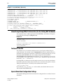
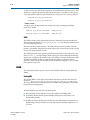
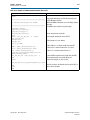
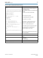
When you generate a custom MegaCore function, a Tcl script, named
<variation name>_constraints.tcl, is generated that contains the PPM clock group
settings in Example 4–1. These constraints are automatically written to your project
directory when you run the generated Tcl script. If you do not use the generated Tcl
script, you must specify the PPM clock group assignments manually. You can type the
assignments in Example 4–1 directly into the Tcl console window.
Example 4–1.
If (RX_NUM_LANES > 1 and Stratix II GX)
{
set_instance_assignment -name GXB_0PPM_CLOCK_GROUP_DRIVER 1 -to\
*rx_clkout_wire[0]
set_instance_assignment -name GXB_0PPM_CLOCK_GROUP 1 -to\ *xcvr2_inst|alt2gxb:\
|alt2gxb_component|channel_rec[*].receive
}
If (TX_NUM_LANES > 1 and Stratix II GX)
{
set_instance_assignment -name GXB_0PPM_CLOCK_GROUP_DRIVER 0 -to\
*tx_clkout_int_wire[0]
set_instance_assignment -name GXB_0PPM_CLOCK_GROUP 0 -to\
*xcvr2_inst|alt2gxb:alt2gxb_component|channel_tx[*].transmit
}
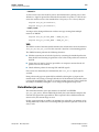
SerialLite II Deskew Support
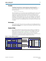
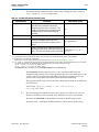
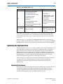
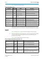
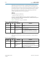
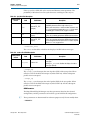
The Table 4–1 defines the parameters for the maximum receiver lane–to–lane deskew
tolerance for the SerialLite II MegaCore as specified at the FPGA pins. You can use
this information to ensure trace length differences do not exceed the timing budget.
The values include worst case lane–to–lane skew in the transceivers. To calculate in
terms of time units, multiply the value in Table 4–1 by the tx_coreclock clock period.
Table 4–1. SerialLite II Deskew Tolerance
SerialLite II MegaCore Function
User Guide
Transfer Size
Max Deskew (Cycles)
1
14
2
6
4
2
January 2014 Altera Corporation