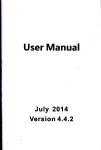
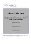
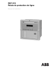
1
England
HY TEC ELECTRONICS LTD
USER MANUAL
FOR THE
HYTEC PCI/CAMAC
SERIAL HIGHWAY DRIVER
Type PCI 5992
PCI 5992
U PORT
DIN
D out
Issue 4:
March 2000
Author: H Wardell
PCI 5992/UTM/G/X/2.0
CONTENTS:–
Page
.
.
.
.
.
.
.
.
1.0
Product Summary
2.0
Setting up a System .
.
.
.
.
.
.
.
2.1 Byte or Bit Serial .
.
.
.
.
.
2.2 Clock Selection
.
.
.
.
.
.
2.3 Clock Speed .
.
.
.
.
.
.
2.4 Space Byte Insertion
.
.
.
.
.
2.4.1 Read/Write Functions .
.
.
2.4.2 Control Function Space Bytes
.
2.5 PCI passthrough Base Address
.
.
.
2.6 PCI Interrupt Line .
.
.
.
.
.
2.7 External Connections
.
.
.
.
.
2.7.1 Serial Highway Connections .
.
2.7.2 U–Port Connector
.
.
.
2.7.3 Message Started .
.
.
.
Using the PCI 5992 .
.
.
.
.
.
.
.
3.1 Insertion into the PC or workstation .
.
.
3.2 Initial State .
.
.
.
.
.
.
3.3 The Registers
.
.
.
.
.
.
3.3.1 Register 00 Condition Bits .
.
.
3.3.2 Register 04 12–Bit LAM Mask
.
.
3.3.3 Register 0C 12–Bit LAM Status
.
.
3.3.4 Interrupt Vector 08
.
.
.
.
3.3.5 U–Port Settings Register 48 .
.
.
3.3.6 Command Register (Register 14 Write) .
3.3.7 Transmit Data (Register 18 Write) .
.
3.3.8 Serial Status (Register 10 Read) .
.
3.3.9 Demand Status (Register 24 Read)
.
3.3.10 Read RXD Data
.
.
.
.
3.4 Test Facilities
.
.
.
.
.
.
3.4.1 LED Indicators .
.
.
.
.
3.4.2 Loop–Back Facility
.
.
.
.
3.4.3 Transmitted Command & Data Registers
3.4.4 Command FIFO .
.
.
.
.
3.4.5 Dump Store
.
.
.
.
.
PCI Bus Software Aspects .
.
.
.
.
.
.
Appendix and Figures 1 to 9
.
.
.
.
.
.
References
.
.
.
.
.
.
.
.
.
3.0
4.0
5.0
6.0
2
4
7
7
7
7
8
8
8
8
9
9
9
9
9
10
10
10
10
10
10
11
11
11
12
12
13
13
13
13
14
14
15
16
16
16
24
25
HYTEC Electronics Ltd
HEAD OFFICE: 5 CRADOCK Road, READING, Berkshire.
RG2 0JT ENGLAND. Tel: 0118 9757770 Fax: 0118 9757566
NORTHERN OFFICE: 64 AMY Street, LEICESTER, LE3 2FB.
ENGLAND. Tel: 0116 2630250 Fax: 0116 2630399
Printed in England. Issue 3. Mar–99
Incorporated in ENGLAND No. 1246940
Registered office: 5 Cradock road, Reading, Berkshire, ENGLAND. RG2 0JT
Our policy is one of continuous product development and the right is reserved to supply equipment which may vary slightly from that described.
3
1.0
Product Summary
Serial Highway Driver
Type PCI 5992
PCI
Features
Operates as a PCI Slave module.
Operates as an Interrupter.
Overall Interrupt Enable Bit.
Vector Writable and Readable.
Complies with CAMAC specification EUR6100E and I.E.E.E. 595.
Bit Serial and Byte Serial Modes at up to 5MHz.
Internal Crystal Controlled input with comprehensive dividing network.
Separate Reply Buffer.
64 Word FIFO Demand Buffer.
Lost Sync Indicator.
12 Bit Maskable LAM Register.
Repeat Read Mode.
Q–Scan Mode.
Reply Timeout.
Echo Mode.
Readout of transmitted message.
64 ’Byte’ Test Message Generator with facilities for forcing errors.
Module Booking mechanism for multi–master working.
Dump Store for message analysis.
Drive for Hytec U–Port Adaptor.
Readout of U–Port Setting & Main/Backup Loop States.
PCI 5992
U PORT
DIN
DOUT
Product Description
The Hytec PCI 5992 is a single short PCI module plus a passive plug
converter box which transmits and receives signals on the CAMAC
serial highway whilst being controlled via the PCI BUS. Bit serial and
Byte serial ports for data and clock are provided for the transmission
of command and the acceptance of reply and demand messages.
Serial messages are initiated by loading command and data
registers via the PCI bus using 32 bit words. Incoming messages are
checked for transverse and longitudinal parity. The serial clock is
controlled by a crystal source. The internal oscillator may be divided
down from the source to give transmission rates of approximately
1kHz to 5MHz.
A twelve–bit ”LAM” Status and ”LAM” mask register–set provide a
comprehensive interrupt system which has a separate overall allow
interrupt bit. The Lam status register may be cleared or selectively cleared
and the Lam mask register can be written, cleared, selectively set and
selectively cleared. The mask and all control registers are cleared at
power up, or by a PCIbus reset, or by a programmed reset.
4
Operational Features
Six registers provide communications between the PCI BUS and the Serial Highway. Message
transmission is initiated by:
1.
2.
Writing the command register with a serial Read or Command function or:–
Writing the Write Data register whilst the Command register contains a serial
Write function.
Loading the Command register with a serial Write Command does not initiate transmission. The 24
Bit Serial Read Data may be read via the PCI bus as one 32 Bit word after the reply message has
been received.
Receipt of a reply or otherwise together with the state of the serial SX and SQ may be determined
by reading the unit status register (offset – 00). The full status is obtained by reading offset 10. A
new transfer should not be set–up until a reply has been received for the previous transmission.
Two bits are provided in the command register so that a Q–scan mode may be utilised if the basic
parameters, function, crate are the same. The two bits are MQ and MR.
If MR is set, then a ’Read” to the module initiates a repeat message. The serial Command sent, is
identical if MQ=0, but is varied if MQ=1 depending on the state of the serial Q(SQ).
If SQ=1 then the serial address (SA) is incremented, whereas if SQ=0, SA is reset and the Serial
station number (SN) incremented.
If SN increments beyond 24, then the crate address is cleared and the new transmission made with
crate = 0. This gives address not recognised on receipt back at the PCI 5992 which interrupts
terminating the transfer.
Timeout
If 350mS elapses from the start of a message transmission and there has been no reply or
unrecognised command message, the TIMEOUT signal is asserted which sets TMO LAM source.
SHR also becomes true (SHR = RPL or TIMEOUT) and the RDY LAM source is set if/when CMD is
true. Reply messages received after TIMEOUT is asserted are ignored.
Addressing the Module
The module is addressed in passthrough mode as a PIC slave with base address set by plug and
play. The unit status register (00) contains a booking bit, which is automatically set following a read,
if previously unset.
The following table overleaf, gives the provisional register allocation for the ”passthrough offset
addresses”. The main ”passthrough address” is available as base address register 1 in the
configuration registers see section 4.0.
5
PCI 5992
REGISTER ALLOCATION
OFFSET
READ FUNCTION
WRITE FUNCTION
STATUS
2 BITS VALID
00
STATUS
04
LAM MASK
12 BITS VALID
08
VECTOR TOP UPPER
16 BITS VALID
0C
LAM STATUS
12 BITS VALID
10
SERIAL STATUS
12 BITS VALID
UNUSED
WRITE
READ 24 BIT DATA *
WRITE
1C
READ DUMPSTORE POINTER 10 BITS
WRITE DUMP STORE POINTER 10 BITS
20
READ DUMPSTORE AND INC. POINTER 8 BITS
ENABLE/DISABLE DUMPSTORE 1 BIT
24
READ DMD FIFD 12 BITS
28
READ CRATE ADD
(IF LOOP BACK) 6 BITS
2C
READ A
(IF LOOP BACK) 6 BITS
UNUSED
30
READ F
(IF LOOP BACK) 5 BITS
UNUSED
34
READ N
(IF LOOP BACK) 5 BITS
UNUSED
38
READ DATA
(IF LOOP BACK) 6 BITS
UNUSED
3C
READ DATA
(IF LOOP BACK) 6 BITS
UNUSED
40
READ DATA
(IF LOOP BACK) 6 BITS
UNUSED
44
READ DATA
(IF LOOP BACK) 6 BITS
48
READ UPORT
8 BITS
14
18
13 BITS VALID
LAM MASK
15 BITS
VECTOR WRITE
TOP 16 BITS ONLY
LAM STATUS
13 BITS
UNUSED
CNAF
22 BIT DATA
24 BIT DATA*
WRITE TEST FIFA
8 BITS
SET/CLR LOOPBACK
1 BIT
UNUSED
WRITE UPORT
3 BITS
4C
UNUSED
SPECIAL CLR, CLRS DMD, MR, TS.
50
UNUSED
& EVERYTHING (PROG, RST)
54
UNUSED
UNUSED
All registers are 32 bits wide with unused upperbits set at 0. An exception is offset 08 where
the vector top 16 bits is set. The bottom 12 bits is the LAM status with bits 12 – 15
indeterminate.
*Read data is as received from the serial highway.
*Write data is the message to be sent to the highway.
To read out going data use 28 – 44 in loopback mode.
6
PCI 5992 Expanded Register Detail
OFFSET
32 23 22 21 20 19 18 17 16 15 14 13 12 11 10 9 8
0
00
0<
16 BITS
>0
04
0<
16 BITS
>0
08
X<
16 BITS
>X –
0C
0<
0
0
SM SSM SCM CLR
–
>0 0 0
16 BITS
0
– –
0
7 6 5
4
INT
SE
ACB BYT DMD
LAM SHR XMR
EN
ERR
3
2
Q
X
1
0
RDY BKD
X X X X X X X X X X X X
–
– –
–
–
– –
–
–
– –
–
_ _
SE
AD– DE–
SCL ERR DMD XMR SHR TPE TMD LPE NR RR ERR SQ SX
DE–
M2 M1
RR SQ
10
0–0
0
14
0–0
0
18
0–X X X X X X X X X X X X X X X X X X X X X X X X
1C
0–0
0
0
0
0
0 0
20
0–0
0
0
0
0
0
24
0–0
0
0
0
0
0
0 0
28
0–0
0
0
0
0
0
0
0 0
0
0 0
0
2C
0–0
0
0
0
0
0
0
0 0
0
0 0
30
0–0
0
0
0
0
0
0
0 0
0
34
0–0
0
0
0
0
0
0
0 0
38
0–0
0
0
0
0
0
0
0 0
3C
0–0
0
0
0
0
0
0
0
0 0
0
0 0
40
0–0
0
0
0
0
0
0
0
0 0
0
44
0–0
0
0
0
0
0
0
0
0 0
48
0–0
0
0
0
0
0
0
0
4C
0–0
0
0
0
0
0
0
50
1–1
1
1
1
1
1
54
1–1
1
1
1
1
1
0
0
0
C32 C16 C8
0 0
C4
C2
0
C1
0
0 0
0 0
0 0
MQ MR N16 N8
0 0
0
0
0
0 0
0 0
C32 C16 C8
N4
N2
C4
N1 A8
C2
A4
C1
A2
A1 F16
F8
F4
SX ERR
F2
RST DMD
RST FIFO
PROG RST
CLR MR
LAM MASK
VECTOR
LAM STATUS
SERIAL STATUS
WRITE CNAF
R/W DATA
0 0 0
X X X X X X X X X X
R/W DMP PNTR
0
0
0 X X X X X X X X
READ DUMPST
0
0 0
SG– SG– SG– SG– SG–
M2
C32 C16 C8
L5 L4 L3 L2 L1
C2 C1
READ DMDS
0 0
0 X X X X X X X X
READ CRATE
0
0 0
0
X X X X X X X X
READ A
0 0
0
0 0
0 X X 1 X X X X X
READ F
0
0 0
0
0 0
0
X X 1 X X X X X
READ N
0
0 0
0
0 0
0 X X X X X X X X
RDTX1 DATA
0
0 0 X X X X X X X X
RDTX2 DATA
0 0
0
0 0 X X X X X X X X
RDTX3 DATA
0
0 0
0
0 0
X X X X X X X X
RDTX4 DATA
0 0
0
0 0
0
0 0
X X X X X X X X
READ UPORT
0
0 0
0
0 0
0
0 0
0 0
0 0
1
1
1 1
1
1
1
1
1
1
1 1
1
1
1
1
1
1
UNUSED
1
1
1 1
1
1
1
1
1
1
1 1
1
1
1
1
1
1
UNUSED
C4
0 X X X
*0 Is always 0
*X Is 0 or 1
*1 Is always 1
Offset – 4C
F1
STATUS
2
1
7
3
CLR Serial Interface DMD FIFO
CLRS Command FIFO
Reboot XYLINX
CLRS Repeat Bit
7
WRITE ONLY
2.0 Setting–up a System
2.1
Byte or Bit Serial
The selection of Bit or Byte Serial is dependant on the site circumstances. If the distances are
great, then the cable costs and the interbit skew can be excessive, and therefore Bit Serial
might be chosen. If distances are short, then normally Byte Serial would be chosen to increase
the system speed. Other factors may govern the choice such as the use of U–Port Adaptors
which may only operate in Bit Serial mode. Whatever the reason, the choice must be made,
and the links can be set as follows:–
For Bit Serial connect LK1 Pins 1 to 2.
For Byte Serial connect LK1 Pins 2 to 3.
Note:
All Serial Crate Controllers must also be set to the same mode.
For 4 byte waits before sync lost is reported, LK2 Pins 1 to 2.
For 8 byte waits before sync lost is reported, LK2 Pins 2 to 3.
2.2
Clock Selection
There is no choice of clock source on this module. The source is an Internal crystal clock
operating at 10 MHz.
2.3
Clock Speed
The clock speed and hence the system speed is largely determined by setting the amount by
which the selected clock is divided down. Selection is by links on SW2 and SW3, see
FIG 1.
Select
SW2
3
4
5
3
4
5
3
4
SW3
2
2
Frequency
–
5MHZ
2.5MHZ
1MHZ
500kHz
250kHz
100kHz
50kHz
25kHz
5
3
4
2
3
3
3
4
4
4
5
5
5
5
1kHz
8
10kHz
5kHz
2.5kHz
2.4 Space Byte Insertion
2.4.1 Read/Write Functions
Normal operation with standard serial crate controllers. LK4, 2 – 3.
In order to allow for the serial crate controller to reply, sufficient time must be allowed for it to
complete its in–crate or internal cycle. Hence the transmitted message is padded out with a
number of space bytes. For normal data messages, the minimum suggested number is in the
table that follows:–
Byte Rate
Mbytes/Sec
Write/Test
Function
Read
Function
< 0.5 *
8
4
0.5 – 1.5
9
4
1.5 – 2.0
10
6
2.0 – 2.5
10
6
2.5 – 3.0
11
7
3.0 – 3.5
11
7
3.5 – 4.0
12
8
4.0 – 4.5
13
9
4.5 – 5.0 **
14
10
* Note: All Bit Serial transfers are in this range.
** Note: Correct SCC operation is not guarenteed above 5Mhz.
This is based on the formula given in EUR6100(1982); S = N(OP) + N(REP) + 1 where N(OP)
and N(REP) are the number of received space bytes required to cover the maximum dataway
cycle time of the SCC and its reply. N(OP) is the next integer above T(OP) / T(byte) where T(OP)
the maximum data cycle time (assumed 1.2uS) and T(byte) is the minimum byte period of the
system. Note that larger numbers may be safely used at the expense of the system speed. The
relevant numbers are set in binary format on DIL Switch SW1, the maximum is 16, see FIG 1.
N.B. ”ON’ equals 0, therefore to set ’1’, the relevent switch is set ”off”.
NOTE:– The formula used, assumes that the crate controller replies immediately after the first
space byte. If it does not then the figures may be too low, hence if DERR and/or LPE status bits
are present. Increase the number of space bytes by 1 for a write and 2 for a read.
Space bytes when operating with ACB serial crate controllers. LK4, 1 – 2.
The CAMAC Serial Highway was specified assuming only one Serial Crate Controller per crate.
Allowance was made for other types of controller being present by making them give up the crate
if the Serial Crate Controller raised ACL on the ACB connector. This means that the serial Crate
controller is not held up for any long periods. The Serial Crate Controller was then given a space
to reply in, being defined by a number of space bytes. After the space bytes have finished, the
command is suspended and the Serial Highway Driver and the rest of the loop is able to accept
and send demands around the system, with any unfulfilled command being finally terminated
9
by the 350mS time–out delay.
If a Serial Crate Controller with an ACB connector is produced, then multiple controllers may be
present in a crate and each must use the Request/Grant system to gain access. This means that
any one controller may not be able to reply in the allowed space and hence the system will either
not work or must be slowed down considerably.
A way around this is to allow the space to expand until a reply is received from the addressed
controller. This is what has been done with the PCI 5992. If ACB mode is selected, space bytes
are generated until a reply is received.
There is of course a possible problem in that If no reply is received, then all demands are blocked
for the 350mS time–out period.
Things are not quite as bad as they may seem at first sight, because the problem only arises if
a SCC doesn’t reply having accepted the message. If no SCC accepts the message, then the
command will return around the loop and be received by the Serial Highway Driver. ”Address
not Recognised” will be raised, which will terminate the command and hence the space bytes.
The mode may also be used with single crate controllers to extend the range of each speed
selection and hence improve the throughput.
2.4.2 Control Function Space Bytes
Write control functions with N30 present act on the SCC itself, and may cause reconfiguration.
This can typically take 100mS. Provision is made to extend the number of space bytes to those
contained in 120mS if it is required to await a true reply, rather than accept the longer time–out
period. The decision is made by changing LK3 as follows. (See FIG 1.)
LK3
LK3
1 to 2
2 to 3
Delay IN
Delay OUT
2.5.0 PCI Passthrough Base Address
All working addresses are offsets of passthrough address 1. See section 4.
2.6
PCI Interrupt Line
The unit will interrupt on INTA only and should be set up to interrupt on mailbox 2. See section
4.
2.7 External Connections
2.7.1 Serial Highway Connections
The unit may operate with one of three configurations illustrated in FIG 2.
(a)
Two cable Byte mode:–
This may be considered the normal mode.
A 12 pair cable runs from the output ’D’ connector to the first SCC input ’D’ connector.
A 12 pair cable runs from the output ’D’ connector of the SCC, either to another SCC
input ’D’, or back to the input ’D’ connector of the SHD unit, ie, the final SCC output
returns to the SHD unit.
(b)
Two cable Bit mode:–
10
As above but the cable may be reduced to 2 pairs for economy.
(c)
Single cable with a minimum of four pairs:–
In this case a change–over plug is inserted in the output plug of both the last SCC
and the SHD unit, the remote clock and data return down the same cable.
2.7.2 U–Port Connector
The unit may be used to control and monitor a HYTEC UPA 0542 Master Fibre Optic U–Port
Adaptor, detailed data sheets are available by request. This is accomplished via a 15 way socket
labelled ’U–Port’. Note that U–Ports may be manually set and may still form part of the Serial
Highway system without being controlled from the SHD unit.
11
3.0 Using the PCI 5992
3.1
Insertion into the P.C. or Workstation
The unit should be plugged into any spare PCI slot.
3.2
Initial State
With the unit plugged in, cables attached to all units in the serial loop and all units powered, the
’SYNC’ LED on the front panel should be lit. Other LEDs should normally be ’OUT’. If the ’SYNC’
LED is not lit, then no clock is being received if in byte mode, or no ’wait’ bytes are being detected
if in serial mode.
Check:–
3.3
All cables are present.
All units are powered.
All units are set to the same mode.
The clock frequency is slow enough for the size of loop. It would be
advisable to start with a slow clock speed on new installations.
The Registers
The following assumes a working unit together with working modules in association. Fault finding
and test procedures are delt with later in this document. All offsets are from the base register
address 1. Loaded at bootup into offset 18 of the configeration register see section 4.0.
Control Registers offset 0016 – 1016 and register 4816 may be considered as control registers.
The most important of these is 0016, this contains various fixed bits plus a booking bit (bit 0)
useful for multiuser environments; the interrupt enable bit (bit 4), and copies of the most
important of the LAM Status bits. The unit may thus be operated on interrupts or by looping on
this address until the required condition arises.
3.3.1 Register 00 Condition Bits
Bit 0
Bit 1
Bit 2
Bit 3
Bit 4
=1
=1
=1
=1
=1
Bit 5 = 1
Bit 6 = 1
Bit 7 = 1
Bit 8 = 1
Bit 9 = 1
Bit 10= 1
Bit 11= 1
BUSY: Set after read if not set, cleared by Bit 0 = 1. (Booking bit).
RDY: Complementary to BUSY ie. available.
X response of last command.
Q response of last command.
INTEN: overall interrupt enable, set by writting Bit 4 = 1. Cleared when vector
written to mail box 2 following an interupt.
XMR: Command has transmitted, cleared by new command.
SHR: XMR present and reply received or time – out occured. Cleared by new
command.
LAM: one or more masked LAMs set, cleared when 04 bit is cleared, or OC
bit is cleared.
SERR: an error occured in the SYNC.
DMD: A demand message has been received. Cleared when OC bit is cleared.
Byte mode set. Cleared if bit mode set by link.
ACB mode set, cleared if normal mode set by link.
3.3.2 Register 04 12–Bit LAM Mask
This register determines which of the 12 LAM status bits is allowed to generate an interrupt,
assuming the overall enable bit is set.
Set and cleared by writing to 04.
Bit 12= 1
Clear all
12
Bit 13= 1 Selective clear mask bit as specified Bits 0 – 11
Bit 14 = 1 Selective set mask bit as specified Bits 0 – 11
3.3.3 Register 0C 12–Bit LAM Status
These bits are allowed to set interrupts if the corresponding bit in 04 is set.
Bit 0 = 1
Bit 1 = 1
Bit 2 = 1
Bit 3 = 1
Bit 4 = 1
Bit 5 = 1
Bit 6 = 1
Bit 7 = 1
Bit 8 = 1
Bit 9 = 1
Bit 10= 1
Bit 11= 1
Note:
SQ, the Q response to the last serial command was 0.
SX, the X response to the last serial command was 0.
ERR, an error was detected in the last command by an
addressed SCC. Usually /SQ and /SX will also be set as no
dataway cycle will have taken place.
DERR, indicates that an error was detected by the addressed
SCC in the previous message addressed to it.
ADNR, indicates that the crate address was not recognised
by any SCC on the Serial Highway. It is detected by the PCI 5992
detecting an output message with /M1 and /M2 both present
at its input socket.
LPE, indicates that a linear parity error was a detected in the
reply message.
TMO, indicates that no reply message was received in the
350mS since the last command message was sent.
TPE, indicates that a transverse parity error occurred on an
incoming message. Wait byte TPE are ignored.
SHR, indicates that a command sequence has completed, ie,
a good reply has been received, a time–out has occurred or
the command has returned as address not recognised.
XMR, indicates that the unit has finished transmitting the last
command.
DMD, indicates that a demand message has been received
since the status was last cleared.
SERR, indicates that the unit lost synchronisation for at least
four byte times.
All of the above bits are bit cleared or cleared by writing register 0C.
Bit 12 = 0 Clear all
Bit 12 = 1 Clear bit as specified in Bits 0 – 11.
3.3.4 Interrupt Vector Reg 08
The 32 bit vector used when interrupting is loaded by writing to the upper 16 Bits of register 0C.
It may be examined by reading register 08. The lower 16 bits will read as zero.
3.3.5 U–Port Settings Reg 48
Register 48 controls and monitors the state of a Hytec U–Port Adaptor if fitted. A write of register
48 lower four bits sets the available modes. A read of register 48 confirms the current settings
as written and also monitors the three lines which describe the actual connection state at the
adaptor, ie, MAIN LOOP Operable, BACK–UP Operable and internal or external clock. For full
information as to the use of these lines, please refer to the Hytec U–Port Adaptor manuals.
13
3.3.6 Command Register (Register 14 Write)
This 32 bit register is split into sections as follows:–
Bit 0 – 4
Function F1, F2, F4, F8 and F16 of the CAMAC Command to be used
in the remote crate.
Bit 5 – 8 Subaddress A1, A2 ,A4 and A8 of the CAMAC Command to be used in
the remote crate.
Bit 9 – 13 Station number N1, N2, N4, N8 and N16 of the CAMAC Command to be
used in the remote crate.
Bit 14
MR, this is a special bit which when set causes an automatic repeat of
the current read command (if any) immediately following a read of the
lower byte of register 1A. A block read is thus possible on the same
location.
Bit 15
MQ, this is a special bit which when set in conjunction with MR, causes
an automatic repeat read with the Subaddress advanced by one if the
received Q=1. If Q=0, then the Subaddress is cleared to zero and the
station number advanced by 1 before doing a repeat read. This forms
the Q–Scan of the crate. When the station has incremented to 24, then
the crate address is made zero which returns as ADNR and terminates
the transfers.
Bit 16 – 25 Crate address.
Note: 1
If MR and MQ are both zero then only a single transfer takes place.
Note: 2
If the Function specified is a read then the message is transmitted on receipt
register 14, ie, when the Function is loaded. If the Function
is a write, then the message is transmitted when the data has
been loaded.
Note: 3
This register forms part of the message sequence so
that the data can not be read back under normal operation.
3.3.7 Transmit Data (Register 18 Write)
Bits 0 – 23 of register 18 form bits 1 – 24 of the CAMAC data to be sent to the remote crate. If
a write command is present in register 14 then transmission commences on receipt of this data.
Note, a block transfer to the same CAMAC location therefore only requires the data to be loaded.
The command information may be re–used.
Serial Highway Status:
Registers 10 and 24 are status registers containing information
read from the Serial Highway. They must be used in conjunction with the LAM Status Register
(0C) and/or the Device Status Register (00) in order to confirm whether they are valid.
3.3.8 Serial Status Register (Register 10 Read)
This register contains the status information which was received in the last reply message from
the last addressed SCC. It is only valid after the setting of RDY in the LAM Status Register (OC),
but remains true until a new command is issued. It is necessary therefore, to ensure that RDY
is cleared prior to issuing a new command or initiating one if in repeat mode.
Bits 6 – 11 Crate address of replying SCC.
Bit 0 = 1 ERR, an error was detected in the command message just terminated.
Bit 1
SX, X response to the command just terminated, always 0 if ERR set or
M1 = M2 = 0.
14
Bit 2
Bit 3
Bit 4 & 5
SQ, Q response to the command just terminated, always 0 if ERR set or
M1 = M2 = 0.
DERR, SCC had an error in the previous command addressed to it.
M1 and M2 copy of the command/reply definition bits received in the
second byte of the serial reply message.
3.3.9 Demand Status (Register 24 Read)
This register (24) contains the demand information received from the Serial Highway via an
unsolicited demand originating in one of the possible 64 crates. It is not a true register, but is the
current output from a 64 word FIFO memory. Because of this, the data may only be read once
and is only valid if DMD is set in the LAM Status or Unit Status. It must not be read on the fly,
but only in answer to a DMD being set. This DMD should be cleared before reading the DMD
status. Reading the DMD status clears the current information and will reset DMD if a further
DMD is outstanding.
Bits 0 – 5 Crate address of the originating SCC.
Bits 6 – 10 Graded LAM describing the source of the interrupting device.
Bit 11
M2 as received, should be 1 for a true DMD message.
3.3.10 Received Data
Register 18 read contains the data received from the addressed crate for the last transmitted
Serial Highway command. The data is only valid if the last command has terminated and a reply
has been received, ie, RDY has been set. The data remains valid until a new command starts
to transmit. It is therefore essential that the RDY status is cleared before issuing a new command
or reading the registers if MR is set, as the reading of the data register triggers the new command.
3.4
Test Facilities
The following facilities have been added to aid testing and fault finding:–
a)
A loop–back facility to by-pass the external Serial Highway.
b)
Read back of command and data 6–bit bytes with the corresponding parity and delimiter
bit, ie, 8–bits.
c)
A 64 byte command generator FIFO store.
d)
A 1kbyte DUMP store which can be set to monitor the incoming 6–bit data patterns
received by the unit.
3.4.1 LED Indicators
Four LED indicators have been provided to enable the operator to visually observe the operation
of the unit, they are as follows:–
a)
The PWRD LED indicates that the unit is powered.
b)
SYNC monitors the state of synchronisation of the unit. If present, it indicates that the unit
is receiving clock pulse if in Byte–Mode or detecting ’wait’ bytes or synchronised data if
in Bit–Mode.
c)
MSG indicates that a serial command has commenced transmission. It is present for
approximately 100mS following the first byte of the command sequence.
15
d)
ADD indicates that the unit is being addressed from the PCI bus. Each access results in
the LED being illuminated for approximately 100mS.
3.4.2 Loop–Back Facility
NB: UNIT SHOULD BE SET TO BYTE MODE. With so many units possibly connected on a
Serial Highway, it is necessary to confirm that the fault, if any, is within the PCI 5992 or external
to it. A facility to externally exclude the Serial Highway and the drivers and receivers of the PCI
5992 has been provided. The loop–back (LB) is made by connecting the internal source of
signals to the received signals path without going via any cables at the same time ”Wait Bytes”
are continuousley transmitted on the main loop. The facility is activated by writing bit 0 = 1 in
register 28 and cleared by writing bit 0 = 0. In this mode any command will be returned as if the
external crate did not recognise the crate address, ie, ADNR will be set. The facility becomes
extremely powerful when used with the following facilities.
3.4.3 Transmitted Command and Data Registers
The command data and write data when loaded is split up into the sequencing registers in the
6–bit bytes to be transmitted. These are only allowed on to the internal bus at the correct time
as the bus is normally transmitting wait byte in the quiescent state. Any switching whilst in the
normal operating mode would therefore create errors all around the serial loop. The facility to
read back this data in the form in which it would be transmitted is therefore limited to the LB state.
With the unit set to Loop–Back (LB) then the 8–bit pattern which would be transmitted may be
selected as follows:–
16
Register 28
Bit 0 – 6
Bit 7
Bit 8
Register 2C
Bit 0 – 4
Bit 5 = 1
Bit 7
Bit 8
Register 30
Bit 0–3
Bit 4 = 0
Bit 5 = 0
Bit 7
Bit 8
Register 34
Bit 0 – 4
Bit 5 = 1
Bit 6
Register 38
Bit 0 – 5
Bit 6
Bit 7
Register 3C
Rd Tx Crate Address
Crate Address.
Delimiter bit should be 0.
Transverse parity bit making odd parity.
Rd Tx N
N – Station number in the remote crate.
Always 1.
Delimiter bit should be 0.
Transverse parity.
Rd Tx A
A – Subaddress in the remote crate.
Message identifier M1 = 0 for command.
Message identifier M2 = 0 for command.
Delimiter bit should be 0.
Transverse parity.
Rd Tx F
F – Function to be used in the remote crate.
Always 1.
Delimiter bit should be 0.
Rd Tx Data 19 – 24
Tx Data bits 19–24 for the remote crate.
Delimiter bit should be 0.
Transverse parity bit.
Rd Tx Data 13 – 18
Bit 0 –5
Bit 6
Bit 7
Tx Data bits 13 – 18.
Delimiter bit should be 0.
Transverse parity bit.
Register 40
Bit 0 – 5
Bit 6
Bit 7
Rd Tx Data 7 – 12
Tx Data bits 7 – 12.
Delimiter bit should be 0.
Transverse parity bit.
Register 44
Rd Tx Data 1 – 6
Bit 0 – 5
Bit 6
Bit 7
Tx Data bits 1 – 6.
Delimiter bit should be 0.
Transverse parity bit.
17
3.4.4 Command FIFO
A 64–byte 8–bit Command FIFO is available for generating test message which may be set up containing
errors if required. The FIFO is arranged to substitute for the message command and data registers, and
because it changes over without discontinuities, it can be used either on LB or with the serial interface
complete. Messages not normally issued by the Serial Highway driver can thus be sent around the loop;
ie, commands, demands, truncated commands, replies, wait bytes with parity errors or incomplete
messages. The FIFO is set up as follows:–
Register 24 write. Starting with a ”wait” byte load each 8–bit Serial Highway byte of the required message
until complete. See formats in FIGs 4 – 9 in the appendix. The final byte for a command message must
be correct longitudinal parity followed by as many space bytes as required plus at least two wait bytes (one
is the end byte). For other messages at least one wait byte should be located following the delimiter byte.
When complete, the FIFO contents are transmitted by writing zero or any other read to register 14. No crate
address is required as the information is not used. The FIFO will then take over and release when
transmission is complete. Note that only one command message should be loaded if correct operation is
required.
3.4.5 Dump Store
Another facility is a 1kbyte Dump Store which may be set up to receive up to 1k worth of the 8–bit bytes
received from the Serial Highway for analysis. The store only collects non–wait bytes except for the wait
byte immediately following a message sequence. It is set up by writing the address pointer to zero. Write
register 1C = 0, and then the store is started by Enable Dump Store Register 20 bit 0 = 1. Collection is
stopped by writing register 1E bit 0 = 0. The pointer should then be read by register 1C read, and the
number stored. This represents the valid number of entries for the sequence. The pointer should then be
reset, register 1C = 0, and the store read and the pointer incremented by register 20 read for valid number
of entries. The Dump Store may be used at any time.
18
4.0 PCI Addressing
The unit makes use of a specialised PCI compliant ASIC, to communicate with the PCI Bus.
All ”PCI”commands are dealt with by the device within the eight clock pulse time–out period for reading
and writing of the configuration and operational registers.
Two sets of base addresses are loaded by plug and play at boot – time following requests lodged via the
configuration PROM.
Base address 0 gives the base address for the configuration and operational registers.
Base address 1 gives the base addresses for the passthrough region and thus the offsets for the module
control registers.
4.1 Configuration Registers
This consists of a 256 byte configuration Reader space, some of which is mandatory for the compliant
device. Part of this space is read only and is sourced by a PROM to enable the ”plug and play” facility. The
PROM may be extended as an expansion ROM, not currently used.
Configuration Registers:– These are read by the M/C bios system on power up and are registered by the
Address Offset
00H
04H
08H
0CH
10H
14H
18H
1CH
20H
24H
28H
2CH
30H
34H
38H
3CH
Register Name
Outgoing Mail Box 1
Outgoing Mail Box 2
Outgoing Mail Box 3
Outgoing Mail Box 4
Incoming Mail Box 1
Incoming Mail Box 2
Incoming Mail Box 3
Incoming Mail Box 4
FIFO Register Port (Bi–directional)
Master Write Address
Master Write Transfer Count Register
Master Read Address Register
Master Read Transfer Count Register
Mail Box Empty/Full Status
Interrupt Control/Status Register
Bus Master Control–Status Register
operating system.
19
Comments
Unused
Unused
Unused
Unused
Unused
Interrupt Register
Unused
Unused
Unused
Unused
Unused
Unused
Unused
MB2 Only
Set to MB2
Unused
4.2 Operational Registers
The operational registers are again registers contained within the PCI Bus ASIC.
They consist of 16 Registers (D words) located at the address space specified by the Base Address Register 0.
Configuration
Address Offset
00H – 01H
02H – 03H
04H – 05H
06H – 07H
08H
09H – 0BH
0CH
0DH
0EA
0FH
10H – 27H
28H – 2FH
30H
34H – 3BH
3CH
3DH
3EH
3FH
40H – FFH
Register Name
Hytec Identification (1196H)
Device Identification (5992)
PCI Command Register
PCI Status Register
Revision Identification Register
Class Code Register
Cache Line Size Register
Master Latency Timer
Header Type
Built–in Self Test
Base Address Registers (0–5)
Reserved
Expansion ROM Base Address
Reserved
Interrupt line
Interrupt Pin
Minimum Grant
Maximum Latency
Not used
Comments
PCI Registered No.
PCP’s Ident
Unclassified
N/A
N/A
N/A
O & I Used
Not Currently Used
N/A
N/A
4.3 Expansion ROM
The contents of this ROM which is an extension of the configuration ROM is to be determined.
It is addressed as from the Expansion ROM Base Address Register and including the 256 bytes configuration area is a maximum of 64K bytes
4.4 Drivers
Suitable drivers will be avaliable for:–
Windows 98
Windows NT
V.M.S.
4.5 Support Software
Support software is under review and will be specified at a later date.
.
20
5.0 Appendix
Frequency Selection
2
SW2
2
SW3
LK2
3
1
4
5
3
1
5
1
2
4
SYNC. LOST
DELAY
3
XILINX
ACB/NORMAL
40IDE
CONTROL FUNCTION
DELAY.
3 2 1
LK4
LK3
3
2
1
68
WAY
SPROM
AMCC
’MATCH MAKER’
1 2 3
LKI
BIT / BYTE
Selection
FIG. 1
21
ON
R8
4
2
R1
W8
4
2
W1
OFF
E PROM
SPACE BYTES
ON = 0
OFF = 1
D
O
U
T
CLK OUT
SCC(1)
SCC(2)
D
D
CLK
I
N
DATA 8–Bits
D
D
I
N
CLK IN
I
N
D
DATA 8–Bits
O
U
T
O
U
T
DATA 8–Bits
VSD 2992
BYTE SERIAL
D
O
U
T
CLK OUT
SCC(1)
SCC(2)
D
D
CLK
I
N
DATA 1–Bit
D
D
I
N
CLK IN
DATA 1–Bit
I
N
D
O
U
T
O
U
T
DATA 1–Bit
VSD 2992
BIT SERIAL
CLK IN
D
O
U
T
D
I
N
CLK OUT
DATA OUT
DATA IN
SHORTING
PLUG
SCC(1)
SCC(2)
D
D
I
N
I
N
D
D
O
U
T
O
U
T
VSD 2992
SINGLE ENDED BIT SERIAL
FIG 2.
22
SHORTING
PLUG
PCI 5992 Serial Highway Connectors
Output Socket (type DB–25S)
Input Plug (type DB–25P)
D–IN
1
2
3
4
5
6
7
8
9
10
11
12
13
14
15
16
17
18
19
20
21
22
23
24
25
GND
GND
Bit Serial
Data I/P
Bit Serial
Data O/P
Byte Serial
Data I/P
Byte Serial
Data O/P
Clock O/P
Clock I/P
NU
NU
Fig 3.
PCI 5992 U–Port Connector
Socket Type 1.5:1 D Connector
1
2
3
4
5
6
7
8
9
10
11
12
13
14
15
EXTCLK
GND
BS3
MAIN
GND
BS2
BACK
GND
BS1
Fig 4.
23
1
2
3
4
5
6
7
8
9
10
11
12
13
14
15
16
17
18
19
20
21
22
23
24
25
D–OUT
MSB
8
7
6
b
0
SC32
b
0
0
0
b
0
1
b
0
1
b
0
SW24
SW19
BYTE 5 *
b
0
SW18
SW13
BYTE 6 *
BYTE 7 *
BYTE 8 *
5
4
3
2
LSB
1
SC1
HEADER BYTE
SA1
BYTE 2
SF16
SF1
BYTE 3
SN16
SN1
BYTE 4
SA8
b
0
SW12
SW7
b
0
SW6
SW1
b
0
c
c
c
1
0
1
1
1
c
1
c
c
1
1
b = Odd Byte – Parity Bits.
c = Even Column – Parity Bits.
* Bytes 5,6,7,8 included if SF16 = 1 and SF8 = 0.
SUM BYTE
SPACE BYTES
AS REQUIRED
1
0
1
1
1
1
1
1
1
1
1
0
0
0
0
0
Fig 5.
MSB
8
7
6
0
5
4
3
2
M
0
*
FUNCTION
0
*
STATION NUMBER
I
Command Message: Bit Assignments
LSB
1
CRATE ADDRESS
0
END BYTE
HEADER BYTE
SUB–ADDRESS
0
WRITE DATA
0
WRITE DATA
0
WRITE DATA
0
WRITE DATA
0
COLUMN PARITY
0
SPACE
COMMAND
SPACE
1
END
7
6
b
0
SC32
1
1
1
5
4
3
2
LSB
1
SC1
0
0
0
0
0
END BYTE
Truncated Command Message:
Bit Assignments
WRITE DATA
(if required)
MSB
8
SUM BYTE
7
6
5
4
3
2
0
CRATE ADDRESS
1
END
LSB
1
DELIMITER BITS
BYTE PARITY BITS
Truncated Command Message:
Field Assignments
END BYTE
DELIMITER BITS
BYTE PARITY BITS
* Reserved Bits.
MI = Message Identifier Field.
HEADER BYTE
b = Odd Byte Parity Bit
SPACE BYTES
AS REQUIRED
0
MSB
8
Fig 6.
Command Message: Field Assignments
24
HEADER BYTE
END BYTE
MSB
8
7
6
b
0
SC32
b
0
1
b
1
c
5
4
3
2
SGL5
c
c
c
c
LSB
1
SC1
HEADER BYTE
SGL1
BYTE 2
c
ENDSUM BYTE
b = Odd Byte Parity Bits.
c = Even Column Parity Bits.
Demand Message: Bit Assignments
MSB
8
7
6
0
0
1
5
4
3
2
LSB
1
CRATE ADDRESS
MI
SERIAL GRADED L
COLUMN – PARITY
DELIMITER BITS
BYTE PARITY BITS
HEADER BYTE
SGL BYTE
ENDSUM BYTE
MI = Message Identification Field.
Demand Message: Field Assignments
Fig 7.
25
Table: Length of Command/Reply Transactions
Number of Bytes
Function Field
Operation
Read
Control
Write
F16
F8
0
0
0
1
1
1
1
Command from
Header to
SUM
Inclusive
Reply from
Header to
ENDSUM
Inclusive
Command/
Reply
Transaction
5
7
12*
5
3
8*
9
3
12*
0
* Minimum length, assuming that Reply Header is transmitted by SCC as first SPACE byte
is received, and ENDSUM is transmitted as END byte is received.
Table: Contents of Message Identification Field
MI–Field
Message
M2
M1
Command
0
0
Reply
0
1
Demand
1
–
FIG 8.
26
MSB
8
7
6
b
0
SC32
b
0
0
b
0
SR24
SR19
BYTE 3 *
b
0
SR18
SR13
BYTE 4 *
b
0
SR12
SR7
BYTE 5 *
b
0
SR6
SR1
BYTE 6 *
b
1
c
5
4
3
2
LSB
1
SC1
1
c
DERR SQ
c
c
SX ERR
c
c
HEADER BYTE
BYTE 2
b = Odd Byte – Parity Bits.
c = Even Column – Parity Bits.
* Bytes 5,6,7,8 included if SF16 = 1 and SF8 = 0.
ENDSUM Byte
Reply Message: Bit Assignments
MSB
8
7
6
0
0
M
5
4
3
2
LSB
1
CRATE ADDRESS
HEADER BYTE
I
STATUS BYTE
STATUS
0
READ DATA
0
READ DATA
0
READ DATA
0
READ DATA
0
COLUMN PARITY
MI = Message Identifier Field.
READ DATA
(if required)
ENDSUM BYTE
DELIMITER BITS
BYTE PARITY BITS
Reply Message: Field Assignments
Fig 9.
27
6.0 References
EUR4100
CAMAC Specification 1969ON.
EUR6100
Serial Highway and Serial Crate Controller Type L–2.
HYTEC
Serial Crate Controller SCC 2401.
HYTEC
Master Dual Fibre–Optic U–Port Adaptor UPA542.
HYTEC
Slave Dual Fibre–Optic U–Port Adaptor UP541.
HYTEC
Serial Highway Driver SHD 992 (CAMAC : CAMAC).
HYTEC
Serial Highway Driver VSD 2992 (VME; CAMAC).
IEEE 595
28