1
TS800
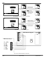
Main PCB Layout
LEC8
Digicom DC28
(under)
DC 28
Novram
To B.T. Line
PL 2
Main Board
6 Ah Battery
NOTE: not fitted
on the TS800R
Loud
Speaker
(under)
Mains
Terminals
Fig 1 TS800 Panel Layout
Output Module
JP5
JP4
Outputs for Bell, Strobe,
Fire Reset, Aux Output
and Aux Tamper input.
Terminals for Digicom
DC28 connector
MIN
MAX
Sounder Volume adjust
Vol
LCD
LK 1
Terminals for
Circuits 1-8
LK 2
Jp1
Remote Keypad
Connections
Tamper
switch
Remote
Novram
Local Expansion
Card (LEC8)
LINKS
LK.1: Factory Default
LK.2: Digicom Reset/Test
LK.3: TH Link
LK.4: Walk Test polarity
FUSES
F1: 2A Sounder supply
F2: 160mA Mains input
F3: 1A QB Aux supply
F4: 1A QB Bell Supply
LK3
Printer CPA6 or RS 232 via
Menvier Security Printer adapter
JP2
F1: 2A
F3: 1A
F4: 1A
Keypad
LK4
NEUTRAL
LIVE
EARTH
Outputs for Walk Test,
Extension
Loudspeakers
and Aux 12V
Mains Input
F2: 160mA
Battery
Earth
To Front cover
Fig 2 Main PCB Layout
496528 Issue A
3 of 10
TS800