1
TS800
TS800 MAIN PCB
Detector Sw
Detector Sw
Z1
Normally
open
contact
Circuit 1
Tamper Sw
T1
Tamper Sw
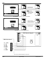
Fig 4 DP Wired Circuit Connections
Installing a Local Expansion Card (LEC8)
Installing Remote Keypads (TS800.REM)
If more than eight zones are required then a LEC8 is
fitted inside the TS800 case as follows:
At least one Remote Keypad is required for a TS800R
and up to four may be fitted at suitable locations with
cables connected to the main PCB ‘REMOTE’ terminals
using 6 core cable (Fig 7):
(1)
Fit the four posts supplied to the LEC8 PCB
then position the LEC in the base and secure it
by pushing the posts into the holes provided
(Fig 1);
(2)
Fit the connector supplied by connecting it
between JPI on the LEC8 and JPl on the
Control Panel main PCB (Fig 2);
(3)
Connect the detection circuit cables to the
LEC8 (Fig 3 and 4).
(1)
In a Daisy Chain configuration in which case the
cable length to the last Remote Keypad must
not exceed 100m to prevent excessive voltage
drop in the cables (Fig 5);
(2)
In a star configuration in which case the cable
between the Remote Keypad and Panel must
not exceed 100m to prevent excessive voltage
drop in the cables (Fig 6);
The PCB is secured to the cover by a screw. The base
and cover clip together.
496528 Issue A
(1)
Open the Remote Keypad case by using a
screwdriver to depress two of the retaining clips
inwards from their cover indents to release the
top or bottom then remove the cover complete
with its PCB;
(2)
Secure the Remote Keypad base in its required
location using the keyhole and two fixing holes
then feed the cable/s through the cable entry,
prepare the ends and connect them to the
terminal block on the Remote Keypad PCB.
(3)
When all the required Remote Keypads are
fitted and cables connected make the
connections at the main PCB.
5 of 10
TS800