1
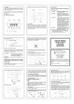
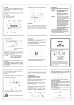
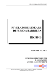
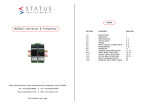
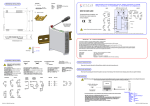
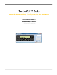
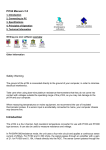
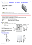
INDEX
DM3600U
Single Channel Universal Input 6 Digit Indicator
Status Instruments Ltd, Green Lane Business Park, Tewkesbury, Glos. GL20 8DE
Tel: +44 (0)1684 296818
Email: [email protected]
52-314-2367-01
Fax: +44 (0)1684 293746
Web: www.status.co.uk
Issue: Web
SECTION
CONTENTS
PAGE NO.
1.0
2.0
3.0
4.0
5.0
6.0
7.0
8.0
9.0
10.0
11.0
12.0
13.0
14.0
15.0
DESCRIPTION
UNPACKING
INSTALLATION
OPTION PODS
CONFIGURATION OPTIONS
MECHANICAL
SPECIFICATION
INSTRUMENT CONFIGURATION
MENU MODE
MENU MAP
RESETTING THE DEVICE
INPUT MENU STRUCTURE
OUTPUT MENU STRUCTURE
SYSTEM MENU STRUCTURE
FAULT FINDING
1
1
2-3
4-5
5
6-7
7-10
10-11
11-12
13
13
14-17
18-20
21-22
23
1.0 DESCRIPTION
3.0 INSTALLATION
The DM3600 is a highly accurate and stable digital process indicator that accepts all commonly used process
signals. The unit can be used "stand alone" or with the Modbus serial communications option, as part of a
larger system. The case design enables Option Pods to be easily installed without the need for dismantling
or re-calibration. A range of Pods are available for:
Relay outputs
Isolated (4 to 20) mA re-transmission
FRONT PANEL
SEALED
TO IP66
BRIGHT SIX
DIGIT
DISPLAY
DISCRETE LED
ALARM
INDICATORS
CYCLE
KEY
SHIFT
KEY
INCREMENT
KEY
WARNING !
INSTALLER - This section must be used by competent personnel only. If this equipment is not installed
in accordance with these instructions, protection against electrical hazards may be impaired. It is the
responsibility of the person installing this equipment to implement this procedure in accordance with the
relevant code of practice (for the installation of instrumentation used in process control systems), issued
by a recognised local body.
MOUNTING - This equipment is classed as PERMANENTLY CONNECTED EQUIPMENT. Hazardous voltages
may be present on the terminals of this equipment. The equipment must be panel mounted into a suitable
enclosure which provides at least IP20 protection behind the panel.
SUPPLY - The supply terminals and associated internal circuitry are isolated from all other parts of the
equipment in accordance with BS EN61010-1, for connection to an installation over-voltage Category II
supply, (pollution degree 2). The supply voltage and frequency must remain within the limits stated on the
product label. The mains supply to the unit must be protected by an external 1 A fuse and a suitable switch
or circuit breaker must be located close to the equipment, in order to isolate the supply.
SIGNAL INPUT/OUTPUTS - All signal input, and communication terminals and associated internal circuitry
are intended for operation at voltages less than 40 VDC. These circuits, which may become accessible
during NORMAL OPERATION, must ONLY be connected to signals complying with the requirements for Safety
Extra Low Voltage (SELV) circuits.
1A 1B 2A 2B
°C
(Read the following safety information before installation)
Tag No.
RELAYS - The relay terminals and associated internal circuitry are isolated from all other parts of the
equipment in accordance with BS EN 61010-1, for connection to an installation over-voltage Category II supply,
(pollution degree 2). The relay operating voltage and current must remain within the limits stated. (Refer
to Section 7.0).
LEGEND
WINDOW
SERVICE - This equipment contains no user serviceable parts and must be returned to supplier for repair.
OPTION
POD SLOT 1
OPTION POD
SLOT 2
(NOT SHOWN)
3.1 INSTALLING INTO A PANEL
The maximum panel thickness is 10 mm. The instrument case has an integral gasket which forms a seal
when the instrument is tightened against the panel. The panel should be clean, smooth and at least 1.6 mm
thick for the seal to be effective.
PROCESS
INPUTS
RJ45 COMMS
+ DIGITALS
POWER
CONNECTOR
The diagram below shows the rear panel positions for all electrical connections.
2.0 UNPACKING
WARNING
Use only the retaining screws provided to clamp the instrument to the panel (screws
must be tightened sufficiently to effect a seal but must never be over tightened).
3.2 WIRING
Please inspect the instrument carefully for any signs of shipping damage. The packaging has been designed
to provide maximum protection, however, we cannot guarantee that mishandling will not have damaged
the instrument. In the case of this unlikely event, please contact your supplier immediately and retain the
packaging for subsequent inspection.
Page 1
All connections are made to sockets which are removable for ease of maintenance.
NOTE: CABLE SIZE (0.5 to 1.5) mm²
Page 2
3.3 POWER SUPPLY
4.0 OPTION PODS
The Power supply rating will be indicated on the top of the instrument, ENSURE IT IS CORRECT FOR THE
APPLICATION.
THE MAINS SUPPLY TO THE EQUIPMENT MUST BE PROTECTED BY AN EXTERNAL 1 A FUSE AND A
SUITABLE SWITCH OR CIRCUIT BREAKER WHICH SHOULD BE NEAR THE EQUIPMENT.
NOTE: USE 600 VRMS CABLE (0.5 TO 1.5) mm².
4.1 INSTALLING PODS
Power must be removed from unit before adding/removing a pod. Slot 1 (alarm 1A and 1B) should be
positioned on the left side of the unit looking from the front to correspond to front panel alarm indicator,
Slot 2 (alarm 2A and 2B) is positioned on the right.
To install an Option Pod, slide back the cover to its next engaging position and push the pod connection
within the mating connector. To remove an Option Pod, disengage the supporting latch situated beneath
the pod by pushing the back cover forward, the pod can then be lifted away from the instrument connector.
4.2 DUAL RELAY POD. POD-3000/02000000
(+) L
The relay pod has two "change over"relays with a common wiper.
N (-)
3
4
NC
2
NO
1
NC
NO
3.4 SENSOR CONNECTIONS
WIPER
Wires are retained by screws. Ensure that the exposed section of the wire is fully inserted and that no
loose strands are exposed.
5
All sensor connections are made via the five way "fast wiring" socket at the rear of the unit (wire size
(0.5 to 1.5) mm²).
NOTE: THERMOCOUPLE, RTD AND VOLTAGE INPUT A SCREENED CABLE IS RECOMMENDED FOR RUNS
GREATER THAN 10 m.
1
2
NOTE: USE 600 VRMS CABLE (0.5 TO 1.5) mm²
NOTE: ANY CIRCUIT WITH AN AC POTENTIAL GREATER THAN 33 VRMS AND 46.7 V PEAK MUST BE
PROTECTED WITH A 5 A(T) FUSE WHEN CONNECTED TO THIS POD.
To make a connection: Insert small screwdriver blade into tension clamp orifice (1), push and twist to
deflect clamp into open position. Do not lever screwdriver thus forcing connector body sideways. Insert
conductor tail sufficiently into (2) then release screwdriver. Ensure no loose wire strands protrude.
Page 3
Page 4
4.3 ISOLATED (4 TO 20) mA RE-TRANSMISSION POD. POD-3000/03
6.0 MECHANICAL DETAILS
The re-transmission pod (when fitted) is designed to provide (0 to 10) mA, (0 to 20) mA or (4 to 20) mA output
in active or passive modes. The output can be any portion of the display. The pod can be used in two
modes:
Active (Source)
Passive (Sink)
-
R Load
V
+
2
3
4
1
5
2
ABS/PC
IEC707 FV0, UL 94VO
230 g
(92 x 45) mm
All dimensions are in mm
R Load
Max RLoad = 1 K
1
Material
Flammability
Weight
Panel cut out
3
4
RLoad < (V-2) KΩ
22
And Vmax = 30 V
5
96.0
5.0 CONFIGURATION OPTIONS
48.0
1A 1B 2A 2B
Configuration can be performed in two ways. The first configuration method is to use the menu structure
interface, standard on every DM3600 unit. The second configuration method is to use the optional factory
fitted MODBUS RS485 communications option. To enable easy configuration via comms, the user can
download M-Config from www.status.co.uk. This is a free Windows application to allow the user to easily
and intuitively configure DM3600 devices. For more information regarding the DM3600 MODBUS implementation,
please contact your supplier.
VAC
11.0
Tag No.
131.0 BEHIND BEZEL
5.1 COMMUNICATION/DIGITAL INPUT OPTION
When fitted this option provides the user with either 4 or 2 wire RS485 serial communications together two
digital inputs. Connections are made via a RJ45 connector. A 0.5 m interface is supplied with this.
DISCRETE INPUT CONNECTION
DIS 1
+
To activate, apply voltage (5 to 24) V
DIS 2
(5 to 24) V
-
Max Current =
Per Channel
DIS Com
V
1600
A
Reverse connection and over voltage protected.
140.0
+RX
-TX
+TX
-RX
DIS2
COMS COM
DIS1
DIS COM
IP65 SEAL TO PANEL
10 mm MAXIMUM PANEL THICKNESS
OPTION POD
RJ45
CLAMPING SCREW
PANEL CLAMP
Page 5
Page 6
All dimensions in mm
6.2 OPTION POD
19.5
THERMOCOUPLE
13.5
53.5
16.0
43.5
7.0 SPECIFICATIONS @ 20°C
UNIVERSAL INPUT TYPES
SENSOR
mA
RTD
T/C
mV
Volts
RANGE AND LINEARISATION
4 to 20, ± 20, ± 10
Pt100, Ni120, Custom*¹
K, J, T, R, S, E, L, N, B, Custom*¹
± 100 mVDC
± 10 V, ± 5 V, (1 to 5) V, ± 1 VDC
Minimum Span
Any span within the range can be selected, but the recommended span is
> 10 % of range
CURRENT INPUT
Basic Accuracy
Thermal Drift
Input Impedance
0.05 % FS ± 0.05 % of reading*²
0.02 %/°C
20 Ω
3/2
5/2
Linear, X½, X , X , Custom*¹
Linearity
A 19.5 V ± 0.5 V @ 25 mA isolated power supply is available to power the current loop. (Short circuit
protected)
RTD
Sensor Range
Linearisation
Basic Accuracy
Thermal Drift
Zero
Span
Excitation Current
Lead Resistance Effect
Max Lead Resistance
(-200 to 850) °C (18 to 390) Ω
BS EN60751/JISC1604/Custom*¹
0.1 °C ± 0.05 % of reading*²
0.004 Ω 1 °C
0.01 %/°C
1 mA
0.002 °C/Ω
50 Ω/leg
*NOTES
1. Custom can be up to 60 co-ordinate pairs or up to 7 segments of 15th order polynominal
2. Full accuracy for any span > 10 % of range.
Page 7
DM3600 5 WAY I/P CONNECTION
TYPE
K
J
T
R*³
B*4
S*³
E
L
N
Custom
RANGE (°C)
-200 to 1370
-200 to 1200
-210 to 400
-10 to 1760
0 to 1700
-10 to 1760
-200 to 1000
-100 to 600
-180 to 1300
-999 to 9999
Accuracy
± 0.04 % FS or ± 0.04 % reading or
± 0.5 °C, whichever is greater*²
BS 4937/IEC 584-3/Custom*¹
± 0.5 °C
0.05 °C/°C
(-20 to 60) °C
4 uV/°C
0.02 %/°C
Linearisation
Cold Junction Error
Cold Junction Tracking
Cold Junction Range
Thermal Drift
Zero
Span
VOLTAGE INPUT
Basic Accuracy
Thermal Drift
Input Impedance
± 100 mV, ± 1 V, ± 5 V, ± 10 V,
(1 to 5) V
*Notes
1. Custom can be up to 60 co-ordinate pairs or up to 7
segments of 15th order polynominal
2. Full accuracy for any span > 10 % of range
3. Accuracy true for (500 to 1760) °C
4. Accuracy true for (400 to 1650 °C
GENERAL
Filter (Seconds)
Power Supply
S2
Power Consumption
Breakdown Isolation
None, Programmable (fixed), Adaptive
(90 to 264) VAC 50/60 Hz
(for UL LVD Compliance)
(20 to 35) VDC
10 VA (worst case) 6 VA typical
I/O Ports 500 V
ENVIRONMENTAL
Sealing to Panel
Ambient Operating Range
Ambient Storage
Ambient Humidity
IP65
(-30 to 60) °C
(-50 to 85)°C
(10 to 90) % RH
EMC
Emissions
Immunity
Safety
BS EN61326 Class A
BS EN61326 Annex A
BS EN61010-1
S1
2
3
4
5
1
2
3
4
5
4
5
4
5
RTD
0.04 % FS ± 0.04 % of reading*²
0.01 %/°C
1 MΩ
3/2
5/2
Linear, X½, X , X , Custom*¹
Linearity
Range
1
Page 8
-
+
T/C
1
3
2
-
+
VOLTAGE
V
1
2
1
2
3
CURRENT
ACTIVE
+ 3
4
5
CURRENT
PASSIVE
-
TX
+
REMOTE DIGITALS OPTION
Two isolated digital inputs are available to reset latched alarms, clear peak/valley readings, or for
customised use with TFML.
7.2 COMMUNICATIONS OPTION
RS485 MODBUS Communications
7.1 PLUG AND PLAY OPTION PODS
DM3600 is available with RS485 serial communications using MODBUS RTU protocol, and can be used with
Status’ own M-Config software.
Simple plug in pre-calibrated units, no dismantling or re-calibration.
POD-3000/02 DUAL RELAY ALARM
Two independent mains rated relay outputs
Contacts
Ratings
Maximum Load
Min Load
Maximum Power
Maximum Switching
Electrical Life
Mechanical Life
Termination
Standard
Optional
Pulse Mode
2 x changeover relays with common wiper
AC, DC
5 A @ 250 V, 5 A @ 30 V
100 mA
1250 VA, 150 W
253 V, 125 V
1 M operations at rated load
50 M operations
5 way tension clamp connector
Screw terminals
Pulse period 100 ms
POD-3000/03 ISOLATED RE-TRANSMISSION
Ranges
Minimum Current Output
Maximum Current Output
Accuracy
Resolution
Max. Output load
Max. Ext. Supply Voltage
Voltage Effect
Ripple Current
Isolation
Stability
Termination
Standard
Optional
Voltage Outputs
(0 to 10) mA (Active or Passive)
(0 to 20) mA (Active or Passive)
(4 to 20) mA (Active or Passive)
0 mA
23 mA
0.07 % F.S.
1 part in 30 000
See Section 4.3
30 V (Passive mode)
0.2 µA/V
< 3 µA
500 VAC
1 µA/°C
5 way tension clamp connector
Screw terminals
Voltage Outputs may be obtained by connecting a external resistor and
selecting the appropriate current range, as shown in the table below.
RESISTOR
1 KΩ
500 Ω
250 Ω
CURRENT RANGE
(0 to 10) mA
(0 to 20) mA
(4 to 20) mA
OUTPUT
(0 to 10) V
(0 to 10) V
(1 to 5) V
Physical Layer
Protocol
Breakdown Isolation
Maximum Fan out
Termination Standard
4 wire or 2 wire half duplex RS485
MODBUS RTU format
500 VAC
32 units (can be increased with repeaters)
RS485
8.0 INSTRUMENT CONFIGURATION
The DM3600 is configured using the three keys on the front panel. The unit has two modes of operation:
The first is ‘Run’ mode. This will automatically be entered 5 s after power up. This is the principle mode
of operation. There are 6 possible key press combinations, as shown in the ‘Key Press Definitions’ diagram
below. The ‘Run Mode Options’ diagram shows the key presses required to access various states from the
run mode. (See diagram in Section 8.2 overleaf).
The other principle mode of operation is ‘Menu Mode’. The menu navigation method is shown diagrammatically
in the ‘General Menu Structure’ (see Section 9.1).
Once the menu mode has been accessed, the user can use the large ‘Menu Map’ (see Section 10.0) to
navigate through the menu structure.
8.1 KEY PRESS DEFINITIONS
All programming is done using the three front panel keys, A, B and C.
ESCAPE (A & B), ENTER (B & C) and CLEAR (A & C) are obtained by simultaneously pressing the two keys.
CYCLE (A), SHIFT (B) and INC (C) keys are pressed singularly.
CYCLE
A
SHIFT
B
CONNECTIONS
Input
Comms + Digitals
5 way tension clamp connector (2 part)
8 way RJ45 (Supplied with matching plug and 1 m cable)
Page 9
A
C
INC
B
A
Page 10
ESCAPE
B
C
C
ENTER
CLEAR
8.2 RUN MODE OPTIONS
9.1 GENERAL MENU NAVIGATION
The diagram below describes how to move around the menu structure and enter data. More specifically it
details:
If enabled this
gives access to
the relevant
alarm setpoints
Edit setpoints
menu shortcut
Show electrical
value e.g.
(4 to 20) mA input
Shows secondary
value i.e.
total or rate
RUN MODE
(RATE OR TOTAL DISPLAYED)
If enabled this will
clear total, and/or
latched alarms
1. How to enter a real number
2. How to choose an option from a list
3. How to enter and navigate around a submenu
Using these three procedures the user can enter all applicable data to configure the unit to suit the application.
The options displayed depends on whether the short menu or full menu option is enabled (This can be
selected in the SYStEn submenu).
Perform clear
function
Shift into
editable values
Cycle around menu items
To revert to ‘Run’
mode, press these
keys up to 4 times
Followed by
Show upper 6
digits of Total
1. Entering
a number
Shift into
editable values
ItEn 1
Description
Enter Value
OR
Enter menu mode
Enter to
accept change
Escape to reject
change
Shift into
editable values
9.0 MENU MODE
This menu configures the unit to suit the application. The menu covered in this section is the menu structure
for all applications.
2. Choosing
from
option list
Inc to increment
choice
Description A
oPt B
Description B
OR
Enter to
accept change
Escape to reject
change
Shift into
editable values
3. Entering
a submenu
Inc to increment
digit
oPt A
ItEn 2
Description
The ‘Menu’ mode is protected by a passcode and the user is asked for this when the ‘Menu’ mode is
accessed from the run mode. The passcode is set to the default of 0 and can be changed to any value
between 0 and 65535, setting the value to zero (default) removes the passcode prompt and the passcode
function is disabled.
ItEn 3
Description
ItEn 3A
Description 3a
ItEn 3B
Description 3b
Escape to reject
change
Cycle around menu
items
Page 11
123456
Page 12
10.0 MENU MAP
12.0 INPUT MENU STRUCTURE
FROM
RUN MODE
InPUt
The input submenu is where the input to the unit is
selected and configured.
InPUt
tYPE
Input type
rAnge
Range
OUt 1
OUt 2
Output configures the outputs of the unit. The format of
the output submenu varies according to the Output Pod
fitted. The two possible output types are:
1. Current transmission
2. Twin Relay
Lin
Linearisation type
uOLt
Voltage
10
± 10 V
This submenu configures the units characteristics e.g.
communications and passcode.
1
±1V
tc
Thermocouple
5
±5V
4-2
20
(4 to 20) mA
1.5
(±1 to 5) V
20
(0 to 20) mA
Pt100
Pt100 European
USEr
User defined
RTD
Ni 120
Ni120
t
T
J
J
r
R
JISC
Pt100 USA/Japanese
S
S
E
E
SE9ntS
Segments
deg c
Degrees C
deg f
Degrees F
dec pl
Decimal places
88888.8
1 DP
ScALE
Scaling method
Stndrd
Standard manual scaling applies
...Etc...
Holding down the Cycle key whilst applying power to the unit will cause all settings to revert to factory
default.
En9 LO
Engineering low
Enter value
USE THIS FUNCTION WITH CAUTION as there is no way of reversing it.
En9 HI
Engineering high
Enter value
NOTE that this function will also clear any TFML module loaded.
APPLy
Apply auto scale
Page 13
L
L
n
N
b
B
Thermocouple
In 1
Electrical co-ordinate 1
Enter value
OUt 1
PV co-ordinate 1
Enter value
etc. etc.
8.88888
5 DP
Auto
Auto scaling applies
Lo UAL
Enter value
APL Lo
Apply electrical input low
Enter value
HI UAL
Enter value
APL HI
Apply electrical input high
Enter value
Hi
High
USEr
User defined
Enter Value
units
Temperature unit
FILtEr
Filter
Displayed if CURRENT input is selected
Current/Voltage
USEr L
User linearisation
bUrn
Burnout
Displayed if VOLTAGE input is selected
USEr
User defined
If a TFML is loaded, this submenu gives access to the 8
TFML configuration registers.
11.0 RESETTING THE DEVICE
0.1
± 100 mV
10
(0 to 10) mA
EntEr
Enter
tFnL
CUrEnt
Current
nOnE
rOOt32
S9rOOt
rOOt52
None Linear Square root Power 3/2 Power 5/2
CA
K
SyStEn
rtd
RTD
lo
Low
Enter value
Page 14
APPLY AUTO SCALE
If ‘AUtO’ scaling is selected, the ‘APPLy’ submenu appears (in place of ‘En9 LO’ and ‘En9 HI’ entries). The
‘APPLy’ submenu procedure must be carried out as follows.
12.1 INPUT MENU BLOCKS
TYPE
This allows the type of input on the unit to be selected. The DM3600 accepts a Voltage, RTD, Thermocouple
or Current Input.
1. Shift into ‘APPLy’ submenu.
2. Edit & Enter the ‘LO uAL’ engineering value required for low scaling (This will equate to PV_lo).
RANGE
Depending on the input type selected the DM3600 will either show the voltage ranges or current ranges
available. Select the range which is applicable to the input device.
LINEARISATION TYPE
The input type selected will determine the linearisation options available. Current/Voltage, RTD or
Thermocouple.
3. The display will flash ‘APL LO’ to prompt the user to apply the electrical signal corresponding to PV_lo.
If the electrical signal goes out of range, the display signifies this, and the input signal won't be accepted
by the DM3600. This applied electrical signal equates to input_lo, in the graph and table below.
4. Repeat Steps 2 & 3 for ‘HI uAL’, and the corresponding high electrical/engineering values.
USER LINEARISATION
When the user selects user linearisation, up to 60 co-ordinate pairs of interpolation data can be entered
via the front panel keys. The ‘SE9ntS’ value defines the number of segments.
SE9ntS
In1
OUt1
In2
OUt2
=
=
=
=
=
Electrical over
range
PV (e.g. level)
PV_hi
PV_lo
Number of interpolated segments = Number of co-ordinate pairs -1
Electrical input co-ordinate 1
Process variable (PV) co-ordinate 1
Electrical input co-ordinate 2
PV co-ordinate 2
limit_lo
Electrical under
range
etc......
1.25 % of
(input_hi-input_lo)
For n segments there are n + 1 co-ordinate pairs.
If the electrical input goes below electrical input co-ordinate 1, or above electrical input co-ordinate
(n+1), the input is flagged as being under or over-range, respectively.
TEMPERATURE UNITS
This is only available if a Thermocouple or RTD input is selected.
DECIMAL PLACES
The number of decimal places shown on the display can be selected using this option.
INPUT SCALING FUNCTIONALLY
The primary function of a DM3600 is to take an electrical input, and convert it to a displayable Process
Variable (PV, also referred to as an engineering value, e.g. temperature or flow). The DM3600 input signal
can be scaled in one of many ways. For ‘rtd’ or ‘tC’ inputs, the user is simply required to choose the
‘tyPE’ and ‘Lin’ (linearity type). For ‘CurEnt’ or ‘uOLt’ input types, the user can choose STndrd or
AUtO scaling (from the ‘ScALE’ sub-menu).
ENGINEERING LOW / HIGH
If ‘Stndrd’ scaling is chosen, the user will encounter ‘En9 LO’ and ‘En9 HI’ entries, in order to manually
scale the input to the relevant input_lo and input_hi values (see table overleaf for input_lo/hi values). The
PV_lo & PV_hi values shown overleaf equate to the ‘En9 LO’ and ‘En9 Hi’ entries). Scaling is subsequently
applied according to the graph overleaf. (The straight line illustrated overleaf will change if a non linear
linearity type is selected. If the user requires strict control over out of range limits, user linearisation
should be chosen).
7% of
(input_hi-input_lo)
INPUT TYPE
RANGE
limit_lo
input_lo
input_hi
VOLTAGE
± 100 mV
± 10V
± 1V
± 5V
(1 to 5) V
-100 mV
-10 V
-1 V
-5 V
1V
0
0
0
0
1
100 mV
10 V
1V
5V
5V
CURRENT
(4 to 20) mA
± 20 mA
± 10 mA
4 mA
-20 mA
-10 mA
4 mA
0 mA
0 mA
mV
V
V
V
V
20 mA
20 mA
10 mA
OUT OF RANGE ALARM
When an input goes out of range, the following occurs:
If fitted, any relays go into alarm state
If fitted, the re-transmission current derived from the out of range alarm input goes to 3.8 mA or
21.12 mA, depending on whether the burnout setting is set to low or high, respectively.
Once scaling is complete, and the menu structure is exited, if the electrical input is under/over range,
the display shows
Page 15
Electrical input
(mV, V, mA)
input_hi
input_lo
or
Page 16
FILTER
The user can choose one of three filter types by editing this configuration;
1. Entering a value of > 0.3. A fixed first order recursive filter is applied to the input processing, with a
time constant (TC) equating to the actual value entered, in seconds.
2. Entering a value = 0.0. An adaptive first order recursive filter is applied to the input processing, with
the time constant adapting to the dynamic behaviour of the input signal.
3. Entering a value x, where 0 < x < 0.3. No filter is applied to the input processing.
13.0 OUTPUT MENU STRUCTURE
RELAY OUTPUT MENU
OUt 1
Output 1
SEtPA
Setpoint
OUt 2
Output 2
ACtn A
Alarm action
hySt A
Hysteresis
BURNOUT
This defines whether, in the event of a sensor failure (burnout), the output current goes high (21.5 mA) or
low (3.6 mA). This is only available if the thermocouple or RTD input type is chosen.
DELAyA
Alarm delay
LAtChA
Latch
Enter value
HI
High
dEUIAt
Deviation
tESt
Test
off
Off
lo
Low
Enter value
Enter value in seconds
dISAbL
Disable
InUrtA
Relay sense
nonInU
Non inverting
dEUA
Deviation
Enter value
enable
Enable
InUErt
Inverting
RE-TRANSMISSION (mA)
OUTPUT MENU
OUt 1
Output 1
tyPE
Retran (mA) output type
OUt 2
Output 2
Page 17
rEtrAn
mA Output scaled to re-transmit
output source
SPAn
Output span
4-2
20
0-2
20
(4 to 20) mA (0 to 20) mA
rEt LO
Re-transmission scale low
Enter value
(in engineering units)
rEt Hi
Re-transmission scale high
Enter value
(in engineering units)
LEuEL
Preset mA output level
Only available if PrESEt
option is chosen
Page 18
PrESEt
mA output fixed to
LEVEL value
0-11 0
(0 to 10) mA
Enter value mA
RELAY SENSE
The ‘Inurt’ setting refers to the relay sense during powered operation. All other relay output menu settings
refer to the alarm state. When in alarm, the relevant front panel LED is lit.
13.1 OUTPUT MENU FUNCTION BLOCKS
13.2 RELAY OUTPUT MENU
The relay menu shown is for alarm A. There are two alarms A and B so the menu will be duplicated for
alarm B. The relay menu will only be displayed if a twin relay pod is fitted to the DM3600.
SETPOINT A
The setpoint value defines the engineering value associated with an alarm. For example if an alarm is
required when the flow exceeds 10 000 kg/h, the setpoint will be set to 10 000.
ALARM ACTION
This defines the behaviour of the alarm when the setpoint is reached.
ALARM ACTION
OFF (Off)
LO
(Low)
HI
(High)
dEu (Deviation)
tESt (Test)
ALARM BEHAVIOUR
The alarm is always off
The alarm triggers when PV < setpoint, i.e. low alarm
The alarm triggers when PV > setpoint, i.e. high alarm
The alarm triggers when PV moves out of a deviation band e.g. if the flow drops below
or above the set point by 10 L/m.
Alarm is on
HYSTERISIS
The hysterisis value is the difference between the points at which the alarm triggers and releases,
expressed in the relevant engineering units.
Deviation
Alarm
PV
Setpoint
High Alarm
Low
Alarm
Hysteresis
POWER
OFF
ON
ON
ON
ON
ALARM STATUS
X
Not in Alarm
In Alarm
Not in Alarm
In Alarm
Inurt SETTING
X
nOnInu
nOnInu
InuErt
InuErt
RELAY POSITION (A)
3 and 5
3 and 4
3 and 5
3 and 5
3 and 4
DEVIATION
If the ‘dEu’ action is chosen in the alarm action option, this value determines the amount by which the
PV may change before the alarm is triggered. The value should be in the engineering units.
13.3 RE-TRANSMISSION (mA) OUTPUT MENU
This menu is only displayed if a current re-transmission output pod is fitted. If ‘PrESEt’ is chosen, the output
current can be edited in ‘LEuEL’. Otherwise, the re-transmitted current is derived linearly from the
process variable, using ‘rEt LO’ and ‘rEt HI’.
RE-TRANSMISSION OUTPUT TYPE
The re-transmission can be set to represent rate or total.
OUTPUT SPAN
(4 to 20) mA, (0 to 20) mA or (0 to 10) mA can be selected as the span of the re-transmission.
RE-TRANSMISSION SCALE LOW / HIGH
By entering these values, the user can scale the mA output (selected in SPAn) to the PV. Default values
will be equal to the engineering low and engineering high values entered in the input menu.
PRESET mA OUTPUT LEVEL
This is only available if ‘PrESEt’ output is chosen.
Deviation
Hysteresis
Setpoint
Hysteresis
Deviation
Hysteresis
Triggered
Alarm Function
Triggered
Not Triggered
Alarm
Function
Not Triggered
ALARM DELAY
The alarm will not trigger until the PV has been in the alarm region for more than the specified number
of seconds.
LATCH
When latch is enabled, an alarm will remain triggered until it is manually cleared.
Page 19
RELAY POSITION (B)
3 and 2
3 and 1
3 and 2
3 and 2
3 and 1
Page 20
14.0 SYSTEM MENU
14.1 SYSTEM MENU FUNCTION BLOCKS
The system menu allows the communications to and from the device to be configured and also allows
various functions to be enabled from the run mode. The passcode can also be changed from within this
menu. (See menu below).
MODBUS DEVICE ADDRESS
This sets the address for the RS485 communications. The default is 1 and the maximum is 247.
NUMBER OF WIRES
This defines the type of RS485 communication mode. It can either be 4 (full duplex) or 2 (half duplex).
SyStEn
System
AddrES
Address
LinES
Number of wires
4
4 wire RS485
bAUd
BAUD rate
19 200
tyPE
Menu type
SHort
Short menu
StArt
Start up delay time
diSC
Discrete activity level select
PASS
Menu access passcode
BAUD RATE
This defines the comms baud rate i.e. the speed of communication between the unit and interrogating
device. The Baud rate is displayed in bps.
Enter value
(0 to 247) default 1
2
2 wire RS485
1 200
9 600
MENU TYPE
When ‘SHort’ type is chosen, access to the greyed out menu items is restricted. To allow access to these
items the ‘FULL’ menu type should be chosen.
FULL
Full menu
START UP DELAY TIME
The outputs of the unit will not operate until the start up delay time (measured in seconds) has expired.
The minimum delay is 5 s and the maximum 3 600 s.
DISCRETE ACTIVE LEVEL SELECT
The function of the discrete input ‘dISc’ is to operate as a remote clear button press, i.e. you can use this
to reset the totals remotely. This menu item selects whether the clear function is executed when the
discrete is high (24 V) ‘ACt HI’ or low (0 V) ‘ACt LO’.
Enter value in seconds
ACt HI
Active high
ACt LO
Active low
MENU ACCESS PASSCODE
When accessing the menus from ‘Run’ mode, the user is prompted for this passcode. If it is zero (default),
then there is no prompt and the password function is disabled. If the password is forgotten please contact
your supplier.
Enter value
0 to 65535 default:0
OFFSEt
User offset
Enter offset
t Out
Menu time out
60 SEC
60 seconds
USER OFFSET
This value is used to offset the scaled process variable by a fixed amount.
1hour
1 hour
MENU TIME OUT
This sets the amount of time after which the display will revert to the ’Run’ mode if no key is pressed.
EnAbLE
Enable submenu
ENABLE
Enables the following sub-menu:
Page 21
CL LAt
Clear latch
OFf
ON
CL tot
Clear total
OFF
ON
EditSP
Edit setpoints
OFF
ON
CLEAR LATCH
When set to ‘On’ latched alarms can be cleared by pressing the clear button on the front panel, or
applying discrete input 1.
CLEAR TOTAL
When set to ‘On’, the total is reset by pressing the clear button on the front panel.
EDIT SETPOINTS
When set to ‘On’ the edit setpoints submenu can be accessed directly from the ‘Run’ mode.
Page 22
15.0 FAULT FINDING
ALSO AVAILABLE:
POSSIBLE CAUSE
ACTION
No power
Check power supply connections
DISPLAY SHOWS
Input is out of range
(above maximum)
Check that the engineering high value is
correct
DISPLAY SHOWS
Input is out of range
(below minimum)
Check that the engineering low value is
correct
The displayed value (excluding
total) is greater than 6 digits
(i.e. 999999)
This can occur if the PV is configured
outside of the displayable range
SYMPTOM
DISPLAY IS BLANK
‘DP Err’ IS DISPLAYED
‘OP CAL’ IS DISPLAYED
The output pod has been corrupted Re-configure output. If the error is still
present replace the output pod
‘IP CAL’ IS DISPLAYED
The input calibrated data has been Re-input calibration data. If the error is
corrupted
still present replace the unit
Smart In Head Temperature Transmitters
DIN Rail Mounted Temperature Transmitters
Panel & Field Temperature Indicators
Temperature Probes
Trip Amplifiers
Signal Conditioners
And many other products
For further information on all products:
Status Instruments Ltd, Green Lane Business Park, Tewkesbury, Glos. GL20 8DE
Tel: +44 (0)1684 296818
Email: [email protected]
Page 23
Page 24
Fax: +44 (0)1684 293746
Web: www.status.co.uk