1
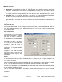
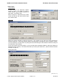
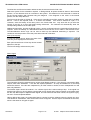
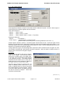
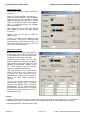
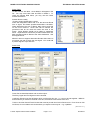
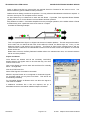
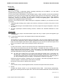
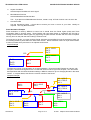
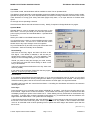
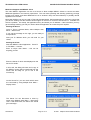
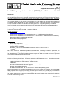
TECHNICAL BULLETIN G16/86
Issue 1
Stephen Parascandolo [M1161]
Model Railway Computer Control Centre (MRCCC): User Guide
JUL 2005
Introduction
Model Railway Computer Control Centre (MRCCC) is a Windows software application created to provide a
user interface and interlocking for the model railway that closely replicates real modern UK signalling practice.
It currently only supports the MERG Remote Panel Control (RPC) hardware system in RS232 single-drop
mode.
This Technical Bulletin (TB) is intended to form the basis of a User Guide from which the basic operation of
the software can be understood. It is not a comprehensive manual covering all scenarios, but should enable
the user to be able to make a start and learn the rest by experience. A Signalling Glossary is included.
(See TB G16/85 for an overview of the MRCCC software, and a list of references and suggested reading.)
Downloading and Installing
To obtain the software, either download, or request a CD direct.
Website Instructions
Visit http://www.bwwmrc.co.uk/mrccc
1. Use the Link to download the .NET Framework version 1.1* (20MB download from Microsoft)
2. Use the Link to download the .NET Framework ver 1.1 Service Pack 1* (10MB download from Microsoft)
3. Download the MRCCC Installer (1MB download)
4. Run the MRCCC Setup application
* If required
CD Instructions
1. Run the Setup Application
2. Accept messages to install the .NET Framework version 1.1*
3. Complete MRCCC Installation
4. Run dotnet1_1SP1.exe to install the .NET Framework version 1.1 Service Pack 1*
* If required
Both options result in a Model Railway folder on the Start Menu containing the MRCCC Application, the
MRCCC Client (see page 12), and the Technical Bulletins covering the software and the Horton application.
The default directory is \Program Files\MRCCC and a \samples sub folder will contain the Horton Layout that
may be useful to learn from and experiment with.
System Requirements
MRCCC is built using Visual Basic .NET, which requires the .NET framework to run. Microsoft recommends
the following for the framework (I have used slightly less):•
133MHz Intel Pentium or AMD Opertron, Athlon64 or better
•
128MB RAM
•
150MB Hard Disk space (including 40MB during installation only)
•
800 x 600 screen resolution, 256-colour graphics
•
Mouse or compatible pointing device
•
MS Windows XP, 2000 SP 4, ME, 98, NT4: SP 6a or Server 2003 operating system
Experience has shown that the MRCCC application works best on a faster PC (2GHz or above with 256MB
RAM), especially when a large layout is being operated at speed. Slower PCs, providing they can handle the
.NET framework, are more than adequate for data preparation or use as MRCCC Clients.
The software supports up to 1280x1024 screen resolution layouts. It is easier to run layouts that fit wholly on
the screen without having to scroll.
[Cont. over >>>]
© 2005 Stephen Parascandolo & MERG
Page 1 of 14
G16/86/1/1
TECHNICAL BULLETIN G16/86
MODEL ELECTRONIC RAILWAY GROUP
Modes of Operation
MRCCC has three distinct modes of operation, changed using the Mode Menu:1. Design Mode allows the user to create and modify the track and signalling layout and interlocking
conditions. Full validation is carried out at each step and errors reported to the user. MRCCC always
starts up and closes from design mode (on exit, the mode change will be automatic if required).
You cannot enter Test or Operate Mode if errors exist in the layout data. Use Interlocking Menu – Check
Data if you find the Test and Operate Mode options are disabled on the Mode Menu.
2. Test Mode allows you to simulate the inputs of the layout. You can set Routes and operate the
signalling as you would in operate mode and the interlocking will respond accordingly.
3. Operate Mode allows the user to control the layout. After selecting the Mode, choose the COM Port,
and Link speed for your system and you are in control. It may take a few seconds for the layout states to
update the display.
Design Mode
File Open and Save
At any time in Design Mode, you can choose to save your current layout. Standard Windows File – Save or
File – Save As options are available. To Open a saved file, use File – Open. Files are saved as .MRC files.
File – New creates a new, blank, layout. MRCCC will prompt you on exit or New to save your existing layout
if it has been modified.
RPC Configuration
The first data to enter with a new
layout should be the RPC configuration. Use RPC Hardware – Configure
and enter the number of modules of
each type. The software will calculate
the number of bits which are available
to be referenced.
Note, that if you return to this dialog,
the values will be at zero again, and
will require re-entering. You are not
permitted to reduce the number of
modules if you have referenced bits,
which would no longer be available
afterwards.
A simple bit Test Utility is provided
using RPC Hardware – Test. This will
only work for up to 32 bytes due to the
addressing limitations of Type 3, 4 and
5 messages.
Editing
On opening, the ‘selected tile’ will be in the top left corner, or as close to this as possible if objects in an
opened file are positioned there. The ‘selected tile’ is identified as a blue square with a green outline if there
is no object in that position.
With the exception of Routes and RPC configuration, all objects are placed on a unique tile within the 80x64
tile grid. Only one object can be placed in any tile and all objects will be visible in Design Mode.
Pressing F3, or using Modify – Change Data, will bring up the details on an existing object. Pressing Del will
attempt to delete an object. You can not delete an object that has been referenced by another; in all cases,
an error message will detail the reasons.
Use the Insert Menu to add objects. The following sections detail each object type and the available
settings. At all stages, the software will provide detailed error messages to explain why you can’t do
something.
G16/86/1/2
Page 2 of 14
© 2005
Stephen Parascandolo & MERG
MODEL ELECTRONIC RAILWAY GROUP
TECHNICAL BULLETIN G16/86
Object Types
Track Section
A track section is an electrically isolated
section of track. It is easier to create a
Track Section device before drawing the
track itself – see Design Tips.
Enter a unique ID. If the section has a track
circuit, tick the box and enter the RPC input
bit to read its state.
Plain Line
Select the symbol required to make up the layout. The symbols on the right form fixed crossings for
scissors crossovers. If the track element needs to animate (either route lights or track occupation or both),
you must reference a Track Section by ticking the box and entering the Track Section reference exactly as
you named the Track Section.
If the Track Section has points within it, you must enter Route Animation details to allow the software to
animate the track correctly. Tick the box and enter up to three point references. (See the Route Animation
example on page 10.)
Points (Turnouts)
[Cont. over >>>]
© 2005 Stephen Parascandolo & MERG
Page 3 of 14
G16/86/1/3
TECHNICAL BULLETIN G16/86
MODEL ELECTRONIC RAILWAY GROUP
Track Section and Route Animation references are the same as that for Plain Line.
Select the Symbol for the orientation required. In Design Mode, all points should be drawn in their Normal
position, i.e. the direction which is not broken in the symbol. The default is for the Horizontal or Vertical to
be the Normal position with Reverse being the diagonal. If the diagonal on the mimic is the Normal
position, tick the ‘Swap N/R’ box.
The Point must be given a Unique ID. If the point is controlled via an RPC output bit, enter this in the RPC
Bit box. If this is not required, enter ‘-1’ to inform the software. If the Point is worked as a pair, i.e. a
crossover, enter the identity of the other point in the ‘Works With’ box. Only enter this as you draw the
second of the two as it must exist before being referenced. The software will automatically enter the
corresponding reference in the other point.
Additional interlocking, beyond the Route locking, can be configured using the Interlocking Data boxes as
required. Enter the Identity of a Miscellaneous device that must be True or False in the relevant boxes.
The Miscellaneous device logic can be used to build up the additional interlocking if required. The
conditions must be proved to move the points either Normal or Reverse.
Point (Turnout) Key
A Point Key device simply allows the state of the
Point Key to be displayed on the screen.
Each point should have a Point Key device located
adjacent to the tips.
The Point ID simply references the point.
Shunt Signal
The orientation should be selected and a unique signal identity entered. If the signal is connected to RPC
outputs, enter RPC addresses. If two bits are required (Address 1 for Stop and Address 2 for Proceed)
should be entered. If the bits are multiplexed by an SD4 module or similar, tick the ‘Multiplexed’ box and
enter only Address 1.
The Default Aspect should be entered – for a Shunt signal, this is almost always Stop. If the signal is a
position light (call on or shunt) aspect mounted with a main signal and it does not display a red aspect itself,
tick the ‘Use Red Aspect of Adjacent Main Signal’ box which ensures that when not set, the symbol is grey,
not red in Test and Operate Modes.
Having defined the signal, the Interlocking Data is required to tell the software when the signal can clear.
This should be entered later, after Routes have been configured. See the Aspect Conditions section later,
which is the same for all types of signal.
G16/86/1/4
Page 4 of 14
© 2005
Stephen Parascandolo & MERG
MODEL ELECTRONIC RAILWAY GROUP
TECHNICAL BULLETIN G16/86
2-, 3-, and 4-Aspect Signals
These signals are identical, except for the number of RPC Addresses required. As with a Shunt Signal, a
unique Signal ID is required, together with the orientation.
Direct RPC Addresses
2-Aspect
1: Red, 2: Green
3-Aspect
1: Red, 2: Yellow, 3: Green
4-Aspect
1: Red, 2: Bottom Yellow, 3: Green, 4: Top Yellow
Multiplexed Addresses
2-Aspect
Use Address 1
3- and 4-Aspect 1: Control Input A, 2: Control Input B
(based on SD4 module being used. Remaining addresses to be set to ‘-1’).
Default Aspects should be entered. Controlled signals should default to Red. Automatic signals should
default to the best aspect they would give if tracks were clear and Controlled signals were at Red, i.e. an
Automatic signal in rear of a Controlled signal should default to Yellow. (See the Signalling Glossary for the
definition of Controlled and Automatic signals.)
Having defined the signal, the Interlocking Data is required to tell the software when the signal can clear.
This should be entered later, after Routes have been configured. (See the Aspect Conditions section on
page 8, which is the same for all types of signal.)
Exit Signal
Isolated Exits are used as the exit for a Route,
which is not a signal. This would be used in
places such as buffer stops or into fiddle yards.
In this case, a grey exit should be used pointing
in the direction of travel. The Default Aspect
should be Red for buffers, but for moves into a
Fiddle Yard, this can be selected to determine
the aspect shown for moves into the yard.
The other use is for Shunt or Call On exits. To
select a subsidiary Route, rather than a main
Route, a separate Shunt or Call On exit should
be provided adjacent to the exit signal. Clicking
on the exit, rather than the exit signal would set
the Call On Route for example. These exits
should be coloured White.
[Cont. over >>>]
© 2005 Stephen Parascandolo & MERG
Page 5 of 14
G16/86/1/5
TECHNICAL BULLETIN G16/86
MODEL ELECTRONIC RAILWAY GROUP
Miscellaneous Input
There can be five types of input – all require a
unique ID.
Switch or Control (different symbols only) –
Select the symbol required. This produces a
switch that you click on to operate. If an RPC
address is entered, the virtual switch will also
output to the specified RPC Output address.
Use ‘-1’ to make the function only available
internally to MRCCC.
LED – Reads in from the RPC Input address
and indicates as required. The RPC address
is required.
Hidden – As LED but will be invisible in
Operate Mode.
A Button – Provides an Auto Button Control
on the screen. This can be configured in the
Routes Dialog to associate with a Route. An
Auto button ID must be in the form xxx Auto
where xxx is a valid Signal ID.
Miscellaneous Output
Miscellaneous Outputs are used to build up
custom logic. Each needs a unique ID. Up
to five conditions can be used and either
an AND or an OR of them calculated.
Conditions can be made from any state
known to MRCCC by selecting the device
type, entering the unique device ID and
selecting an appropriate condition to test
for. Only conditions with the Condition
Active box checked are evaluated.
LED type displays as an LED on the
screen if the result is True. Hidden Type
just holds the state internally once in
Operate Mode. Both types can output the
result if an RPC Output Address is
specified.
You can build up lots of these devices to
create more complex logic if required.
However, with MRCCC doing most basic
signalling logic for you, these should only
be required for accessories such as power
switching or Junction Indicators as in the
example on the right.
Routes
A Route is defined as the path from one signal to the next signal on the chosen path. It is not Start to
Destination for the train. All Routes need to be configured and the interlocking between them defined.
Use Interlocking Menu – Routes Table to start.
G16/86/1/6
Page 6 of 14
© 2005
Stephen Parascandolo & MERG
MODEL ELECTRONIC RAILWAY GROUP
TECHNICAL BULLETIN G16/86
Route Table
To add a Route, click New. Once added, it will appear in the
list. You may come back later and Edit or Delete it. To
check the Routes Data alone, you may use the Check
Routes Data button.
Routes IDs are usually
R<entry signal><designation><class>
where the designation starts with A for the left-most Route
from a signal, and labels possible destinations clockwise.
Class determines the type of Route: Main, Shunt, and Call
On are most common. Shunt and Call On Routes are
permissive and do not check all tracks are clear in the
Route. Shunt Routes should not be taken by passenger
trains. Separate Exits should be provided where there is a
Main and Shunt/Call On Route to the same destination. See
Exit Signal above.
MRCCC does not support Alternative Routes where there is
more than one path to reach the next signal. You could add
a pseudo signal to cope with this.
Route Card
Route IDs are described above and must be unique.
The Entry Signal and Exit Signals must be entered.
Conflicting Routes must list all Routes which conflict with this one – i.e. can not be set together. MRCCC
ensures that if you reference a Route in this box, that Route must reference this one.
Tracks to be Clear lists all Track Circuits that must be proved clear for this Route to set. For a Shunt or Call
On Route, do not include track circuits where you expect a train may be – e.g. a platform.
[Cont. over >>>]
© 2005 Stephen Parascandolo & MERG
Page 7 of 14
G16/86/1/7
TECHNICAL BULLETIN G16/86
MODEL ELECTRONIC RAILWAY GROUP
Points to Move must list any points which are required Normal or Reverse for this move to occur. You
should include any points needed for flank protection.
Additional Route Setting Conditions are optional. You may reference Miscellaneous devices as required. A
common use may be if an Acceptance Slot is wanted.
An Auto Button may be referenced to work with this Route. If provided, Train Operated Route Release
(TORR) will not occur for this Route if the Auto Button has been pressed.
Early Release Condition – Somewhat simplified from the prototype operation, this condition allows a Route
to release early once a particular track circuit clears or occupies.
Consider the following example:-
Train x is signalled from Signal 1 to Signal 2 at the end of a station platform. The train stops at the station.
As the train has not cleared all the track circuits within the Route, the Route stays set. Train y is now
waiting at Signal 1 and wants to go to Signal 3. This Route is clear but the original Route is still set.
There must be a method for the initial Route to timeout once the train arrives at the platform so a second
Route can be set.
Rather than a timeout, the Early Release Condition allows it to release when clear, or if the train reaches
the far end of the platform.
Aspect Conditions
Once Routes are entered and all the necessary interlocking
details entered, the signals need to be told that they can clear
when a Route is Set.
Click on the Signal you want to work with and Press F3 or Modify
Menu – Change Data.
Now click, Edit Route List.
Select if the Signal is Controlled or Automatic.
MRCCC requires Routes to be configured for Automatic Signals.
An Automatic signal can only have one Route. This will be set
automatically at startup.
For Controlled Signals, all Routes which can allow the signal to
clear must be entered.
If additional conditions like a Slot are required, set up a
Miscellaneous device and add an additional Aspect Condition.
G16/86/1/8
Page 8 of 14
© 2005
Stephen Parascandolo & MERG
MODEL ELECTRONIC RAILWAY GROUP
TECHNICAL BULLETIN G16/86
Design Tips
Prerequisites
First of all, the basics.
Before trying to apply a reasonably realistic signalling interlocking such as MRCCC, you must have
signalled the layout prototypically in the first place.
For the most accurate representation of the signallers display, realistic operation and the best operational
performance, the layout must be provided with sufficient track circuits for the track layout. Saving a few
pounds on less wire and modules could really restrict operations once you apply a proper signalling
interlocking. Read up on the theory, get an expert in or study real signalling plans. (See the list of
references and suggested reading in TB G16/85.)
Secondly, you must document this. Before starting the configuration of MRCCC, you will save a lot of time
if you have:1. A signalling plan showing points, signals, track sections, track layout, normal lie of the points, and all
identities.
2. A Route Table listing all the available Routes, their Entry Signal, Exit Signal, Designation, Class and
any notes.
3. The RPC Input/Output schedule showing functions, modules and calculated addresses for each
function.
Where to start
TIP – Start with a very simple, small demonstration layout with only a couple of points and signals to get
the hang of it.
TIP – Look at the Horton Layout in the /samples folder for ideas and inspiration.
1.
Screen Layout
The first task is to set out the screen layout so it fits neatly. Set your screen resolution to that which
you need when operating the layout, maximize the MRCCC window and insert single sections of plain
track to mark the edges, ends of bits of track, spacing etc so you can be sure the whole layout will fit
before you’ve spent a couple of hours putting two thirds of the layout in.
2.
Track
For each track section, create a Track Section device first, positioned above the line itself.
Then start at one end and set up the first track element. Complete every entry, including the Track
Section reference and Route animation. If the Track Section or the Points referenced are not yet
created, simply leave the relevant box unchecked. This will allow you to enter the data first. You can
check the boxes later once they have been added.
TIP – For each type of object when you go back to the dialog box another time, it remembers your
previous entry. So start at one end, enter all the information, and move on to the next tile. As
you work along a track section, you won’t need to re-enter things each time. This also applies if
you call up the dialog using F3 or Modify – Change Data, so use this to copy items.
Create the Points as required, completing as much as possible. Save effort by doing both ends of a
crossover together. Add Point Keys to each Point Tip if desired.
Remember to leave space for Signals where required.
3.
Signals
Once the track is done, add the signals and exits, but leave the Aspect Information until later.
4.
Routes
Complete the Routes, based on your pre-prepared Routes Table. Work through systematically,
entering all conflicting Routes and point calls. Use the Check Routes Data button to see what is left to
do.
[Cont. over >>>]
© 2005 Stephen Parascandolo & MERG
Page 9 of 14
G16/86/1/9
TECHNICAL BULLETIN G16/86
5.
MODEL ELECTRONIC RAILWAY GROUP
Aspect Conditions
Add the Aspect Conditions for each signal.
6.
Miscellaneous Devices
Add the Miscellaneous Devices last.
TIP – If you plan lots of Miscellaneous Devices, create a ‘map’ in Excel of which one is in which tile.
7.
Check the Data
Use the Interlocking Menu – Check data to ensure you have no errors in your data. Modify as
required. This may take some time!
Route Animation Example
Route Animation is used by MRCCC to learn how it should show the Route Lights (white) and Track
Occupation (Red) in junction areas. Those familiar with real signal boxes or simulations like PC-Rail or
SimSig will know that the White Lights only light along the path the train will take and the Track Occupation
will only show on the path the train is taking if a Route is set.
To know how to do this, you must configure Route Animation and tell MRCCC how the segment of track you
are creating relates to points within the same track section. Route Animation is done on a per section basis.
It does not matter which points are in an adjacent track section.
Simple Example
Ref 1: 123 R
Ref 2:
Ref 3:
123
Ref 1:
Ref 2:
Ref 3:
Ref 1: 123 N
Ref 2:
Ref 3:
Ref 1:
Ref 2:
The best way to learn route animation is via experimentation. Enter the Simple Example as a layout, with
one point, 123 and three signals for the 2 routes that would run left to right over the point. Use Test mode
and experiment with the Route Animation settings. MRCCC caters for up to 3 diverging Routes in the same
section. In complex areas, start from the common section of the Route.
Complex Example
Ref 1:
Ref 2:
Ref 1: 456 R
Ref 2:
Ref 1: 123 N
Ref 2:
Ref 3:
Ref 1: 123 R
Ref 2:
Ref 3:
G16/86/1/10
Ref 1: 456 R
Ref 2: 789 R
Ref 3:
789
123
456
Ref 1:
Ref 2:
Ref 3:
Ref 1:
Ref 2:
Page 10 of 14
Ref 1: 456 R
Ref 2: 789 N
Ref 3:
Ref 1: 456 R
Ref 2:
Ref 3:
Ref 1: 456 N
Ref 2:
Ref 3:
© 2005
Stephen Parascandolo & MERG
MODEL ELECTRONIC RAILWAY GROUP
TECHNICAL BULLETIN G16/86
Test Mode
If your data is valid, the Mode Menu will be available to enter Test or Operate Mode.
Test Mode is almost identical to Operate Mode except that Hidden Devices and Track Sections remain visible.
Operate the layout just as you do for Operate Mode, but instead of having hardware connected, Click on the
Track Sections to Occupy (Left Click) and Clear (Right Click) them, or on Input devices to simulate other
inputs.
Go through various operating scenarios.
Check that each Route sets and animates correctly. Modify if required in Design Mode and try again!
Operate Mode
Operate Mode is used to operate the layout through to the
RPC Stack. Connect your serial port to the RPC processor,
power up the processor and use Mode Menu – Operate Mode
to connect.
Select your COM Port and Baud Rate and click OK.
You should hear any relays or points initialising and the track
indications will clear. You are now in control and the screen
should react to any input changes or track occupation.
Any Auto Routes will try and set, but may fail if there are trains
on the track. Set them manually when available.
Route Setting
Left Click on the Entry Signal, and then Left Click on the
Exit Signal. If the Route is available, it will set and you
should see the aspect change. If it is not available, it will
display an error message telling you why it failed to set.
Should you press an entry and change your mind, clicking
in free space will reset the Route setting to allow a new
entry to be selected.
Trains will cancel Routes behind them as they clear track
sections (TORR).
If you need to cancel a Route, Right Click the entry signal. Beware, there is no Approach Locking applied in
MRCCC, so ensure you stop the train!
Auto Buttons
If you want the same Route time and time again, or if you are running trains round in circles, you can avoid
the need to set Routes each time by setting an Auto Button if you provided one in the data. This will prevent
TORR from taking place, and as soon as the track sections are clear again, the signal will reclear.
Cancelling the Route will also cancel the Auto Button. Cancelling the Auto Button will result in the next train
releasing the Route.
Point Keys
Point Keys allow you to manually move points individually (or as pairs). Left Click on the point tips to lock
them Normal. Right Click to lock them Reverse. Once locked, the Point Key symbol, if entered in the data
will display showing the points to be locked N or R. Route Setting will only be allowed in the direction they
are locked. To Unlock them, press the opposite mouse button; e.g. if locked Normal with the Left button, the
Right button will release them. The symbol will now disappear.
A special feature built into MRCCC and most definitely NOT on the prototype is that the point key bypasses
the check on the track circuit being clear over the points. This is very useful in case of failure of the track
circuit or an essential need to bend operating rules to permit that extra wagon that doesn’t quite clear the
track circuit.
[Cont. over >>>]
© 2005 Stephen Parascandolo & MERG
Page 11 of 14
G16/86/1/11
TECHNICAL BULLETIN G16/86
MODEL ELECTRONIC RAILWAY GROUP
Multi-User Support and MRCCC Client
The main MRCCC Application can act as a Server to allow multiple MRCCC Clients to connect as either
additional signallers or as read-only supervisors. This can make operating and shunting (switching) on large
layouts much easier, and allow additional PCs on a wireless LAN (Local Area Network) or possibly remote
signallers over the Web.
Multi-User facilities can only be used in Test and Operate Modes. Before attempting to use them, ensure that
you have a working LAN and relevant access rights on the PCs to connect to the server PC. Firewalls can
also be a problem. On startup, the application will try and obtain your IP address. If this is blocked, you may
get a message advising you that you need to allow the application to access the port it requires.
Starting the Server
Once in Test or Operate Mode, select Multiple User
Menu – Start Server.
If you get the message on the right, you are ready to
accept clients.
Note your IP address which you will need for your
clients.
Starting the Client
Start the MRCCC Client Application. Press F1
or File Menu – Connect.
Enter a unique User Name – this can be
anything you like.
Enter the Server IP which was displayed on the
Server PC earlier.
If all is well, the dialog will clear and a copy of
the MRCCC screen will be transferred from the
server and be ready for you to use in the
normal way.
On the Server PC, you can check which users
are connected by using Multiple User Menu –
Display Users.
The Server PC can disconnect a client by
name using Multiple User Menu – Disconnect
User. If the Client exits, the Server PC should
get a message:-
G16/86/1/12
Page 12 of 14
© 2005
Stephen Parascandolo & MERG
MODEL ELECTRONIC RAILWAY GROUP
TECHNICAL BULLETIN G16/86
The Client may be switched to Supervisor Mode using Mode Menu – Supervisor. This blocks any mouse
clicks on the control screen.
Any error messages such as ‘Route failed to set’ are sent to the user that made the request.
Separate Route Setting Entrance/Exit pairs are recorded by each user. All requests are sent to a central
queue on the server. This is serviced on a first come, first served basis. As a result, if two users perform
conflicting operations, the one who got the request in the queue first will get the Route, and the second will
get an error message.
All screen changes are sent to all clients.
Acknowledgments
MRCCC wouldn’t be possible without Gordon Hopkins whose excellent RPC hardware system allows the PC
to communicate with the layout. Gordon’s help and advice have been essential.
Graham Plowman’s Solid State Interlocker (SSI) showed what could be done with computer control, proved all
my hardware and gave me the idea of using three modes of operation.
The Beckenham and West Wickham MRC for allowing me to develop Horton with RPC and computer control.
GE Transportation for providing me with access to many real signalling centres and technical standards
together with professional signalling training.
Signalling Glossary
Route – The path between an ENTRY signal and the next signal the train will come to (the EXIT signal).
Aspect – The colour of the signal (Red, Green, Single Yellow, Double Yellow, Stop or Proceed).
Normal – The direction that a set of points are usually left in – this is normally the main line or directed to
avoid conflict with another train. Normal is not always the ‘straight’ direction either on the physical point or on
the schematic diagram. Points are always shown in their Normal position in Design Mode and on signalling
plans.
Reverse – the opposite of Normal.
Track Circuit or Section – A means of detecting the presence of a train, usually in an electrically isolated area
of track. On the model railway, a FTC (Floating Track Circuit) module or perhaps a ToTI (Train on Track
Indicator). Optical detectors could also be used.
Screen Colours:Grey Track – Normal track.
White Track – Route locked over the track.
Red Track – Train on the track.
Automatic Signal – Signal that does not require a Route to be set by the signaller. It must be on plain track
with no point work.
Controlled Signal – Signal that can only clear if a signaller sets a Route from it.
Call On or Shunt Signals – Proceed aspect shown as two white lights at 45 degrees. Aspects are permissive
– the line ahead is not always proved clear through to the next signal, just correctly set. Drivers must be able
to stop short of any obstruction.
Point Key – Manual control of a set of points (or pair) to move the point without having to call a Route. Useful
for maintenance work or to protect engineering work. A Point Key has three states – Normal, Reverse and
Centre. Centre is the default and the point is then available for Route setting in either direction. Normal or
Reverse lock the points in that direction and Route setting will not be able to move those points.
Slot – A form of interlock with another signal box. One of your signals may be ‘slotted’ with an adjacent box,
such that before it clears, you have to do half, and the other box does half. In a mechanical box, this may be
a lever in each box and a mechanical Slot. In a more modern box or VDU system, an acceptance switch or
control on the VDU may act as the Slot. The Slot is usually indicated in the other box so you know you have
the acceptance from the other signaller.
[Cont. over >>>]
© 2005 Stephen Parascandolo & MERG
Page 13 of 14
G16/86/1/13
TECHNICAL BULLETIN G16/86
MODEL ELECTRONIC RAILWAY GROUP
TORR – Train Operated Route Release. As trains traverse the Route, the Route locking and hence, lights
clear behind the train. This occurs unless the Auto Button has been operated. Due to sectional Route locking
not being implemented in MRCCC, the Route remains locked until the train clears the last track in the Route
or the Early Release condition is met, or the signaller Cancels the Route.
Classes of Route
Main (M) – Normal Route which on a real railway would have a full safety overlap. A Main Aspect (Yellow,
Double Yellow or Green) would clear for the driver.
Warner (W) – Used in conjunction with Approach Release to permit a reduced overlap to be used. A Main
Aspect would clear for the driver but only as the train has slowed and is approaching a red signal. No
Warner Exits are provided for in MRCCC, as I have assumed that overlaps are not provided on most model
railways.
Shunt (S) – Used for shunting moves – these can not usually be for passenger carrying movements. Shunt
Routes are usually permissive and the line ahead is not proven to be clear. Drivers receive two small white
lights and must be able to stop clear of obstructions.
Call On (C) – Used if passenger trains need to enter occupied platforms such as when joining together
Multiple Units or sharing platforms. Drivers receive two small white lights and must be able to stop clear of
obstructions. These should be separately selected by the signaller using a Call On Exit button adjacent to
the main exit signal.
Route identities
Routes are usually named after the entry signal. This is followed by a letter for the destination and the class in
brackets. The destination letter is sometimes omitted if there is only one Route from the entry signal, but
otherwise starts at A for the Route which will ultimately result in the train being as far to the left as possible
from that entry signal. The next Route is B and so on.
A typical two-way divergence from an entry signal 10 would result in R10A(M) and R10B(M). If this was a
large station where Call On Routes were provided, and if there was a siding on the far right, this would result
in R10A(M), R10A(C), R10B(M), R10B(C) and R10C(S).
Junction Indicators (feathers or lunar lights)
These are provided to tell the driver that a diverging Route is set. The highest speed Route does not usually
have an indicator provided. The main signal illuminates on its own. Routes to the left of the fastest Route,
receive an indicator at 45 degrees to the left for the first Route, 90 degrees for the second and occasionally
135 degrees for the third. The same applies to the right.
Up to 6 Positions are possible. Those on the left from the top are Position 1 (45 degrees), 2 (90 degrees) and
3 (135 degrees), with those on the right being 4, 5, and 6. If the diverging speed is the same, both Routes
sometimes receive indicators.
If there are more Routes than this, theatre indicators are provided (which are awkward in model form!).
G16_86_1.doc
G16/86/1/14
Page 14 of 14
© 2005
Stephen Parascandolo & MERG