1
The Front Panel Overview
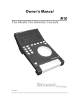
The front panel has a large simple easy to read display, an encoder for adjusting and selecting settings, 6
keys that are labeled for their use, and a power stand by switch that will set the M1 in to low power mode
and mutes the outputs.
The Rear Panel Overview
Looking at the rear you will find on the left and right side the analog output sections, each with their own
balanced and unbalanced outputs, and level adjustment set screw. In the center input section are the 4
digital audio inputs, AES (XLR connector ) SPDIF ( RCA connector ) Toslink ( optical connector ) and
USB. There is a small jack below the fuse and this is for a trigger input to remotely place the M1 in
standby from a Pre Amp or other system controller. The main power on of switch and AC fuse is at the
rear, and note that the front panel and the trigger in are used to set the M1 to stand by. Full power on off is
done from the rear panel.
Setup and Operation
AC power and the M1
The AC power is connected at the rear of the unit; the filtered AC inlet also has the main power on off
switch. This filtered inlet helps provide clean AC power to the M1s power supplies and as well will
prevent any digital noise from the M1s digital processing section from going back out the AC inlet to
contaminate your mains. Take note that since the M1 utilizes linear power supplies care should be taken to
use only the power range indicated on the unit, other wise damage can occur to the power supplies and
other circuits in the M1. Please note and adhere to any voltage indications on the outer box, rear panel or
chassis all of which will indicate how the M1 is set at manufacture.
Note that the main AC power switch is at the rear and the front panel switch is a low power consumption
stand by switch. For complete power on of you must cut power with the rear panel switch or from an
external AC power on off switch that may be used to power other devices in your setup.
4