1
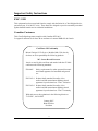
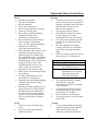
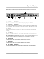
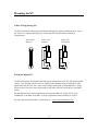
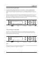
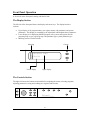
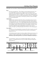
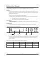
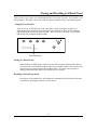
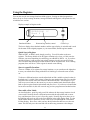
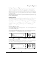
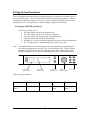
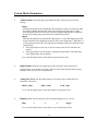
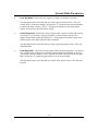
Owner’s Manual M7 The Model Seven Stereo Digital Reverb Processor Rev 5.02.08 Unpacking and inspection After unpacking the M7 save all packing materials in the event you ever need to ship the unit. Thoroughly inspect the M7 and packing materials for any signs of damage in shipment. Report any damage to the carrier at once. Precautions The Bricasti Design M7 is a rugged device with extensive electrical protection. However, reasonable precautions applicable to any piece of audio equipment should be observed. y Always use the correct AC line voltage. Refer to the power requirements section of the manual. Using the incorrect AC line voltage can cause damage to your M7, so please check this carefully before applying power. y Do not install the M7 in an unventilated rack or directly above any heat-producing equipment like power amps, tube preamps or compressors, etc. Maximum ambient operating temperature is 40 C. Exceeding the maximum ambient temperature may cause the M7 to enter thermal shutdown and stop processing sound as a safety precaution, and may cause damage to the internal processors and components. y The M7 is built with a temperature-controlled cooling fan, designed to run at a slow quiet speed under normal ambient temperature operating conditions. To ensure that the fan runs at low, please take care where the M7 is installed. Install it in a cool place and it will be quiet. Install it in a hot place, the M7 will be hot, and the fan will run faster, creating more noise. y Never attach power amplifier audio outputs or other power sources directly to any of the M7 connectors. y To prevent fire or shock hazard, do not expose the M7 to rain or moisture. Notices In the interest of continued product development, Bricasti Design reserves the right to make improvements to this manual and the product it describes at any time and without notice. Copyright 2007 Bricasti Design LTD 123 Fells Ave Medford MA 01255 USA 781 306 0420 bricasti.com All Rights Reserved This publication is protected by copyright and all rights are reserved. i Important Safety Instructions EMC / EMI This equipment has been tested and found to comply with the limits for a Class B digital device, pursuant to part 15 of the FCC rules. These limits are designed to provide reasonable protection against harmful interference in residential installations. Canadian Customers This Class B digital apparatus complies with Canadian ICES-003. Cet appareil numerous de la classe B est conforme a la norme NMB-003 du Canada. Certificate Of Conformity Bricasti Design, 123 Fells Ave., Medford MA, USA, hereby declares on own responsibility the following products: M7 - Stereo Reverb Processor -that is covered by this certificate and marked with the CE-label conforms to the following standards: EN 60065 Safety requirements for mains operated electronic and related apparatus for household and general use EN 55103-1 Product family standard for audio, video, audiovisual and entertainment lighting control apparatus for professional use. Part 1: Emission EN 55103-2 Product family standard for audio, video, audiovisual and entertainment lighting control apparatus for professional use. Part 2: Immunity With reference to the regulations in the following directives: 73/23/EEC, 89/336/EEC January 2007 Brian S Zolner President ii Important Safety Instructions Notice! • Read these instructions. • Keep these instructions. • Heed all warnings. • Follow these instructions. • Do not use this apparatus near water. • Clean only with dry cloth. • Do not block ventilation openings; install in accordance with manufacturer’s instructions. • Do not install near any heat sources such as radiators, heat registers, stoves, or other apparatus (including amplifiers, pre amps, tube compressors) that produce heat. • Do not defeat the safety purpose of the polarized or grounded type plug. A polarized plug has two blades with one wider than the other. A grounding type plug has two blades and a third grounding prong. The wide blade and prong are for your safety. If the provided plug does not fit in your outlet, consult an electrician for replacement of the obsolete outlet. • Protect power cord from being walked on or pinched. • Use only attachments/accessories specified by the manufacturer. • Unplug this apparatus during lightning storms or when unused for long periods of time. • Refer all servicing to qualified service personnel. Service is required when the apparatus has been damaged in any way, such as by being dropped, exposed to rain, liquid being spilled on it, or otherwise does not operate normally. Warning! • To reduce the risk of fire or electrical shock do not expose this equipment to dripping or splashing water and ensure that no objects such as vases are placed on the equipment. • This apparatus must be earthed. • This equipment requires the correct AC line voltage as set by the manufacture and is not auto sensing. • Use a three-wire grounding-type line cord like the one supplied with this product. • Be aware that different operating voltages require the use of different types of line cords and attachment plugs. • Check the voltage in your area and use the correct type. See table below: Service • There are no user serviceable parts inside. • All service must be performed by qualified personnel. Caution • You are cautioned that any change or modification not expressly approved in this manual could void your authority to operate this equipment. Voltage 110-125V 220-230V 240V • • • • iii Line plug standard UL817 and CSA C22.2 no 42 CEE 7 page VII, SR section 107-2-D1/IEC 83 pg C4 BS 1363 of 1984 Specification for 13A fused plugs and switched and unswitched outlet plugs This equipment should be installed near the socket outlet and disconnection of the device should be easily accessible. To completely disconnect from AC mains, disconnect the power supply cord from the AC receptacle. Do not install in a confined space. Do not open the unit -risk of electrical shock inside. Table of Contents Introduction v 1. Installing the M7 Front Panel Overview Rear Panel Overview Mounting the M7 Power Requirements Analog Audio I/O Setting Digital and Analog I/O 1-0 1-1 1-2 1-3 1-4 1-5 1-6 2 Operation Front Panel Operation Selecting Preset Programs Editing a Preset Program Storing and Recalling edited programs Setting System Parameters The System Mode Parameters 2-0 2-1 2-2 2-3 2-4 2-7 2-8 3 The Reverb Programs Reverb Types Reverb Parameters Preset List 3-0 3-1 3-2 3-4 4 Upgrades Upgrading the M7 4-0 4-1 5. Specifications Technical Specifications 5-0 5-1 Introduction Congratulations on the purchase of your new M7 Stereo Reverb Processor. You are about to begin using the most advanced digital reverb processor available. We at Bricasti Design have set out to design the world’s best digital processors and to offer the finest products made for the professional audio market. Hand Crafted Design Our products are hand crafted in the USA. We use the finest materials to create devices with an elegant look, a great feel, and the durability to stand up to the most demanding installations. A product you can be proud of. Use We designed the M7 for the Professional Audio Engineer: Easy to use, quick to get at great sounding presets, hot keys to save that favorite program with a button push, and a bright easy to read display, legible at a distance and at any angle. Technology We use the latest digital technologies, the best DSPs, state of the art A/D conversion, together with uncompromising great classic analog design, to create a modern but classic product. Sound We made this product to create sound, and we do this with our innovative reverb algorithms. From Classic to New, we provide you with a palette of great sounds to hang in your mix. Applications For the Studio, the M7 provides both the standard AES 192k single wire digital interface and great analog conversion. For live applications we designed an easy interface, and most importantly, a display that can be read at any angle, at a distance and in any light, even daylight. We at Bricasti Design thank you. The latest manual can always be downloaded from our web site: www.bricasti.com Please feel free to contact us there if you have any questions regarding this manual or the product. v 1 Installing the M7 Installing the M7: 1. The basic controls and functions 2. Mounting and installation 3. Mains power requirements 5. Setting the analog audio levels 6. Digital audio connections 1-0 Front Panel Overview 10 11 M7 C o n+ c e r t H a l l Hal ls prog Reg System Store Edit Enter 7 8 1 Input 1 2 3 4 5 6 1. Input Level Analog audio input level adjustment. Precision, re-settable stepped analog audio input knob in 2dB steps from +8 dbm to +24 dbu. 2 3 4 tap 9 12 13 14 8. Enter Key Press to confirm operations like loading a selected program. 9. Store Key Press to store an edited program in a register. 2. Level Meters Displays the current input level, or output level, software selectable. 10. Program Key Takes you to the program select mode. Use the adjust knob to scroll through programs, press Enter to select. 3. Display Display for the program, edit parameters, and system parameters that are being adjusted or selected. 11. Reg Key Takes you to the user register bank where edited presets are stored and labeled. 4. Cursor Up/Down Keys Controls lower display, selects reverb effect parameters, program banks, system parameter types, register banks. 12. Favorite Keys Pressing and holding one of these keys will store your current running program in its current state. Pressing once quickly will recall the program. 5. Program Select and Effect Adjust Knob Controls upper display and scrolls through programs in the program mode, adjusts effect parameters in edit mode. 13. Tap Key Used to “tap”-in time based parameters 6. System Key Takes you to the system menu to select system setup parameters. 14. Power on off switch Left position is OFF, right position is ON 7. Edit Key Brings you to the effect edit page of the current running program. 1-1 Rear Panel Overview Rear panel overview and descriptions highlighting important connectors and ventilation areas: 8 AC Power 100-240V Midi 1 2 3 Analog In Digital I/O AES IN AES OUT 4 remote loop thru 5 Left In Handcrafted in the USA Right In 6 CE Analog Out Left Out Right Out 7 1. Fan Outlet WARNING! The fan exhaust outlet. Do not block or obstruct this opening. Keep clear and clean. 2. AC Inlet/Fuse WARNING! IEC standard grounded AC power inlet with fuse. Fuse must be the correct type for the voltage set, see rear panel. APPLY ONLY THE AC VOLTAGE AS SET BY THE MANUFACTURER. 3. MIDI I/O MIDI in and out. These have no function for V1 and are reserved for future enhancement and functions. 4. AES Digital I/O Balanced AES single wire digital I/O. Self clocking, supports sample rates from 44.1k to 192k. 5. Remote / Remote loop thru RS 422 serial port for the dedicated M10 remote console. Provides control data and power for the remote. Loop through connector is for connecting up to 4 M7 mainframes to one remote. 6. Analog Outputs 2 Balanced analog audio outputs on industry standard XLR type connectors. 7. Analog Inputs 2 Balanced analog audio inputs on industry standard XLR type connectors. 8. Rear Air Inlets WARNING! Fresh air inlets from the rear panel. DO NOT BLOCK OR OBSTRUCT as overheating may result. 1-2 Mounting the M7 Cables–Wiring-Analog I/O The M7 has balanced analog inputs and outputs following the industry standard practice of pin 2 hot. Below is a diagram showing how to connect the M7 in balanced and un-balanced configurations: XLR to XLR Balanced XLR to Jack Balanced XLR to Jack Un-Balanced 2 1 3 1 2 3 1 2 3 1 2 3 Wiring the Digital I/O The M7 has balanced AES digital inputs and outputs and should be used only with balanced AES sources. Care should be taken to only use cabling for the installation that is designed for AES digital audio data, and not “mic” cable or other analog audio patch or instrument cables. Using incorrect cables can cause clicks and dropouts in the audio of the M7 and yield poor, unreliable results. For this application we recommend Reference Laboratories RAC 01 or RAC 02 for fixed installations, or the RMC 08 or RMC 10 for live applications where flexibility is needed. For more info about their products, contact them at: www.referencelaboratory.com 1-3 Mounting the M7 How to Mount the M7 The M7.0 measures 19” wide by 1 ¾” high by 10” deep. It can rest on any surface or table, or can be mounted in a standard 19” relay rack. Do not install the M7 directly above any equipment that produces significant amounts of heat (such as power amps, or tube compressors, eq’s, mic pre’s etc). Maximum ambient operating temperature is 40C and care must be taken to mount the M7 in a cool place. Ventilation is critical to a long, trouble free life for your M7. The M7 has a temperature controlled cooling fan and tuned ventilation for optimal cooling at low and very quiet fan speeds. Care must be taken not to block the ventilation holes in the sides and rear of the chassis. Doing so could cause the M7 to overheat, not perform as specified, and shorten its life. Although the M7 is a 1U high product, we recommend allowing a minimum of a half a rack space above and below the M7 when mounting it, and the use of ventilated rack fillers, making the installation a minimum 2U. This will allow for the best thermal performance and longest product life. If the M7 is mounted in a rack or road case, we recommend that you provide support for the rear of the unit during transport to prevent possible damage from severe mechanical shock. Also, care should be taken for proper venting in such an enclosure as suggested above. Power Requirements The M7 is equipped with a three pin IEC connector and detachable power cord, providing chassis ground to the AC mains line. The M7 is designed with two power supplies: a separate linear analog power supply for the analog section and a state of the art digital power supply for the digital section. Both can be operated at any voltage from 100-240 Vac., 50 or 60 Hz, but care must be taken if a voltage change is required. The unit is supplied configured to the correct voltage and power cord for the country of destination and local power. If you take your unit to another country with different line voltage you must change the fuse and internal power supply jumper for the linear supply and use the correct power cord for the voltage Warning! DO NOT APPLY POWER OTHER THAN WHAT IS SPECIFIED ON THE UNIT AS SHIPPED FROM THE MAUNUFACTURER. DOING SO WILL CAUSE DAMAGE TO THE POWER SUPPLIES AND VOID YOUR WARRENTY. If a change is required, contact your dealer or distributor for the correct Bricasti part and technical support. 1-4 Audio I/O Analog level adjustments To obtain the best possible performance from the M7, analog input and output levels should be set with care. Here are some guidelines on how to best set the analog audio levels in and out of the M7. Also, follow this procedure to test the analog or digital I/O performance of the M7 as you will need to bypass any processing to be able to test measure accurately. Be sure to note the original level settings as you should return them to the default values after your test. Setting and Testing the Analog Level 1. Press the System key, and use the cursor key to select Dry Gain. Turn the adjust knob counter clockwise to set the level to 0dB, press Enter to set. Then cursor down to Wet Gain and set to Off, press Enter to set. This will bypass any processing that will make it difficult to measure the levels and also set the internal dry audio path to unity gain. 2. Feed a musical source or a 1k test tone at the maximum peak level that you use in your system into the right and left channels 3. While watching the input display, adjust the input level control on the front panel so that the peak is just short of the topmost LED on the meter display. This will be -6 dB below clipping, and illumination of the top bright red LED is 0 dB. 0 db -6 db -12 db -18 db -24 db -36 db -48 db -72 db Front panel meter level indicator values 4. Set the output level found in the System menu, and select +8 dB, +16 dB, or +24dB to best match the input sensitivity of your mixing console return or the next product in the chain. 5. Note: Upon completion of the setup test, return the settings to the factory default positions as leaving them in high level values can cause the M7 to distort on high level signals. Always allow headroom for the Reverb Process, as it can add up to 10 dB of gain to the signal! Analog Reference Level Matching: Set the system to dry with unity gain as described above. With the cursor keys, step through to the Analog Out Level. Use the knob to set the output level to the +16 dB position. On the front panel, set the Input Level selector to the top center stop position, 12 o’clock (+ 16 dbu ). This will reference the analog I/O to unity. Digital I/O When interfacing the M7 using the AES digital I/O there is no level matching required, as level information is part of the AES digital data stream. If you are testing the digital signal path for integrity and gain, follow the steps described above for setting the M7 to dry. Analog and Digital I/O Settings In a typical installation you may want to connect both the analog and digital connectors and choose which interface you want to use as the application demands, thus there are two ways to set the M7’s audio inputs and outputs. 1-5 Audio I/O Using and setting the Digital Inputs The factory default settings of the M7 I/O are set to analog in. If there is a digital input and output connected to the M7, you must select the Audio Format type and change the internal patching in the M7 to Digital. This will set the M7 to use AES digital in and out as its audio I/O path. Press the System key and use the cursor keys to step through the menu to find Audio Format. Use the knob to select Digital, press Enter to set the value. The digital inputs of M7 will accept any AES single wire data stream with sample rates from 44.1k to 192k and is displayed on the Digital Status display by pressing the down key to move to the next screen. Audio Format Digital EDIT Value Parameter selects parameter Adjusts value ENTER Sets value Using and setting the Analog Inputs If the M7 is set to Analog, follow the same procedure described above to set the digital, but choose Analog. In this mode, the M7 will ignore the digital input and outputs and switch and connect to the analog inputs and outputs. Audio Format Analog EDIT Value Parameter selects parameter Adjusts value ENTER Sets value Note: You must choose to use either the analog or digital audio I/O. You can not mix these formats and use analog in to digital out, or digital in to analog out. 1-6 1-7 2 Operation This chapter describes the front panel controls and functions of the M7 2-0 Front Panel Operation A close look at the front panel, starting with the left side. The Display Section The left side of the front panel houses the display and cursor keys. The display has three sections: • • • Upper display is for program names, user register names, edit parameters and system parameters. This display is controlled by the adjust knob which adjusts these parameters. Lower display is for displaying MODE (program, edit, system, and register) and for program group or type, register groups, edit parameter type, system parameter type. Metering section is on the left side. Metering Cursors Boston Hall Halls Lower display Upper display The Controls Section The right side houses the buttons and controller for navigating the menus, selecting programs, adjusting parameters, saving and recalling user registers and favorites. power prog Reg System Store Edit Enter 1 2 3 4 tap 2-1 Selecting a Preset Program The first thing you may want to do is browse through the preset programs and select one that you want to hear. The “out of the box” default is set to Large Hall 01 in the Hall bank of programs. Prog: Press the Prog (program) key. This will bring you to the program select mode. If you are in another display, such as System, pressing the Prog key will bring you to the program select state and display the last program viewed or accessed. If it is the current running program there will be no * displayed. If it is not the current running program, or when browsing for a new preset, the upper program display will show an * if the program displayed is not the current running one. Pressing Prog will take you home and display the current running program. Adjust Knob: In program mode, turning the adjust knob will step you through the presets one by one, displayed on the upper section. You can simply turn the knob either direction until you see a program that you want. This will rotate through the programs in the bank that has been selected by the cursor keys. For example if HALLS are selected, the knob will only move through presets in the HALLS bank until the bank is changed. Pressing the Enter key will load the program selected. If the program is not loaded, there will be an * at the last character display to the right, indicating that the program is not the one that is running. Pressing Prog will bring the display back to show the current running program. Cursor Keys: The cursor keys will step through banks of programs. This allows for quick access to the type of program you want, by selecting the type and not having to scroll through all programs one by one. The BANK information is displayed on the lower display. Pushing one the cursor keys up or down will change the display to show the BANK information: HALLS, PLATES, ROOMS, etc. After selecting a BANK, you can then browse through the programs in that bank with the adjust knob and press Enter if you want to load that preset for listening. Enter: As described above, pressing Enter will load the program displayed. On the upper display the * will disappear when the new preset is loaded, showing the loaded preset name without the *. Example of the display in program select mode. Large Hall * PROG Halls ENTER Displays program group Program name Program Load * 2-2 Steps through Banks Adjust Knob Scrolls through pgms. Editing a Preset Program The next thing you might want to do is to edit the program to better suit your needs. Edit Key: In order to edit a program you must be in PROG or REG and not in SYSTEM, as you are editing a preset program or one that you have previously stored in a user register and not editing system parameters. Press Prog. This will bring you to the program menu. Press the Edit key. This will bring you to the edit page of the current running program. • The upper display shows the parameter type. • The lower shows the current value for the parameter. Cursor Keys: The cursor keys will step you through the available parameters for that program, shown on the upper display. Adjust Knob: Turning the adjust knob will adjust the parameter value shown on the lower display. Example of the display in reverb time adjust mode REVERB TIME 2.40 SEC EDIT Parameter value • Parameter type Selects type Adjusts value The edited program will remain running in its edited state, even when cycling power on and off or in the event of a power loss, until you either store it or load a new preset or register program. Table of all user reverb parameters as they appear in the menu: Reverb Time Size Pre Delay Diffusion Density Modulation Rolloff HF RT Multiply Early/Reverb Mix HF RT Crossover Early Rolloff LF RT Multiply Early Select LF RT Crossover VLF Cut 2-3 Storing and Recalling an Edited Preset There are two ways to store your edited program. One is to use the “Favorite” keys labeled 1-4 on the front panel. The other is to use one of the 50 register locations to store your edited program. Using the Favorite Keys: There are 4 keys on the right side of the front panel. These are labeled 1-4 and are for grabbing that great sound you found, and when you want to use it again, quickly finding it without having to search for it in the registers. These work like a car radio: you just press and hold to store a program at that location. 1 2 3 4 tap The Favorite Keys Saving to a Favorite key: While in PROG or EDIT mode, simply press one of the numbered buttons and hold it in for more than 1 second and the program will be stored in that location. Note that this will overwrite any previous program stored at that location. The name of the program is displayed and remains the same as the original preset or register. Recalling a Favorite key effect: Pressing one of the number keys and holding it in momentarily will recall the effect that is stored there and display the name as it was saved. 2-4 Using the Registers You can also use the user storage locations called registers. Storing an edited program here allows for up to 50 user storage locations, arranged in Banks and Registers, and permits the user to label the new version. Display example in Register mode: REDROOM Bank Bank and number 0* 0 Name and reg number, status * Cursor keys The lower display shows the bank number, and the upper display is writeable and is used for the name of the original program, or your custom label, and the register number. Quick Save to Register: While in EDIT, or PROG mode, simply press Reg. You will be taken to the user registers. The factory default is for all register locations to be clear, so if this were the first time you stored something it would bring you to BANK 0, REG 0. Or, if you have used the registers, it will go to the last register location viewed or accessed. Pressing Store will store that edited preset in that location with the original name. As in selecting programs, there will be an * if the register is unused or not running. Store to a specific Location: There are 5 Banks of 10 registers for storage locations, so you can choose the right place to store your edited effects along with others of similar type or from the same session, etc. To choose a different location, turn the adjust knob to find a suitable register location in that bank (an * is visible if the register is unused or not running) then press Store and the program will be stored in the new location in that bank and the * will disappear. If you want to use a new bank, use the cursor keys to step to another bank, then turn the adjust knob to find a register location in that bank and press Store. If you choose a location that has an effect stored in it, this will overwrite any previous program stored at that location. Store with a New Label: As described above, press Reg and you will be taken to the last storage location viewed or accessed. If desired, choose a different location with the adjust knob and or cursor keys, and then press Store to save it. Press Reg again. Pressing Reg twice takes you to the labeling page and you will see the first character in the upper display flash. Use the adjust knob to choose a character, use the cursor keys to step through the 14-character location display. Press Enter when you have the desired name chosen to save the new name. This will only save the name and will not affect any parameter value changes. 2-5 Using the Registers Labeling or Re-naming a Register: If you are not in REG mode, press Reg. You will be taken to the last storage location viewed or accessed and its current name will be displayed. Or, to find a particular register, use the adjust knob and or cursor keys to locate the one you are looking for. Having located the one you want to change, press Enter to load it, then press Reg again and you can label the name as previously described. Press Enter when you are finished to save the new name. Note: Editing the register name/label is a separate function from saving and affects only the name, not the parameters. Recalling a Register: Press Reg. You will be taken to the last location you viewed or accessed. If you wish to choose a different register, turn the adjust knob to find a suitable program that you previously stored. The cursor keys will jump you through the 50 user registers by groups of 10, the adjust knob scrolls one by one. After finding one, press Enter and the program will be loaded. As with selecting programs, the * will appear when you are viewing a register that is not the current running one, or if you are running a program loaded from the PROG menu. Pressing Reg again will take you to the current running register program. Protecting a Register Bank: You can protect a register bank from being written to. Press System, and push the cursor keys and find “Lock Reg Bank”. Turn the adjust knob to select the bank you want to protect and press Enter. This will lock the bank and an “L” will be displayed to show the bank is locked. Lock Reg Bank Bank 0L EDIT Value Parameter selects parameter Adjusts value ENTER Sets value Un-Protecting a Register Bank: To unlock a bank turn the adjust knob to select the bank you want to unprotect and press Enter. The “L” character will disappear to now show the bank is unlocked. Unlock Reg Bank Bank 0 EDIT Value Parameter selects parameter 2-6 Adjusts value ENTER Sets value Setting System Parameters There are parameters that may need to be adjusted from time to time that have a global effect on the way the M7 operates. These are under the SYSTEM menu and navigating these is similar to loading preset programs and registers. In this case, when a parameter is changed and not set by pressing Enter, the * will appear to show that the change is displayed but not active. Accessing the SYSTEM parameters: Press the key labeled System. • The upper display will show the parameter type. • The lower display will show the value of the parameter. • Using the cursor keys will step though the parameter types. • Using the adjust knob will adjust the parameters. • Pressing Enter will set the parameter that has been selected using the adjust knob. • An * will appear when a parameter displayed is not the active one. Note: An important difference between editing a program and adjusting system parameters is that, unlike editing programs, pressing Enter sets the parameter value. These are global parameters and you may want to browse through and see where the parameters are set and NOT change their value. Keep in mind that pressing Enter will set that parameter. Analog +24db Out Level EDIT Lower display Parameter Value Upper display Parameter type Cursors Selects Parameter type Adjust knob Adjusts parameter ENTER Sets value Table of system parameters: Dry Gain Wet Gain Audio Routing Audio Format Digital Status Analog Out Level Display Level Lock Reg Bank Unlock Reg Bank Clear Reg Bank 2-7 System Mode-Parameters A listing and full description of the system parameters and what they control in the M7: • System Dry Gain: Part of the M7’s internal mixing functions; sets level of the dry source audio path. Used in conjunction with the Wet Gain, this parameter will set the level for the incoming dry signal Normally this is set to Off as a reverb is typically used as a side chain device with an external mixer with the outputs of the M7 full wet, or processed. Setting the Dry Gain to 0dB and the Wet Gain to Off will allow for unity gain of the dry signal to pass through the M7. This is useful in mastering applications, and for the test and measurement purposes described in section 1. To set, turn the adjust knob to change the level, and press Enter to set the value. Care must be taken with setting this parameter alone, and in conjunction with the Wet Gain, as internal digital overflow may occur and cause the M7 to distort. Allow for sufficient headroom in your settings as mixing these two signals can increase gain. When using the M7 as a side chain device with an external mixer, this parameter must be set to Off to avoid out of phase dry audio being mixed with the dry source audio due to transit delay through the M7’s converters and internal signal path. • System Wet Gain: Part of the M7’s internal mixing functions; sets level of the processed or “reverb” signal. 0 to -60dB, in 1/2dB steps / Off. Used in conjunction with the Dry Gain, this parameter will set the level for the processed audio –the reverb output. Normally this is set to 0dB, and the Dry to Off as a reverb is typically used as a side chain device with an external mixer, with the outputs of the M7 will being full wet, or processed, with no dry signal present. Setting this to Off will bypass any processing and is useful for the test and measurement purposes described in section 1. To set, turn the adjust knob to change the level, and press Enter to set the value. Care must be taken with setting this parameter alone, and in conjunction with the Dry Gain, as internal digital overflow may occur and cause the M7 to distort. Allow for sufficient headroom in your settings as mixing these two signals together can increase gain. • Audio Routing: Sets the routing of the processed audio. This is useful when running as a mono in and stereo out, which is commonly done in reverb processing as many audio tracks and sources are mono. Note that this patch only affects the wet path, the dry path will remain stereo and a Y cable should be used for Mono internal mixing. Mono L: Mono R: Stereo: Selects the left input to feed both reverb processing channels Selects the right input to feed both reverb processing channels Maintains a true stereo path through the M7’s reverb processing To set, turn the adjust knob to select the input routing type and press Enter. 2-8 System Mode-Parameters • Audio Format: Selects the input type and how the M7 will react to them in both settings. Analog: Selecting this parameter will tell the M7 that regardless of what is connected to either the analog or digital inputs the M7 will use the analog inputs and outputs. When using this mode, the M7 will AWAYS run at the optimal sampling rate to obtain the best possible analog audio performance and sound characteristics. Digital: Selecting this parameter will tell the M7 that if there is a valid AES digital audio data stream connected to the digital inputs the M7 will use the digital input. When there is a valid signal present the M7 will sample at the incoming sample rate and lock to that external clock. If the digital input is removed, or fails for some reason, the M7 will mute the outputs. If the digital input is renewed with a valid data stream, the M7 will switch back to the digital inputs with no glitches. To set, turn the adjust knob to select the input type and press Enter. • Digital Status: Displays the sample rate the M7 clocked to when syncing to an external source, or the sample rate of the A/D conversion when using the analog inputs. Displays status only, there are no adjustments. • Analog Out Level: Sets the analog output level in three steps to match the input sensitivity of the mixer: HIGH +24dB MED +16dB LOW +8dB To set, turn the adjust knob to select the desired level and press Enter. • Display Level: Sets the intensity of the front panel display text in 5 levels: Dim 1 2 3 Bright To set, turn the adjust knob to select the level you want and press Enter. 2-9 System Mode-Parameters • Lock Reg Bank: Protects the user registers, by banks, from being overwritten. Turn the adjust knob to select the bank you want to protect and press Enter. This will lock the bank. On the lower display, the character “L” will appear after the bank number to indicate the bank is locked. This “L” will appear in both the system menu and the register select menu to show the bank is locked. • Unlock Reg Bank: Unlocks the selected register bank. Registers in that bank can now be written to, or overwritten, when pressing Store on the front panel. On the lower display after the bank number the character “L” will disappear in both the system menu and the register select menu when the bank is unlocked. Turn the adjust knob to select the bank you want to unprotect and press Enter. This will unlock the bank. • Clear Reg Bank: Clears the selected register bank of all stored programs. You can not clear a register bank with an active running program loaded from that bank. In this case you will get a message “Bank is Active” and you must load a new preset from a program bank, favorite key, or a different register before you can clear the bank. Turn the adjust knob to select the bank you want to clear and press Enter. This will clear the bank. 2-10 2-11 3 The Reverb Programs 1. The Reverb Types 2. The Reverb Parameters 3. Preset list 3-0 Reverb Types The M7 is a real-time synthesized algorithmic reverb processor. The arrangements of the presets, as listed later, are done according to application and desired effect. The names of the presets and sound characteristics are meant to give the impression and general sound of those spaces or devices, but not necessarily to be exact sampled or modeled responses. We feel that great presets are key to getting the sound that you are looking for, so what is important is finding the right sound quickly. Halls The programs found in the Halls group are reverberation programs designed to emulate real concert halls and larger natural acoustical spaces. They are useful for a variety of tasks, and are especially well suited for orchestral music applications. Rooms The programs found in the Rooms group are reverberation programs designed to emulate rooms and smaller natural acoustical spaces. They are useful for a variety of tasks, and are especially well suited for post production applications and adding space to dialog and solo instruments in music mixes. Plates The programs found in the Plates group are reverberation programs designed to emulate the sound of an analog metal plate reverb. They are useful for a variety of tasks, and are especially well suited for popular multi-track recordings and live performance applications. Ambience The programs found in the Ambience group are reverberation programs designed add space without necessarily adding reverb. They are useful for a variety of tasks, and are especially well suited for post production and dialog applications, as well as adding “air” to voice and solo instruments. Spaces The programs found in the Spaces group are reverberation programs designed to emulate outdoor sounds, non-real sounds, and other very large or small acoustical spaces. They are useful for a variety of tasks, and are especially well suited for post production creating special effects. Chambers The programs found in the Chambers group are reverberation programs designed to emulate the characteristics of a classic acoustical chamber. They are especially well suited for acoustical instruments, drums, and chamber music. 3-1 The Reverb Parameters The presets are crafted with care to give you a great starting place to get your sound. However, you may want to adjust them slightly to get the sound you are looking for. This section is a reference for the reverb parameters you can adjust and what their affect is on the overall sound. • Reverb Time: Control Range: 0.1 – 30 sec Mid-frequency reverb time. Sets the reverb time of the mid frequencies when the signal stops. • Reverb Size: Control Range: Small 1 – 24 Large Adjusts the apparent size of the late reverberant field. • Reverb Pre Delay: Control Range: 0 – 500 ms Sets the amount of time which elapses between the input signal and the onset of reverberation. • Reverb Diffusion: Control Range: Low 1 – 9 High Sets initial diffusion of the reverb. Displayed and controlled as a percentage change from the initial value defined by the preset. • Reverb Density: Control Range: Low 1 – 9 High Sets how the echo density builds up over time. • Reverb Modulation: Control Range: Off, Low 1 – 9 High Controls the amount of modulation and pitch variation in the later part of the reverberant field. • Roll Off: Control Range: 80 Hz – 28 kHz Low pass filter applied to overall output of the reverb. • Reverb HF RT MPY: Control Range: 0.2 – 1.0 Sets the high frequency reverb time above the crossover frequency set by the Reverb HF Crossover control. Displayed and controlled as a scaling of the Reverb Time control. • Reverb HF Crossover: Control Range: 200 Hz – 16 kHz Sets the crossover frequency used by the Reverb HF RT MPY control. 3-2 The Reverb Parameters • Reverb LF RT MPY: Control Range: .2 – 4.0 x Sets the low frequency reverb time below the crossover frequency set by the Reverb LF XOVER control. Displayed and controlled as a scaling of the Reverb Time control. • Reverb LF XOVER: Control Range: 80 Hz – 4.8 kHz Sets the crossover frequency used by the Reverb LF RT MPY control. • Reverb VLF Cut: Control Range: 0 – -18 dB Cuts the very low frequency content of the initial part of both the early and late reverberant fields. • Early/Reverb Mix: Control Range: 0-20 / 0-20 Sets the balance between the early and later parts the reverberant fields. • Early Rolloff: Control Range: 80 Hz – 20 kHz Sets the rolloff frequency point of the low pass filter for the early part of the reverberant field. • Early Select: Control Range: 0 – 20 Controls the build up and decay characteristics of the early part of the reverberant field. Table of all user reverb parameters as they appear in the menu: Reverb Time Size Pre Delay Diffusion Density Modulation Rolloff HF RT Multiply Early/Reverb Mix HF RT Crossover Early Rolloff LF RT Multiply Early Select LF RT Crossover VLF Cut 3-3 The Preset List A complete preset list by BANK and Program: Bank Halls Plates Rooms Chambers Programs Large Hall Medium Hall Small Hall Large & Near Medium & Near Small & Near Large & Dark Large & Deep Medium & Deep Concert Hall Gold Hall Clear Hall Brass Hall Amsterdam Hall Berliner Hall Boston Hall A Boston Hall B Chicago Hall Vienna Hall Worcester Hall The ArchDuke Sandors Hall Bright Plate Dark Plate London Plate Snare Plate A Snare Plate B Vocal Plate Rich Plate Gold Plate Dense Plate Silver Plate Percussion Plate Echo Plate CD Plate A CD Plate B Large Plate Small Plate Fat Plate Crystal Plate Old Plate Studio A Studio B Close Studio B far Studio C Studio D Studio E Deep Stone Music Room Heavy Room Large Wooden Small Wooden Large Tiled Medium Tiled Small Tiled Drum & Chamber Diagnose Room Small Vox Glass Room Percussion Rm Marble Foyer Large Q Room Small Q Room Large Red Room Red Room Blue Room Large Room Small Room Front Room Center Room Back Room Large Chamber Med Chamber Small Chamber Large & Dark Small & Dark Large & Bright Small & Bright Kick Chamber Smare Chamber Vocal Chamber A&M Chamber CD Chamber Deep Chamber Amb Chamber A Amb Chamber B Old Chamber Ambience Spaces Large Ambience Med Ambience Small Ambience Large & Dark Medium & Dark Small & Dark Large & Bright Med & Bright Small & Bright Deep Ambience Long Ambience Clear Ambience Heavy Ambience Bass XXL Percussion Air North Church East Church South Church West Church Cinema Room Scoring Stage Bath House Car Park Arena Academy Yard Hill Side Cavern Stone Quarry Europa Redwood Forest Tanglewood 3-4 3-5 4 Software Upgrades Upgrading your M7 4-0 Software Upgrades From time to time we will offer software upgrades to enhance the capabilities of your M7. To keep your investment current, it may be necessary to upgrade the M7’s software. The M7 was designed to be easy to upgrade by simply installing new flash programmable memory in the unit. As the M7 must be opened to change the parts, and although a full detailed installation instruction guide is supplied with every upgrade and no special tools are required, the work should be performed by a qualified service technician. You should contact your distributor, dealer, and/or check our web site for a listing of worldwide distributors who can help you with the upgrade. Also, keep an eye on our web site for postings and to register your product so we can keep you informed of future software enhancements and new product releases. 4-1 5 Technical Specifications Technical details about the M7 5-0 Technical Specifications Digital Input and Outputs Connectors: Format: Sample Rates: Frequency Response Dig I/0: XLR AES/EBU AES/EBU 24 bit Single Wire 44.1 kHz, 48 kHz, 88 kHz, 96 kHz, 192 kHz DC to 24 kHz @ 48 kHz DC to 96 kHz @ 192 kHz Analog Inputs Connectors: Impedance: Max input level: Min input level: A/D Conversion: Dynamic Range: THD+N: Frequency Response: CMMR: XLR balanced (pin 2 hot) 100 k ohm +24 dbm +4 dbm 24 bit 96 kHz >117dB A-Weighted < .001% 10 hz- 20 kHz -.002 dB > 100dB @ 1 kHz Analog Outputs Connectors: Impedance: Max output level: Full scale output range: D/A Conversion: Frequency Response: Dynamic Range: THD+N: XLR balanced (pin 2 hot) 40 ohm +24 dbm (balanced) -10 dbu to +22 dbu (selectable in 3 steps) 24 bit 96 kHz 10 hz- 20 kHz -.002 dB >117dB A-Weighted < .001% Jitter: < 20 Picoseconds 5-1 Technical Specifications EMC Complies with: EN 55103-1 and EN 55103-2 FCC part 15, Class B RoHS Complies with: EU RoHS Directive 2002/95/EC Saftey Certified to: IEC 60065, EN 55103-2 Environment Operating Temperature: Storage Temperature: 32 F to 105 F (0 C to 40 C) -22 f to 167 F (-30 C to 70 C General Finnish: Anodized Aluminum front panel Stainless Steel Top Cover and Chassis Dimensions: Weight: Shipping Weight: Mains Voltage: 19” x 1.75 “x 11“ 9 lbs 12 lbs 100-240 VAC, 50 Hz – 60 Hz Selectable AC inlet fuse: T1A, 1A 250V slow blow for all voltages/frequencies. (Note on some M7s the rear panel may call for a 500ma, when replacement is necessary use 1A.) Power consumption: less than 40W Warranty parts and labor: 1 year. 5-2 Notes 5-3 M7 The Model Seven Bricasti Design Ltd Bricasti Design.com All rights reserved.