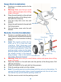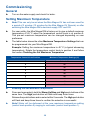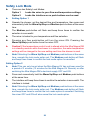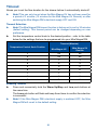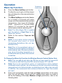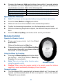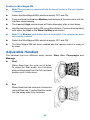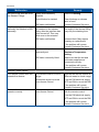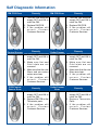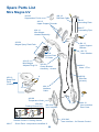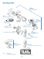
1
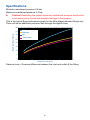
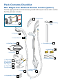
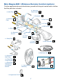
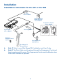
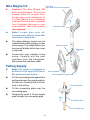
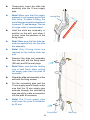
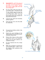
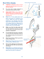
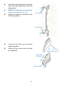
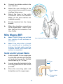
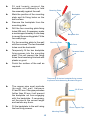
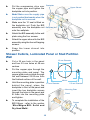
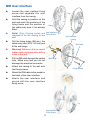
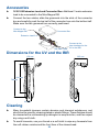
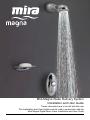
Mira Magna Water Delivery System
Installation and User Guide
These instructions are to be left with the user
This Installation and User Guide must be read in conjunction with the
Mira Magna Digital Mixer Valve Installation and User Guide
1
the nation’s favourite for
PLUMBING & HEATING SUPPLIES
FREE SHIPPING
SECURE PAYMENTS
on all orders over £100 to mainland UK
shop online with confidence
FINANCE AVAILABLE
PRICE MATCH
spread the cost with low interest rates
always get the best deals available
we have
H U G E
R E D U C T I O N S
ON THOUSANDS OF ITEMS
Boilers
Bathroom suites
Radiators
Kitchen sinks & taps
Heating controls
Showers
Pipes & ittings
Wet rooms
Cylinders
Towel warmers
Fires
Bathroom furniture
Renewable energy
& much more
visit our website
plumbnation.co.uk
CALL US ON
0844
800
3460
Cleaning ................................................................................................. 30
Customer Services ................................................................................ 31
Introduction
The Mira Magna Water Delivery System delivers water via the Mira Magna Digital
Mixer (Mira Magna DM) and this guide should be read in conjunction with the Mira
Magna DM Installation and User Guide.
To operate the Mira Magna Water Delivery System, use the interface - refer to the
section ‘Operation’ for more details.
This Installation and User Guide covers the following products:
Mira Magna Universal Variable Water Delivery System (Mira Magna UV)
An adjustable spray handset with four different spray actions (Start, Eco, Champagne
and Massage) is supplied complete with lexible hose, clamp bracket assembly, slide
bar, supports, combined user interface and a wall mounted soap dish.
Mira Magna Built-in Rigid Water Delivery System (Mira Magna BIR)
An adjustable built-in shower head with four different spray actions (Start, Eco,
Champagne and Massage), supplied with wall mounted soap dish and a user
interface. Suitable for connection to concealed pipe work supplies only.
Mira Magna Wireless Remote Control (Option)
The remote control allows the user to start, stop and use the warm up feature on
the water delivery system over a distance of up to 10 metres. The remote control
can be used hand held or when located in its parking socket, it requires no batteries
and is also water resistant (not to be immersed in water).
Design and Patent Registration
Design Registration
000592084
00275789-0003-0004
Patent Application
Int. Pat. App. WO 2006/072799
3
Speciications
Minimum maintained pressure 0.4 bar
Maximum maintained pressure 5.0 bar
Caution! Exceeding the stated maximum maintained pressure could result
in excessive spray forces and possible damage to the product.
This is the typical low performance graph for the Mira Magna shower ittings only.
There will be an additional pressure loss through the digital mixer.
40
Start
Flow Rate (litres/minute)
35
Massage
30
Eco
Champagne
25
20
15
10
5
0
0
0.5
1.0
Pressure Loss (bar)
1.5
2.0
Pressure loss = Pressure difference between the inlet and outlet of the itting.
4
Important Safety Information
Installation must be carried out in accordance with these instructions, and must be
conducted by designated, qualiied and competent personnel.
Warning!
1. Products manufactured by us are safe and risk-free, provided that they
are installed, used and maintained in good working order, in accordance
with our instructions and recommendations.
2. Make sure that any pipework that could become frozen is properly
insulated.
3. DO NOT operate this appliance if it is frozen. Allow the appliance to thaw
before using. The shower unit must not be itted where it may be exposed
to freezing conditions.
4. This product is not suitable for areas with high humidity (e.g. steam rooms).
Please consult your installer.
5. Due to the operational nature of instantaneous water heaters/combination
boiler systems, use of the warm up feature may cause fluctuating
temperatures to be delivered and may take a few seconds to stabilise.
Caution!
1.
2.
3.
4.
Read all of these instructions and retain this guide for later use.
The electrical installation must comply to “BS 7671 - Requirements
for Electrical Installations”, commonly referred to as the IEE Wiring
Regulations - Part 7, or any particular regulations and practices, speciied
by the local electricity supply company.
The plumbing installation must comply with the requirements of UK Water
Regulations/Bye-laws (Scotland), Building Regulations or any particular
regulations and practices, speciied by the local water company or water
undertakers.
Anyone who may have dificulty understanding or operating the controls of
any shower should be attended whilst showering. Particular consideration
should be given to:
• the young
• the elderly
• the inirm
• the disabled
• anyone who suffers from a medical condition that can result in temporary
incapacity (e.g. epilepsy or blackouts)
• anyone inexperienced in the correct operation of the controls.
Standards and Approvals
The Mira Magna complies with all the relevant directives for CE marking.
5
Pack Contents Checklist
Mira Magna UV / Wireless Remote Control (option)
Tick the appropriate boxes to familiarise yourself with the part names and to conirm
that the parts are included.
2 x Top Covers
1 x Concealing
Plate
Wireless Remote Control
1 x Handset
2 x Hose Washers
1 x Concealing Pipe
1 x DM Data Cable
4 x Wall Plugs
1 x Soap Dish
4 x Fixing Screws
1 x Soap Dish
Wall Bracket
2 x Soap Dish
Wall Plugs
2 x Soap Dish
Fixing Screws
1 x Hose
1 x User Interface
Assembly
1 x Suppression Ferrite
6
Mira Magna BIR / Wireless Remote Control (option)
Tick the appropriate boxes to familiarise yourself with the part names and to conirm
that the parts are included.
4 x Mounting
Plate Screws
4 x Wall Plugs
1 x Backplate
1 x Mounting
Plate
1 x Top Cover
1 x ‘O’ Seal
4 x BIR Screws
1 x Olive
2 x Backplate
Screws
1 x Backplate
Nut
4 x Cover
Screws
1 x Soap Dish
1 x Cover
Assembly
1 x BIR Assembly
1 x DM Data Cable
2 x Soap Dish
Wall Plugs
2 x Soap Dish
Fixing Screws
1 x Soap Dish
Wall Bracket
with Bottom
Bracket
1 x User Interface
Assembly
1 x Suppression Ferrite
7
Wireless Remote Control
Installation
Installation Schematic for the UV or the BIR
PSU,
refer to Note 1
3 amp Switched
Fused Spur Box,
refer to Note 1
Suppression Ferrite,
refer to Note 2
Digital Mixer,
refer to Note 1
Mira Magna BIR
Wireless
Remote Control
(option)
Mira Magna BIR
(Wall Mount)
Mira Magna UV
(Shower Mixer)
Note 1! Refer to your Mira Magna DM, Installation and User Guide.
Note 2! The Data Cable must be placed through the Suppression Ferrite and
then looped around the cover. The Suppression Ferrite must be itted as close
to the User Interface as possible.
8
Mira Magna UV
Caution! The Mira Magna DM
and the Mira Magna UV must be
installed within 4 m of each other.
Longer pipe runs (maximum of
7 m) will require a 3 m Extension
Lead and Connector Box (available
from Customer Services or your
local stockist) - refer to the section
‘Accessories’.
Top Cover
(may differ from the one shown)
Interface Cable
Note! Longer pipe runs will
increase water delivery times after
temperature adjustment.
The water delivery system can be
installed with a falling supply or rear
entry supply. The supply option you
choose will dictate which top cover
is required.
Interface Cable
Backplate
Loosen the user interface fixing
screw. Carefully pull the user
interface from the backplate.
Disconnect the interface cable.
Falling Supply
Note! This product is designed to
be itted to a full height fully tiled or
lat waterproof wall surface.
Put the concealing plate against the
ceiling and mark the centre position
for the hole. Carefully drill a 24 mm
hole in the ceiling.
User Interface
User Interface Fixing Screw
Concealing Plate
Fit the concealing plate over the
concealing pipe.
Temporarily insert a 15 mm supply
pipe through the concealing pipe.
Concealing Pipe
15 mm Supply Pipe
9
Temporarily insert the slide bar
assembly onto the 15 mm supply
pipe.
Note! Make sure that the supply
pipework is cut squarely and is free
from burrs. To assist in itting, the
end of the pipe should be chamfered
to prevent ‘O’ seal damage. The use
of a pipe cutter is recommended.
Locking Ring
Hold the slide bar assembly in
position on the wall, and when it
is level, mark the positions of the
ixing holes.
Note! Make sure that the slide bar
ends are pushed fully into the slide
bar assembly.
Note! Only 2 fixing holes are
required on the bottom slide bar
end.
Remove the slide bar assembly
from the wall, drill the ixing holes
(Ø6 mm) and it the wall plugs.
Note! Make sure that the locking
ring is held firmly when pulling
the supply pipe from the push it
connector.
Attach the slide bar assembly to the
wall with the ixing screws.
Cut the concealing pipe and the
15 mm supply pipe to length, make
sure that the 15 mm supply pipe
extends through the concealing
pipe enough to make a connection
into the push it connector.
Note! The 15 mm supply pipe
must enter the push it connector
by 30 mm.
Fixing Screw
10
Wall Plugs
Important! Do not it the pipe at
this stage. Once the pipe assembly
has been cut to length, remove
the 15 mm supply pipe from the
concealing pipe.
Put the data cable through the
concealing pipe. Carefully it the
15 mm supply pipe through the
concealing pipe. Make sure that
you fit the top cover over the
concealing pipe then connect to
the push it connector.
Concealing Pipe
Top Cover
15 mm Supply
Pipe from Digital
Mixer
Data Cable
Connect the data and interface
cables together.
Push the top cover onto the slide
bar assembly.
Push Fit
Connector
Interface Cable
Connect the interface cable to the
user interface.
Attach the user interface to the
rear case and secure with the user
interface ixing screw.
Attach the hose to the outlet
connection and to the handset.
Make sure the hose washers are
installed correctly.
Put the handset into the clamp
bracket.
Make the plumbing connections
to the Digital Mixer - refer to your
Mira Magna DM Installation and
User Guide.
User Interface Fixing Screw
11
Rear Entry Supply
Caution! Pipework must not be
soldered while attached to the water
delivery system.
Supply pipework from the DM
22 mm max. Hole Size
13.5 mm
For rear entry supply pipework a
soldered elbow must be used.
65 mm
max.
Important! Make sure that the
dimensions do not exceed the ones
shown, otherwise you will not be able
to it the unit.
Note! The 15 mm supply pipe must
enter the push fit connector by
30 mm. Make sure that the supply
pipework is cut squarely, free from
burrs and to assist in itting. The end
of the pipe should be chamfered to
prevent ‘O’ seal damage. The use of
a pipe cutter is recommended.
Make sure that the data cable and
inished pipework protrude through
the wall before the inal inished wall
surface is completed.
15 mm Supply Pipe
30 mm min.
Soldered
Elbow
30 mm Pipe
Insertion
Put the slide bar assembly in position
on the wall and temporarily push it
the soldered elbow into the push it
connector.
Mark the positions of the top and the
bottom ixing holes.
Note! Only 2 ixing holes are required
on the bottom slide bar end.
Remove the slide bar assembly from
the wall and drill (Ø6 mm) and it the
wall plugs.
Note! Make sure that the locking ring
is held irmly when pulling the supply
pipe from the push it connector.
12
Locking Ring
Push-it in-line
Connector
Hold the supply pipe irmly and push
the slide bar assembly onto the
supply pipe.
Note! The supply pipe must enter the
push it connector by 30 mm.
Fixing Screws
Attach the slide bar assembly with
the ixing screws.
Fixing Screws
Connect the data and interface
cables together.
Attach the top cover onto the slide
bar assembly.
Top Cover
Supply Pipe from DM
Data Cable
from DM
Interface Cable
13
Connect the interface cable to the
user interface.
Attach the user interface to the
rear case and secure with the user
interface ixing screw.
Attach the hose to the outlet
connection and to the handset.
Make sure the hose washers are
installed correctly.
Put the handset into the clamp
bracket.
Make the plumbing connections
to the Digital Mixer - refer to your
Mira Magna DM Installation and
User Guide.
Mira Magna BIR
Note! The BIR ittings can be itted
to a variety of wall surfaces or
structures.
User Interface Fixing Screw
Note! If the data cable is chased
into a solid wall or installed in
ducting, the data cable must be
installed before the inished wall
surface is completed.
Solid and Dry-lined Walls
Install recessed 15 mm copper pipe
from the DM and make sure the pipe
will protrude through the inished
wall surface by 23 - 25 mm.
23-25 mm
Loosely screw the backplate to the
mounting plate with the two screws
provided.
Place the mounting plate and
backplate over the copper pipe.
15 mm Copper
Pipe
Finished Wall
Surface
14
Fit and loosely connect the
backplate nut suficiently to hold
the assembly against the wall.
Mounting Plate
Mark the position of the mounting
plate and its ixing holes on the
wall surface.
Backplate
Remove the backplate from the
mounting plate.
Drill the four mounting plate ixing
holes (Ø6 mm). If necessary, make
a recess approximately 6 mm deep
to accept the mounting plate. Fit the
four wall plugs.
Fix the mounting plate to the wall
with four screws. The two threaded
holes must be horizontal.
Backplate Nut
Mounting Plate
6.0 mm
Temporarily it the two backplate
fixing screws into the mounting
plate. This will prevent the ixing
holes from becoming blocked with
plaster or grout.
Threaded Holes
Finish the surface of the wall as
required.
Temporarily it the two backplate ixing screws
to prevent holes becoming blocked with grout
The copper pipe must protrude
through the wall between
23 and 25 mm. If the pipe protrudes
further than 25 mm it will prevent
the backplate nut from engaging
with the backplate. If necessary,
cut the pipe to the correct length
and remove any burrs.
23-25 mm
Fit the backplate to the wall using
the two ixing screws.
15 mm Copper Pipe
Mounting Plate
15
Put the compression olive over
the copper pipe and tighten the
backplate nut into position.
Backplate
Upper Shroud
Note! Make sure the supply pipe
is not pushed backwards when the
backplate nut is secured.
Make sure the ‘O’ seal is itted on
the backplate nut. Push the BIR
assembly over the backplate nut
onto the wallplate.
Backplate Nut
Attach the BIR assembly to the wall
plate using the four screws.
Attach the upper shroud to the BIR
assembly using the four self-tapping
screws.
Lower Shroud
Snap the lower shroud into
position.
Shower Cubicle, Laminated Panel or Stud Partition
Wall
Cut a 25 mm hole in the panel
and two 5.5 mm holes at 48 mm
centres.
25 mm Diameter
Put the copper pipe through the
mounting plate and panel. The
copper pipe must protrude through
the wall between 23-25 mm from
the inished surface of the wall.
Hold the mounting plate in position
behind the panel, place the
backplate in front of the panel and
insert the two backplate screws
through the holes in the panel and
it them into the mounting plate
and tighten.
To complete the installation of the
BIR ittings - refer to the section
‘Mira Magna BIR: Solid and
Dry-lined Walls’.
16
48 mm
5.5 mm Diameter
5.5 mm Diameter
Mounting Plate
Panel
Screws
BIR User Interface
Loosen the user interface fixing
screw and separate the user
interface from the casing.
Hold the casing in position on the
wall and mark the positions of the
fixing holes and the position of
the cable entry hole, if not already
itted.
Note! Only 2 fixing holes are
required to fix the casing to the
wall.
Casing
User Interface
Fixing Screw
User Interface
Casing
Drill the ixing holes (Ø6 mm), the
cable entry hole (Ø15 - 20 mm) and
it the wall plugs.
DM Cable
Warning! Make sure that you avoid
hidden cable and pipes when drilling
holes in the wall.
Put the DM cable through the central
hole. Make sure that you do not
damage the electrical connector.
Wall Plugs
Attach the casing to the wall with
the ixing screws.
Fixing Screws
Attach the DM cable to the socket in
the back of the user interface.
Attach the user interface and
secure with the user interface
ixing screw.
User Interface
Fixing Screw
17
Soap Dish Installation
Decide on a suitable position for the
soap dish.
Warning! Make sure that you avoid
hidden cables and pipes when drilling
holes in the wall.
Place the wall bracket on the wall and
mark the position of the ixing holes.
Drill (Ø6 mm) and plug.
Clip the soap dish onto the wall
bracket.
Wall Bracket
Attach the wall bracket to the wall with
the ixing screws.
Clip the bottom cover onto the wall
bracket.
Remote Control Installation
Soap Dish
Bottom Cover
Decide on a suitable position for the
Retainer
remote control outside the showering
Fixing Screw
area. Refer to the illustration for ixing
Parking Socket
details.
Note! The remote control can be
sited up to 10 m from the user
interface. Wall thickness and
construction will affect this distance,
so before permanently fixing the
parking socket, make sure the water
Wall Plug
delivery system can be operated by
the remote control in the desired
Retainer Clip
ixing location - refer to the section
Cut-out
Remote Control
‘Operation, Remote Control’.
Warning! Make sure that you avoid hidden cables and pipes when drilling
holes in the wall.
Place the retainer on the wall and mark the position of the ixing holes. Drill
(Ø6 mm) and plug.
Attach the retainer to the wall with the ixing screws.
Slide the parking socket onto the retainer.
Note! The parking socket must be placed with the cut-out on the bottom. To
remove the parking socket, place a small screwdriver into the cut-out, lever
the retainer clip up and slide the parking socket off.
Clip the remote control into the parking socket.
18
Commissioning
General
Turn on the water supply and check for leaks.
Setting Maximum Temperature
Note! This can only be set when the Mira Magna UV has not been used for
a period of 3 minutes (10 minutes for the Mira Magna UV Remote) or after
switching the Mira Magna DM’s electrical supply OFF and ON.
For user safety, the Mira Magna DM is factory set to give a default maximum
temperature of 45 °C when the temperature control knob is at position 9.
This pre-set maximum temperature can be changed depending on user
preference.
The table below shows the other Maximum Temperature Settings that can
be programmed into your Mira Magna DM.
Example: Setting the maximum temperature to 40 °C (a typical showering
temperature). Rotate the temperature control knob to position 5 and follow
the section ‘Enabling the Set Maximum Temperature’.
Temperature Control Knob Position
Maximum Temperature Settings (oC)
1
Default 45
2
45
3
36
4
38
5
40
6
42
7
44
8
46
9
48
Enabling the Set Maximum Temperature
Press and momentarily hold the Warm Up/Stop and High push-buttons at the
same time. The High push-button will lash and beep three times.
Release the push-buttons and re-select within 2 seconds. The High push-button
will lash and beep three times to conirm the selection is successful.
Note! Water will be delivered at the new maximum temperature setting
(control knob position 9) ranging to cold water (control knob position 1).
19
Safety Lock Mode
There are two Safety Lock Modes:
Option 1
Locks the mixer to your low and temperature settings.
Option 2
Locks the interface so no push-buttons can be used.
Setting Option 1
Operate the shower, set the desired low and temperature, then press and
momentarily hold the Warm Up/Stop and Medium push-buttons at the same
time.
The Medium push-button will lash and beep three times to conirm the
selection is successful.
The mixer is locked to your temperature and low selection.
Pressing any flow push-button will turn the mixer ON. Pressing the
Warm Up/Stop push-button turns the mixer OFF.
Caution! If the temperature control knob is altered while the Mira Magna DM
is in standby mode or while the shower is in operation, the water temperature
settings will be changed to the new setting next time the shower is used.
Note! Selecting the Warm Up/Stop and Medium push-buttons at the same
time, cancels the lock mode option set. The Medium push-button will lash
and beep three times to conirm the lock mode option is cancelled.
Setting Option 2
Note! This can only be set when the Mira Magna UV has not been used for
a period of 3 minutes (10 minutes for the Mira Magna UV Remote) or after
switching the Mira Magna DM’s electrical supply OFF and ON.
Press and momentarily hold the Warm Up/Stop and Medium push-buttons
at the same time.
The interface will beep three times to conirm the selection is successful. The
interface is locked.
Note! Selecting the Warm Up/Stop and Medium push-buttons at the same
time, cancels the lock mode option set. The Medium push-button will lash
and beep three times to conirm the lock mode option is cancelled. Switching
the mixer OFF and ON will also cancel the lock mode option.
20
Timeout
Allows you to set the low duration for the shower before it automatically shuts off.
Note! This can only be set when the Mira Magna UV has not been used for
a period of 3 minutes (10 minutes for the Mira Magna UV Remote) or after
switching the Mira Magna DM’s electrical supply OFF and ON.
Timeout Selection
Note! The Mira Magna DM timeout function is factory set to run for 30 minutes
(default setting). This timeout period can be changed depending on user
preference.
Set the temperature control knob to the desired position - refer to the table
below for the settings that can be programmed into your Mira Magna DM.
Timeout (Minutes)
Temperature Control Knob Position
Mira Magna UV
Mira Magna UV
Remote
1
50
30
2
50
30
3
3
3
4
4
4
5
5
5
6
6
6
7
7
7
8
8
8
9
9
9
Enabling Timeout
Press and momentarily hold the Warm Up/Stop and Low push-buttons at
the same time.
The Low push-button will lash and beep three times to conirm the selection
is successful.
Note! If the Mira Magna DM’s electrical supply is switched OFF, the Mira
Magna DM will revert to the default setting.
21
Operation
Temperature
Control Knob
Warm Up Function
Press the Warm Up/Stop push-button.
To allow the user to get out of the shower
the unit delays for a few seconds before
turning on.
The Warm Up/Stop push-button lashes
for a number of seconds until water
comes out of the handset at the selected
temperature, then turns off (Standby
mode - maximum of 2 minute delay
feature (10 minutes for the remote
control option) before switching off).
Note! The Mira Magna DM is supplied
with the default of High Flow for the
Warm Up Function.
Refer to the section ‘Operate the
Shower’.
Note! A long delay before entering
the shower may result in initial
temperature luctuations (the unit has
switched OFF).
Note! Due to the operational nature of
instantaneous water heaters/combination
boiler systems, use of the warm up feature
may cause luctuating temperatures to
be delivered and may take a few seconds
to stabilise.
To Change the Warm Up Function for Wireless Remote Control Option Only
Note! This can only be set when the DM has not been used for a period of
10 minutes or after switching the DM’s electrical supply OFF and ON.
Note! Due to the operational nature of instantaneous water heaters/
combination boiler systems, use of the warm up function may cause luctuating
temperatures to be delivered when re-started and may take a few seconds
to stabilise. We recommend that continuous Medium or High Flow modes
are used.
Press and momentarily hold the Low and High push-buttons at the same
time, the unit will beep 3 times and will indicate which warm up mode is
set by the lashing of the Low, Medium or High push-button, refer to the
following table.
22
Pressing the Low and High push-buttons twice within 2 seconds selects
the next warm up mode. Repeat the procedure until you have selected your
required warm up mode. Refer to the following table:
Low push-button lashing
The unit warms up and switches to standby mode (no low)
Medium push-button lashing
The unit warms up and switches to medium low
High push-button lashing
The unit warms up and switches to high low
Operate the Shower
Note! The shower can be operated without using the Warm Up function.
Press the Low, Medium or High push-button.
Water will come out of the handset at the selected temperature.
To alter the showering temperature, turn the temperature control knob.
While the showering temperature adjusts, the selected low push-button will
lash.
Press the Warm Up/Stop push-button at the end of your shower.
Remote Control
Operate the Remote Control
Press and momentarily hold the Start
push-button.
Start
Water will be delivered on High low.
Press and momentarily hold the Warm Up/Stop
push-button at the end of your shower either on
the remote or on the interface.
Warm Up
Using the Warm Up Function
Pressing the Warm Up/Stop push-button starts
this function - refer to the section ‘Warm Up
Function’ for more details.
Note! There is no time delay function when
using the remote control.
Stop
Remote Control
Caution! When using the remote control in its socket, press the buttons
carefully to avoid accidentally dislodging it from its socket.
Timeout Function
The Mira Magna DM is supplied with a timeout default set. The shower will
operate and automatically shut off after a set period - refer to the section
‘Timeout’ for more details.
23
Enable the Mira Magna DM
Note! This procedure is required should the remote control or the user interface
is replaced.
Switch the Mira Magna DM’s electrical supply OFF and ON.
Press and hold the Low and Medium push-buttons at the same time until the
interface stops beeping.
The Low and High push-buttons will lash alternately after a short delay.
Hold the remote control within 200 mm of the interface. Press and momentarily
hold either the Start or the Warm Up/Stop push-button.
Note! The Medium push-button will be illuminated if the remote has been
successfully enabled.
Switch the Mira Magna DM’s electrical supply OFF and ON.
The Mira Magna DM has been enabled and the remote control is ready to
be used.
Adjustable Handset
The handset has four different spray modes, Start, Eco, Champagne and
Massage.
Start
Water lows from the outer set of holes.
To select the Start mode, turn the spray
plate anticlockwise from the full clockwise
position until it clicks once.
Eco
Water lows from the outer set of holes at a
reduced low rate. To select the Eco mode,
turn the spray plate fully clockwise.
24
Champagne
Water lows from the middle set of holes. To
select the Champagne mode, turn the spray
plate anticlockwise from the full clockwise
position until it clicks twice.
Massage
Water lows from the inner set of holes. To
select the Massage mode, turn the spray
plate anticlockwise from the full clockwise
position until it clicks three times.
Fault Diagnosis
The trouble shooting information below gives details on what you can do as a user
should you encounter dificulties whilst operating the shower.
If there is a problem with the interface some of the push-buttons may lash very fast,
refer to the section ‘Self Diagnostic Information’.
Malfunction
Push-buttons are lashing
on the interface and / or the
shower will not operate.
Cause
Remedy
Water supply isolated.
Check water supply.
Damaged or broken cable
connection.
Check cable connections.
Electrical supply isolated or
fuse blown.
Check electrical supply.
DM Valve breakdown.
Isolate the electrical supply and
turn back on after 30 seconds.
If the problem persists,
note the sequence of the
lashing push-buttons and
with the information from Self
Diagnostic Information,
contact Customer Services.
Continued
25
Continued
Malfunction
No low or low low rate from
the Shower Fittings.
Drip from spray plate
assembly on handset or BIR
assembly.
Cause
Remedy
Spray plate assembly
blocked.
Refer to Cleaning.
Hose blocked or twisted.
Clear blockage or release
twist in hose.
DM Valve malfunction.
A small amount of water may
be retained in the shower
itting after the interface has
been turned off. This may
drain over a few minutes.
Contact Customer Services.
This is quite normal. Changing
the angle of the shower itting
may vary the draining time.
DM Valve malfunction.
Solenoid fault. May require
cleaning or replacement.
Incorrect shower temperature. Maximum temperature
incorrectly set.
DM Valve incorrectly itted.
If the problem still occurs,
Contact Customer Services.
Refer to Commissioning:
Maximum Temperature
Setting.
Make sure that the hot and
cold water supplies are
connected correctly.
If the problem still occurs,
Contact Customer Services.
Remote Control Option
The remote control does not
operate the shower.
The interface does not
operate correctly.
The remote control is out of
range.
Operate the remote control in
different areas to check range.
Incomplete signal received
from remote control.
Turn the DM electrical supply
OFF and ON to re-set the DM.
Incomplete signal received
from remote control.
If the problem still occurs,
Contact Customer Services.
Switch the shower OFF/ON
with the remote control.
Turn the DM electrical supply
OFF and ON to re-set the DM.
If the problem still occurs,
Contact Customer Services.
26
Self Diagnostic Information
DM PCB Error
Remedy
DM PCB Error
1. Turn the DM electrical
supply OFF and ON to
reset the DM.
2. Replace DM PCB.
3. If the problem still
occurs, Contact
Customer Services.
1. Turn the DM electrical
supply OFF and ON to
reset the DM.
2. Replace DM PCB.
3. If the problem still
occurs, Contact
Customer Services.
Over Temp at
Control Sensor
Over Temp at
Outlet Sensor
Remedy
1. Turn the DM electrical
supply OFF and ON to
reset the DM.
2. Make sure Hot and
Cold inlets are not
reversed.
3. Make sure that the inlet
filters and non-return
valves are clean.
4. If the problem still
occurs, Contact
Customer Services.
PCB/Control
Sensor Error
1. Turn the DM electrical
supply OFF and ON to
reset the DM.
2. Replace DM PCB or the
Thermistor pack.
3. If the problem still
occurs, Contact
Customer Services.
27
Remedy
1. Turn the DM electrical
supply OFF and ON to
reset the DM.
2. Make sure Hot and
Cold inlets are not
reversed.
3. Make sure that the inlet
ilters are clean.
4. If the problem still
occurs, Contact
Customer Services.
Outlet Sensor
Error
Remedy
Remedy
Remedy
1. Turn the DM electrical
supply OFF and ON to
reset the DM.
2. Replace Thermistor
Pack.
3. If the problem still
occurs, Contact
Customer Services.
Spare Parts List
Mira Magna UV
464.18
DM Data Cable
464.29
Suppression Ferrite
464.06
Concealing Plate
464.13
Upper Support Shrouds
464.07
Concealing Pipe
464.14
Mira Magna
Handset Assembly
464.24
Magna Spray Plate Pack
A
A
464.12
Upper Support
Bracket
623.73
Hose Washer
450.08
Service Pack
‘O’ Seals
464.15
Mira Magna
Adjuster Ring UV
450.24
Clamp Bracket
Assembly - chrome
464.11
Hose 1.75 m
450.28
Slide Bar
(chrome)
A
452.10
Soap Dish
Pack
(chrome)
464.16
Interface
Cable
A
A
464.08
Temperature Knob
1636.041
Parking Socket Only
A
464.09
User Interface
1636.040
Remote Control + Parking Socket
464.17
464.10
User Interface
Rear Case
1636.042
User Interface - for Remote Control
Screw Pack - components identiied ‘A’
28
Mira Magna BIR
464.20
Mira Magna
BIR Power Assembly
450.43
BIR Mounting Pack
464.24
Mira Magna
Spray Plate
Pack
464.19
DM Data Cable
A
450.08
Service Pack ‘O’ Seals
464.29
Suppression Ferrite
464.22
User Interface Wall Mount Case
464.21
Mira Magna
Adjuster Ring BIR
A
464.08
Temperature Knob
464.23
User Interface
A
A
452.10
Soap Dish Pack
(chrome)
1636.043
User Interface - for Remote Control
1636.041
Parking Socket Only
464.17
Screw Pack
components identiied ‘A’
1636.040
Remote Control + Parking Socket
29
Accessories
1618.106 Extension Lead and Connector Box: Additional 3 metre extension
lead to be connected to the Mira Magna DM.
Connect the two cables, slide the grommets into the slots of the connector
box and carefully push the top half of the connector box onto the bottom half.
Make sure the two grommets are correctly positioned.
Connect to the
Mira Magna DM
Connector Box
Extension Lead 3 m
DM Data Cable
Connect to the
User Interface for the
UV or the BIR
Dimensions for the UV and the BIR
158 mm
225 mm
641 mm
792 mm
86 mm
70 mm
Cleaning
Many household cleaners contain abrasive and chemical substances, and
should not be used for cleaning plated or plastic ittings. These inishes should
be cleaned with a mild washing up detergent or soap solution, and then wiped
dry using a soft cloth.
To avoid limescale, use your thumb or a soft cloth to wipe any limescale from
the soft rubber nozzles and the front face of the showerhead.
30
Customer Services
Guarantee of Quality
Spare Parts
Mira Showers guarantee your product against any defect
in materials or workmanship for the period shown in the
Guarantee Registration Document included with your
shower.
Alternatively, to conirm the applicable guarantee period
please contact Customer Services.
To validate the guarantee, please return your completed
registration card.
Within the guarantee period we will resolve defects, free
of charge, by repairing or replacing parts or modules as
we may choose.
To be free of charge, service work must only be undertaken
by Mira Showers or our Approved Agents in Northern Ireland
and the Republic of Ireland.
Service under this guarantee does not affect the expiry date.
The guarantee on any exchanged parts or product, ends
when the normal product guarantee period expires.
We maintain an extensive stock of spares, and aim to have
functional parts available for ten years from the date of inal
manufacture of the product.
Spares can be purchased from approved stockists or
merchants (locations on request) or direct from Customer
Services.
Spares direct will normally be despatched within two working
days. Payment can be made by Visa or Mastercard at the
time of ordering. Should payment by cheque be preferred
a pro-forma invoice will be sent.
Note! In the interests of safety, spares requiring exposure
to mains voltages can only be sent to competent persons.
Service
Our Service Force is available to provide a quality service
at a reasonable cost. You will have the assurance of a
Mira trained Engineer/Agent, genuine Mira spares and a
12 month guarantee on the repair.
Not covered by this guarantee
Payment should be made directly to the Service Engineer/
Damage or defects arising from incorrect installation, Agent, using Visa, MasterCard or a cheque supported by
improper use or lack of maintenance, including build-up a banker’s card.
of limescale.
Damage or defects if the product is taken apart, repaired To contact us
or modiied by any person not authorised by Mira Showers England, Scotland & Wales
Mira Showers Customer Services
or our Approved Agents.
This guarantee is in addition to your statutory and other Telephone: 0870 241 0888
Mon. to Fri. 8:00 am to 5:30 pm
legal rights.
8:30 am to 3:30 pm Saturday
Before using your shower
E-mail:
[email protected]
Please take the time to read and understand the operating Fax:
01242 282595
and safety instructions detailed in this manual.
By Post:
Cromwell Road, Cheltenham,
Gloucestershire, GL52 5EP
What to do if something goes wrong
If when you irst use your shower and it doesn’t function
correctly, first contact your installer to check that the
installation and commissioning are satisfactory and in
accordance with the instructions in this manual.
Should this not resolve the dificulty, simply contact our
Customer Services who will give every assistance, and if
necessary arrange for our Service Engineer to visit.
If later the performance of your shower declines, consult
this manual to see whether simple home maintenance
is required. Please call our Customer Services to talk
the dificulty through, request service under guarantee
if applicable, or take advantage of our comprehensive
After-Sales Service.
As part of our quality and training programme calls may be
recorded or monitored.
Our Customer Services Team is comprehensively trained to
provide every assistance you may need: help and advice,
spare parts or a service visit.
Northern Ireland
Wm H Leech & Son Ltd
Telephone: 028 9044 9257
Mon. to Fri. 9:00 am - 5:00 pm
E-mail:
[email protected]
Fax:
028 9044 9234
Post:
Maryland Industrial Estate
Ballygowan Road, Moneyreagh,
Co Down, BT23 6BL
Republic of Ireland
Modern Plant Ltd. (Dublin)
Telephone: 01 459 1344
Mon. to Fri. 9:00 am - 5:00 pm
E-mail:
[email protected]
Fax:
01 459 2329
Post:
Otter House, Naas Road,
Clondalkin, Dublin 22
Modern Plant Ltd. (Cork)
Telephone: 021 496 8755
Mon. to Fri. 9:00 am - 5:00 pm
E-mail:
[email protected]
Fax:
021 496 8607
Post:
Tramore Road, Cork
31
Mira Showers
Kohler Mira Ltd.
Cromwell Road
Cheltenham
GL52 5EP
1059237-W2-A
Mira is a registered trade mark of
Kohler Mira Limited.
The company reserves the right to alter
product speciications without notice.
www.mirashowers.com
32
© Kohler Mira Limited, October 2006